Graco G3 Instructions Manual
Standard automatic lubrication pump
Hide thumbs
Also See for G3:
- Instructions manual (88 pages) ,
- Instructions (4 pages) ,
- Instruction manual (77 pages)
Table of Contents
Advertisement
Quick Links
Instructions
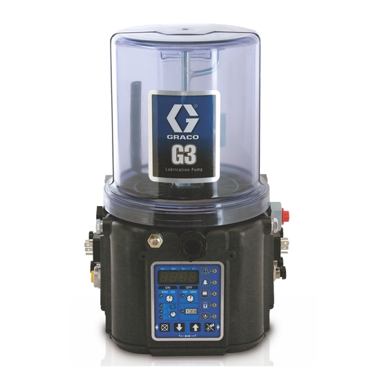
G3 Standard Automatic
Lubrication Pump
For dispensing of NLGI Grades #000 to #2 greases and oils with at least 40cSt. For
professional use only.
Not approved for use in explosive atmospheres or hazardous (classified) locations.
Part Nos., page 3
5100 psi (35.1 MPa, 351.6 bar) Pump Output Pressure
5000 psi (34.3 MPa, 344.8 bar) Fill Inlet Pressure
Important Safety Instructions
Read all warnings and instructions in this
manual before using the equipment.
Save these instructions.
Conforms to ANSI/UL 73
Certified to CAN/CSA
Std. 22.2 No 68-09
3132066
24V and 110-240VAC Pumps ONLY
332291P
EN
Advertisement
Table of Contents

Related Manuals for Graco G3


Summary of Contents for Graco G3
- Page 1 Instructions G3 Standard Automatic Lubrication Pump 332291P For dispensing of NLGI Grades #000 to #2 greases and oils with at least 40cSt. For professional use only. Not approved for use in explosive atmospheres or hazardous (classified) locations. Part Nos., page 3 5100 psi (35.1 MPa, 351.6 bar) Pump Output Pressure...
-
Page 2: Table Of Contents
California Proposition 65 ....41 Graco Standard Warranty ....42... -
Page 3: Part / Model Numbers
Part / Model Numbers The Part Number is a six-digit unique number that is only used to order the G3 Pump. Directly related to this six digit Part Num- ber is the configured Graco Model Number. This configured number identifies the distinct features of a specific G3 Pump. To help you understand each component that makes up the Model Number see Understanding the Model Number, page 5. -
Page 4: Liter Models
8 Liter Models 12 Liter Models Part Part Model Number Model Number Numbers Numbers 96G039 G3-G-12NC-8L0000-00C00000 96G057 G3-G-ACNC-120A00-LD000000 96G041 G3-G-24NC-8L0000-00C00000 96G171 G3-G-24NC-120000-00C00000 96G043 G3-G-ACNC-8L0000-0D000000 96G199 G3-G-24NC-120A00-L0C00000 96G045 G3-G-12NC-8L0A00-L0C00000 96G240 G3-G-24NC-120A00-0D00L000 96G049 G3-G-24NC-8L0A00-L0C00000 16 Liter Models 96G052 G3-A-24NC-8L0A00-L0C00000 96G056 G3-G-ACNC-8L0A00-LD000000 96G061... -
Page 5: Understanding The Model Number
Use the Code Sample provided below to identify each component’s location in the Model Number. The options for each component that make up the code are provided on the lists below. NOTE: Other pump configurations are available that are not documented in this manual. Contact Graco Customer Service or your local Graco distributor for assistance. -
Page 6: Warnings
Warnings Warnings The following warnings are for the setup, use, grounding, maintenance, and repair of this equipment. The exclamation point symbol alerts you to a general warning and the hazard symbols refer to procedure-specific risks. When these symbols appear in the body of this manual or on warning labels, refer back to these Warnings. Product-specific hazard symbols and warnings not covered in this section may appear throughout the body of this manual where applicable. - Page 7 Warnings WARNING SKIN INJECTION HAZARD High-pressure fluid from dispensing device, hose leaks, or ruptured components will pierce skin. This may look like just a cut, but it is a serious injury that can result in amputation. Get immediate surgical treatment. •...
- Page 8 Warnings WARNING MOVING PARTS HAZARD Moving parts can pinch, cut or amputate fingers and other body parts. • Keep clear of moving parts. • Do not operate equipment with protective guards or covers removed. • Equipment can start without warning. Before checking, moving, or servicing equipment, follow the Pressure Relief Procedure and disconnect all power sources.
-
Page 9: Installation
Pressure Relief Valve (Not included (not shown) / required Vent Hole for Follower Plate (grease models only / not for each outlet - Available from Graco. See Parts, page available on all grease models) 35.) Fill cap (oil models only) -
Page 10: Typical Installation
- Proximity Switch (Divider Installations) let - user supplied. See Parts, page 35) - Pressure switch (Injector Installations) Supply Hose (user supplied) Vent valve (Not included / available from Graco. See Series progressive divider valves (Divider Installations) Parts, page 36.) - Injectors (Injector Installations) -
Page 11: Typical Installation - With Remote Fill Manifold
Installation Typical Installation - With Remote Fill Manifold The installation shown is only a guide for selecting and installing system components. Contact your Graco distributor for assistance in planning a system to suit your needs. Key: G3 Pump Auto-Fill Shut Off Valve... -
Page 12: Optional Installation - Without Remote Fill Manifold
Installation Optional Installation - Without Remote Fill Manifold The installation shown is only a guide for selecting and installing system components. Contact your Graco distribu- tor for assistance in planning a system to suit your needs. NOTE: The remote filling station pump stalls (dead-heads) when the reservoir is full. If the pump does not stall (dead-head) there is a leak in the system. -
Page 13: Choose An Installation Location
Always mount the G3 oil models upright. all state and local codes and regulations. • Mount top fill G3 pump models so that there is If the product is permanently connected, it must be: a a minimum clearance of four inches (4.0 in.) (10.2 cm) above the reservoir to allow for lid... - Page 14 To avoid equipment damage: Diagram Page Symbol • Never operate G3 Pump DC models without a Power DIN AC fuse installed. • A fuse of the correct voltage must be installed in line with the power entry to the system.
- Page 15 Installation Power DIN DC - 15 foot Power CPC DC - 15 foot Pin and Related Wire Color (F . 8) Pin and Related Wire Color (F . 9) Pin Name Color Pin Name Color -VDC Black Not Used Not Used +VDC White -VDC...
- Page 16 Installation Power CPC DC - With Low Low Level Outputs Level See Low Level Output Option, page 27 for functional description. See Technical Specifications, page 40 for ratings. Pin and Related Wire Color (F . 10) Pins (F . 11) Pin Name Color Pin Name...
- Page 17 Installation Part No. 124300: Field Wireable Pin Out (M12) Wire Colors (F . 14) Item No. Color Brown White Blue Black . 12 Part No. 124333: Cable Pin Out (M12) Wire Colors (F . 13) Item No. Color Brown White Blue Black .
- Page 18 Installation Part No. 124594: 4 Pin Eurofast Male Field Wireable Connector (F . 15) . 15 Part No. 124595: 5 Pin Eurofast Male Field Wireable Connector (F . 16) . 16 332291P...
-
Page 19: Setup
G3 pump from damage. • Only use a pressure relief valve that is rated for no more than the working pressure of any com- ponent installed in the system. -
Page 20: Set Pump Outlet Volume
• Do not overfill the reservoir. • Do not operate the G3 pump without a reservoir . 18 attached. 3. If needed, remove or insert spacers to achieve the required pump output volume. A tool may be needed to facilitate removal. - Page 21 Setup Models Without a Follower Plate Models with Top Fill 1. Connect the fill hose to the Zerk Inlet Fill Fitting . 19). MOVING PARTS HAZARD Moving parts can pinch, cut or amputate fingers and other body parts. • Keep clear of moving parts. •...
- Page 22 Setup 3. Fill the reservoir with grease until the seal of the follower plate breaches the vent hole and the NOTICE majority of air is expelled from the reservoir. Any debris or dirt accidentally introduced into the res- ervoir should be removed immediately. Do not allow NOTE: The vent port, located in rear of reservoir, the pump to operate until any debris or dirt are should not be used as an overfill port/indicator.
-
Page 23: Auto-Fill Shut Off
Setup Auto-Fill Shut Off The Auto-Fill Shut Off is used for refilling the G3 reservoir in an automatic lubrication system. As fluid is added to the reservoir, the plate valve is pushed up to COMPONENT RUPTURE HAZARD the top of the reservoir, pushing the valve pin and The maximum working pressure of each component closing the inlet fluid path. - Page 24 2. Connect Supply Hose (J) at Quick Connect (V). 3. Turn on remote filling station pump (F) and fill the G3 reservoir (D) until the indicator pin on the Auto-Fill Valve pushes up as shown in F . 24. The pressure in the refill pump (F) builds and the pump stalls.
- Page 25 Setup Remote Filling Station Pressure Relief The reference letters used in the following instructions refer to the F . 6, page 12. The following Pressure Relief Procedure is only used with the Auto-Fill Shut Off Valve to relieve remote filling station and lubricant supply line pressure.
-
Page 26: Fill The Oil Unit
• Do not overfill (F . 26). • Do not operate G3 without reservoir attached. • Only use oils with viscosity at least 40 cSt. . 27 2. Only run pump until air-free lubricant is dispensed out of element fitting (F . -
Page 27: Pump Operation
Pump Operation Pump Operation Low Level Output Option The G3 Pump can be controlled using an external, user supplied, power source and controller. Some G3 pumps without controllers include a Low Level Output Option. It can be configured with an M12 Refer to System Configuration and Wiring, page 13 connector in code location “h”... - Page 28 Pump Operation Oil Pumps To ensure that a low level condition has been met, the low level trigger must be detected for 10 continuous When the oil level has reached a low warning level, seconds. PINS 3 and 4 close, sending the signal to the controller that the fluid has reached a low level.
-
Page 29: Recycling And Disposal
Recycling and Disposal Recycling and Disposal End of Product Life At the end of the product’s useful life, dismantle and recycle it in a responsible manner. • Perform the Pressure Relief Procedure, page 19. • Drain and dispose of fluids according to applicable regulations. -
Page 30: Troubleshooting
Ensure vent hole is not plugged. Lubricant leaks past seal located on filling the bottom of the reservoir If problem persists, contact Graco Customer Service or your local Graco distributor for assistance. Unit not pumping during ON cycle, Failed motor Replace unit. -
Page 31: Maintenance
Keep all fittings clean using a clean dry cloth. Dirt and/or debris can damage pump and/or lubrication system. Daily G3 Pump Unit and Reservoir Keep pump unit and reservoir clean using a clean dry cloth. Monthly External Wiring Harness Verify external harnesses are secure. -
Page 32: Parts - 2 Liter Models
Parts - 2 Liter Models Parts - 2 Liter Models Follower Plate Models Low Level Grease Models Low Level Oil Models Torque to 4 in. lbs (0.45 N.m) Torque to 30 in. lbs (3.4 N.m) Torque to 50 in. lbs (5.6 N.m) 332291P... -
Page 33: Parts - 4 Liter And Larger Models
Parts - 4 Liter and Larger Models Parts - 4 Liter and Larger Models Torque to 4 in. lbs (0.45 N.m) 4L Top Fill Reservoir Torque to 30 in. lbs (3.4 N.m) Follower Plate Models Torque to 50 in. lbs (5.6 N.m) Auto-Fill Shut Off Models Low Level Grease Models Low Level Oil Models... -
Page 34: Parts
COVER, bottom, with seal 40b 16G020 RESERVOIR, 4 Liter, oil, included in kit 571182 115477 SCREW, mach, torx pan hd 17F484 RESERVOIR, 4 Liter, G3 AFSO 127079 RECT-RING, included in kit 278139 SEAL, follower plate, 2 Liter models 571042, 571069, 571179... - Page 35 SCREW, machine Valve 16C807. SPRING, plate, valve, reset ◆ Pressure Relief Valve 16C807 can only be used on the G3, G1, or G-Mini Pumps. It is not intended for use 75▲ 15H108 LABEL, safety, pinch with any other products. VALVE, AFSO...
- Page 36 Parts Installation and Repair Kits Reservoir Conversion Kits Manual Manual Kit No. Description Number Kit No. Description Number 571026 KIT, output union, 3 pump 571155 KIT, reservoir conversion, 4 Liter 3A0523 571063 KIT, output union, 2 pump 571156 KIT, reservoir conversion, 8 Liter 3A1260 KIT, return to reservoir NPT, 571157 KIT, reservoir conversion, 12 Liter...
-
Page 37: Dimensions
Parts Dimensions Depth Height Width Model Inches Inches Inches 13.25 33.65 8.00 20.32 9.00 22.86 14.50 36.83 9.25 23.50 10.00 25.40 4L Top Fill 15.50 39.38 9.25 23.50 10.00 25.40 18.50 47.00 9.25 23.50 10.00 25.40 8L Top Fill 19.50 49.53 9.25 23.50... -
Page 38: Mounting Pattern
Parts Mounting Pattern (For correct mounting configuration, choose either Option 1 or Option 2). See P/N 126916 template. Option 1 0.367inch 7.087 inch 9.3 mm 180.0 mm 2x Ø 0.366 inch 1.180 inch 9.3 mm 30.0 mm 3.268 inch 83.0 mm 3.544 inch 90.0 mm Option 2... - Page 39 Notes: Notes: 332291P...
-
Page 40: Technical Specifications
Technical Specifications Technical Specifications G3 Standard Automatic Lubrication Pump Metric Pump output pressure 5100 psi 35.1 MPa, 351.6 bar Fill inlet pressure 5000 psi 34.4 MPa, 344.7 bar Power 100 - 240 VAC 100 - 240 VAC; 0.8 A current, 90 VA Power, 47/63 Hz, Single phase,... -
Page 41: California Proposition 65
Technical Specifications California Proposition 65 CALIFORNIA RESIDENTS WARNING: Cancer and reproductive harm – www.P65warnings.ca.gov. 332291P... -
Page 42: Graco Standard Warranty
With the exception of any special, extended, or limited warranty published by Graco, Graco will, for a period of twelve months from the date of sale, repair or replace any part of the equipment determined by Graco to be defective.
Need help?
Do you have a question about the G3 and is the answer not in the manual?
Questions and answers