
Related Manuals for R.V.R. Elettronica RXRL-NV/2


Summary of Contents for R.V.R. Elettronica RXRL-NV/2
- Page 1 RXRL-NV/2 TECHNICAL AND MAINTENANCE MANUAL MANUALE TECNICO E DI MANUTENZIONE Manufactured by R.V.R. Elettronica - Italy...
- Page 2 RXRL-NV/2 Technical and Maintenance Manual RXRL-NV/2 Studio Receiver Link 1400- 2600 MHz Technical and Maintenance Manual Manuale Tecnico e di Manutenzione English Pag. 3 Italiano Pag. 47 R.V.R. Elettronica S.r.l. (Bo) Pag. 2...
- Page 3 RXRL-NV/2 Technical and Maintenance Manual INDEX Preliminary Instructions and Warranty Information Pag. 5 Safety Regulations Pag. 7 SECTION 1 General Description Pag. 10 Electrical Specifications (Table A) Pag. 12 Dimensional & Environmental Specifications (Table B) Pag. 13 SECTION 2 Electrical Description Pag.
- Page 4 RXRL-NV/2 Technical and Maintenance Manual C.P.U. Pag. 102 Modmeter Card Pag. 111 Anameter Card Pag. 116 Audio Process Card Pag. 124 P.L.L. Card Pag. 130 V.C.O. Pag. 135 I.F. 70MHz Card (I.F. 10.7MHz) Pag. 140 Front-End & Mixer Pag. 146 Doubler Pag.
- Page 5 RXRL-NV/2 Technical and Maintenance Manual PRELIMINARY INSTRUCTIONS AND WARRANTY INFORMATION Please observe safety precautions when handling this unit. This equipment contains dangerous currents and high voltages. This manual is written as a general guide for those having previous knowledge and experience with this kind of equipment. It is not intended to contain a complete statement of all safety warnings which should be observed by personnel in using this or other electronic equipment.
- Page 6 RXRL-NV/2 Technical and Maintenance Manual To claim your rights under this warranty: Contact the dealer or distributor where you purchased the unit. Describe the problem and ask if he has an easy solution. Dealers and Distributors are supplied with all the information about...
- Page 7 R.V.R. ELETTRONICA S.r.l. shall not be responsible for injury or damage resulting from improper procedures or from the use of improperly trained or inexperienced personnel performing such tasks.
- Page 8 RXRL-NV/2 Technical and Maintenance Manual Treatment of electrical Shock 1) If victim is not responsive follow the A-B-C's of basic life support. PLACE VICTIM FLAT ON HIS BACK ON A HARD SURFACE A AIRWAY B BREATHING IF UNCONSCIOUS, IF NOT BREATHING,...
- Page 9 RXRL-NV/2 Technical and Maintenance Manual FIRST-AID Personnel engaged in the installation, operation, maintenance or servicing of this equipment are urged to become familiar with first-aid theory and practices. The following information is not intended to be a complete first-aid procedure, it is brief and is only to be used as a reference.
- Page 10 GENERAL DESCRIPTION 1.1 MECHANICAL DESCRIPTION The RXRL-NV/2 is housed in a 2U, 19" rack-mounting chassis comprising a number of interconnected modules mounted internally on the base of the unit. This allows easy removal and replacement of each module. The audio output level controls (Mono and Stereo) and meters for various operating parameters are situated on the front panel.
- Page 11 RXRL-NV/2 Technical and Maintenance Manual Please refer to Table A for the Electrical Specifications and Table B for the Dimensional and Environmental Specifications. TABLE A R.V.R. Elettronica S.r.l. (Bo) Pag. 11...
- Page 12 RXRL-NV/2 Technical and Maintenance Manual ELECTRICAL SPECIFICATIONS A.C. Power 100,120,220 and 240 V ±10% 50-60 Hz, single phase 22W 24 Vdc optional Cooling Forced ventilation Operating frequency from 1400 to 2600 MHz in Sub-Bands of 50MHz Sensitivity MPX: 1.00mV or less for...
- Page 13 RXRL-NV/2 Technical and Maintenance Manual DIMENSIONAL AND ENVIRONMENTAL SPECIFICATIONS Chassis Dimensions 82mm (3.22") H 326mm (12.83") D 445mm (17.51") W Panel Dimensions 483mm (19") W 88mm (3.47") H Ambient Operating Temperature from -10°C to +50°C Humidity 95% maximum, non-condensing Weight 22,2 Lbs (10 Kg) R.V.R.
- Page 14 RXRL-NV/2 Technical and Maintenance Manual SECTION 2 ELECTRICAL DESCRIPTION 2.1 INTRODUCTION This section describes, in detail, the operating theory of the RXRL-NV/2. To aid understanding, the unit has been subdivided into blocks, each of which is fully described below. A block diagram is shown in Fig.4.
- Page 15 RXRL-NV/2 Technical and Maintenance Manual This card is mounted on the left side of the front panel (1 Fig.3). This circuit allows the deviation of the signal received by the Audio Process card (Mono, MPX or SCA). The card has two BNC connectors; one for the mono signal and the other for the stereo signal.
- Page 16 RXRL-NV/2 Technical and Maintenance Manual housing the Audio Process and 70MHz IF cards. The receiver's RF cavity is used to privilege its working frequency. 2.8 PLL This card (13 Fig.3) is mounted on the left side of the base of the unit.
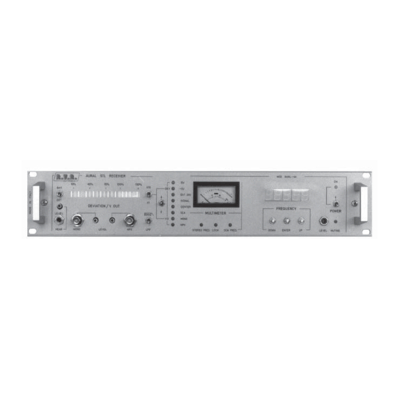
- Page 17 RXRL-NV/2 Technical and Maintenance Manual FRONT PANEL VIEW DESCRIPTION (FIG.1) LEVEL HEAR Hear level trimmer HEAR Hear jack MONO Mono output connector, BNC type MONO LEVEL TRIMMER Mono Level Trimmer STEREO LEVEL TRIMMER Stereo Level Trimmer Stereo output connector, BNC type...
- Page 18 RXRL-NV/2 Technical and Maintenance Manual MUTING Muting led indicator BAR/DOT Selector of operation mode (BAR/DOT) for deviation meter DEVIATION Deviation meter by "Led Diode Bar" x1/x10 Expansion of modulation meter scale: Pos. X1 - Full scale shows 100% Pos. X10 -...
- Page 19 RXRL-NV/2 Technical and Maintenance Manual FIG.1 R.V.R. Elettronica S.r.l. (Bo) Pag. 19...
- Page 20 RXRL-NV/2 Technical and Maintenance Manual REAR PANEL VIEW DESCRIPTION (FIG.2) PLUG A.C. power plug FUSE BLOCK Fuse Block & Voltage Changer. Use a small screwdriver to change fuse or volt age setting. Turn block and place desired operating voltage next to arrow...
- Page 21 RXRL-NV/2 Technical and Maintenance Manual FIG.2 R.V.R. Elettronica S.r.l. (Bo) Pag. 21...
- Page 22 RXRL-NV/2 Technical and Maintenance Manual TOP VIEW DESCRIPTION (FIG.3) ....Modulation Meter & Mono/Mpx Output Board ....Front-End & Mixer ....Anameter Card ....C.P.U....Transformer ....Doubler ....Power Supply ....Supply Socket ....R.F. Cavity ....Fan ....
- Page 23 RXRL-NV/2 Technical and Maintenance Manual FIG.3 R.V.R. Elettronica S.r.l. (Bo) Pag. 23...
- Page 24 RXRL-NV/2 Technical and Maintenance Manual FIG.4 R.V.R. Elettronica S.r.l. (Bo) Pag. 24...
- Page 25 3.3 INSTALLATION To install the RXRL-NV/2 receiver, carry out the following procedure: This receiver is able to operate from 4 different supply voltages: 100, 120, 220 or 240Vac, at 50-60Hz.
- Page 26 RXRL-NV/2 Technical and Maintenance Manual that the oscillator has locked to the operating frequency displayed. The display has five digits, 4 before the decimal point representing (from left to right) thousands of MHz, hundreds of MHz, tens of MHz and MHz; and 1 after the decimal point representing hundreds of KHz.
- Page 27 RXRL-NV/2 Technical and Maintenance Manual red led, indicating 100% deviation (equivalent to 100 KHz). With the DOT/BAR switch in the bar position, all the green leds and first red led will be on. Check that the audio analyzer reads +13dBm.
- Page 28 RXRL-NV/2 Technical and Maintenance Manual INSTRUMENT MODEL SPECIFICATIONS Non-inductive Bird 50 Ohm P > 5W dummy load Spectrum Analyzer Advantest 10KHz - 3.5GHz Mod. R4141D F.M. Modulation Meter Rohde Schwarz Mod. F.A.M. Digital Multimeter Metrix Power Meter Hewlett Packard Mod. 435B Stereo Decoder A.E.V.
- Page 29 MAINTENANCE LEVEL 1 4.2 ROUTINE MAINTENANCE The only routine maintenance required by the RXRL-NV/2 is the periodic replacement of the cooling fan and the removal of accumulated dust. The period between such action will depend on ambient operating conditions such as temperature, air-borne dust levels and humidity.
- Page 30 RXRL-NV/2 Technical and Maintenance Manual Disconnect connector CN1 connecting the Anameter card to the Audio Process card. Undo the nut holding the selector switch in place on the front panel. Unscrew the nuts holding the card to the meter. Remove the card with great care.
- Page 31 RXRL-NV/2 Technical and Maintenance Manual Desolder the power cable. Unscrew the Front-End/Mixer from the cover of the metal container protecting the Audio Process and 70MHz IF cards. Remove the Front-End/Mixer with great car 4.8 P.L.L. REPLACEMENT Open the top cover of the unit.
- Page 32 RXRL-NV/2 Technical and Maintenance Manual 4.11 70MHz IF CARD REPLACEMENT Open the top cover of the unit. Open the cover of the metal container which protects the Audio Process card and the 70MHz IF card and disconnect the Front-End, the Mixer and Doubler connectors fixed to the cover.
- Page 33 RXRL-NV/2 Technical and Maintenance Manual Unscrew the R.F. Cavity from the cover of the metal container which protects the Audio Process card and the 70MHz IF card. Remove the R.F. Cavity with great care. SECTION 5 CALIBRATION PROCEDURE OF R.V.R. Elettronica S.r.l. (Bo)
- Page 34 RXRL-NV/2 Technical and Maintenance Manual MODULES 5.1 INTRODUCTION TO ENSURE AN ACCURATE CALIBRATION OF THE RECEIVER, ALLOW THE UNIT TO REACH NORMAL OPERATING TEMPERATURE BEFORE CALIBRATION 5.2 CALIBRATION OF THE R.F. CAVITY To carry out this procedure, connect the transmitter and receiver as showed in SETUP 1 (Fig.5):...
- Page 35 RXRL-NV/2 Technical and Maintenance Manual Use an R.F. signal generator to inject a -47 dBm signal into the R.F. input of the receiver. SETUP 2 / FIG. 6 Using a frequency meter, check the accuracy of the 10.7 MHz IF (10.700 MHz is acceptable).
- Page 36 RXRL-NV/2 Technical and Maintenance Manual to reduce excessively the amplitude of the 10.7 MHz IF signal. 5.5 CALIBRATION OF THE MUTING CARD To carry out this procedure, configure the unit as detailed in SETUP 4 (Fig.8). Inject a -83 dBm signal into the R.F. input of the receiver.
- Page 37 RXRL-NV/2 Technical and Maintenance Manual Use the Modmeter calibration procedure to ensure that the readings are correct. It is essential to calibrate the MONO signal before being able to accurately measure MPX. 10) Configure the unit as detailed in SETUP 5 (Fig.9).
- Page 38 RXRL-NV/2 Technical and Maintenance Manual and R/L). 18) Inject a carrier at the receiver’s operating frequency, modulated by a 400 Hz tone with a deviation of ±100 KHz. 19) If necessary, adjust R71 to improve the stereo separation, using the procedure described in step 16.
- Page 39 RXRL-NV/2 Technical and Maintenance Manual Adjust trimmer R28, situated on the Audio Process card, to obtain a reading of 0 dBm. Adjust R15 so that the first red led of the SETUP 7 / FIG. 11 bar-graph display switches on.
- Page 40 RXRL-NV/2 Technical and Maintenance Manual red led switches on (corresponding to the 100% mark). 5.10 CALIBRATION OF THE POWER SUPPLY This module does not require calibration. 5.11 CALIBRATION OF THE VCO To calibrate the VCO, carry out the following procedure: Connect the positives probe of a voltmeter to the glass capacitor P2 (connected to the varicap) and the negative probe to ground.
- Page 41 LINK 6.1 INTRODUCTION This chapter details the alignment procedure for the PTRL-NV/2 (or PTRL- NV/2/HP) transmitter and the RXRL-NV/2 receiver. 6.2 FREQUENCY ALIGNMENT The operating frequency of the complete radio link (TX+RX) is set using a frequency meter to measure the frequency output by the transmitter and the frequency after the second conversion of the receiver.
- Page 42 RXRL-NV/2 Technical and Maintenance Manual Switch on the transmitter and wait until it has locked to its operating frequency i.e. the UNLOCK light goes out. Connect a 30dB attenuator between the R.F. Output and 50 Ohm and Frequency Counter. Use the meter selector to select direct power measurement, FWD.
- Page 43 Inject the resultant R.F. signal into the receiver input. Using the "FAM" modulation analyzer, check that the S/N ratio or the RXRL-NV/2 receiver is better than 65dB, referred to a deviation ±100KHz. Connect the instruments as shown in SETUP B2 (Fig.10) to make the STEREO measurement.
- Page 44 Use the modulation analyzer to make the S/N measurement and check that the figure is better than 60dB (measured on each demodulated and de-emphasize single channel) for the RXRL-NV/2 receiver. 6.4 STEREO SEPARATION Stereo separation is measured using a stereo coder, a stereo demodulator and an audio analyzer.
- Page 45 RXRL-NV/2 Technical and Maintenance Manual CASE B - Should the new frequency fall outside the range of receiver's R.F. Power Amplifier Stage (and relative receiver's Front-End/ Mixer) CASE A Should the new frequency fall within the range of receiver's R.F. Power...
- Page 46 RXRL-NV/2 Technical and Maintenance Manual Configure the modulation analyzer to read deviation. Check that the deviation reading for the PTRL-NV/2 (PTRL-NV/2/HP) is 100KHz and if not, adjust trimmer R8 (inside the VCO) to obtain (Do this step for both MONO and STEREO inputs).
- Page 47 RXRL-NV/2 Technical and Maintenance Manual INDICE Istruzioni Preliminari ed Informazioni di Garanzia Pag. 49 Regole di Sicurezza Pag. 51 CAPITOLO 1 Descrizione Generale Pag. 54 Specifiche Elettriche (Tabella A) Pag. 56 Specifiche Dimensionali e Ambientali (Tabella B) Pag. 57 CAPITOLO 2 Descrizione Elettrica Pag.
- Page 48 RXRL-NV/2 Technical and Maintenance Manual C.P.U. Pag. 102 Modmeter Card Pag. 111 Anameter Card Pag. 116 Audio Process Card Pag. 124 P.L.L. Card Pag. 130 V.C.O. Pag. 135 I.F. 70MHz Card (I.F. 10.7MHz) Pag. 140 Front-End e Mixer Pag. 146 Doubler Pag.
- Page 49 RXRL-NV/2 Technical and Maintenance Manual ISTRUZIONI PRELIMINARI E INFORMAZIONI DI GARANZIA Si prega di osservare le necessarie precauzioni di sicurezza quando si usa questa apparecchiatura. Questa macchina presenta al suo interno correnti pericolose e alte tensioni. Questo manuale è stato concepito per fornire una guida generale per coloro che hanno necessità...
- Page 50 RXRL-NV/2 Technical and Maintenance Manual La garanzia entrerà in vigore dalla data di fattura per il periodo di garanzia di costruzione. Per reclamare i propri diritti con questa garanzia: Contattare il rivenditore o il distributore dove avete acquistato la macchina. Descrivere il problema e chiedere se è in grado di fornirvi una facile soluzione.
- Page 51 La società R.V.R. ELETTRONICA s.r.l. non sarà responsabile per lesioni o danni risultanti da procedure improprie o dall’uso di personale inesperto o non correttamente addestrato all’adempimento di tali mansioni.
- Page 52 RXRL-NV/2 Technical and Maintenance Manual Trattamento degli shock elettrici 1) Se la vittima ha perso conoscenza seguire i principi di primo soccorso riportati nei punti A-B-C. POSIZIONARE LA VITTIMA SDRAIATA SULLA SCHIENA SU UNA SUPERFICIE RIGIDA A VIE AEREE B RESPIRAZIONE...
- Page 53 RXRL-NV/2 Technical and Maintenance Manual PRIMO SOCCORSO Il personale impegnato nell’installazione, nel funzionamento, nella manutenzione o assistenza di questo dispositivo ha la necessità di avere familiarità con la teoria e le pratiche di primo soccorso. La relazione seguente non rappresenta una guida completa delle procedure di primo soccorso, ma è...
- Page 54 DESCRIZIONE GENERALE 1.1 DESCRIZIONE ESTERNA Il recevitore RXRL-NV/2 è stato realizzato in un contenitore rack 19" 2U, internamente assemblato con moduli montati e fissati sul fondo della macchina. Ciò consente una facile rimozione e sostituzione dei moduli stessi. Nel pannello frontale sono i connettori d’uscita audio con le relative regolazioni del livello d’uscita (Mono e MPX) e i misuratori dei parametri...
- Page 55 RXRL-NV/2 Technical and Maintenance Manual Fare riferimento alla Tabella (a) per le caratteristiche elettriche e alla Tabella (B) per quelle dimensionali e ambientali. R.V.R. Elettronica S.r.l. (Bo) Pag. 55...
- Page 56 RXRL-NV/2 Technical and Maintenance Manual TABELLA A SPECIFICHE ELETTRICHE Alimentazione A.C. 100, 120, 220 e 240 V, ±10% 50-60 Hz, singola fase 22W 24Vdc opzionale Raffreddamento Ventilazione forzata Frequenza di lavoro da 1400 a 2600 MHz in sotto-bande di 50MHz Sensibilità...
- Page 57 RXRL-NV/2 Technical and Maintenance Manual TABELLA B SPECIFICHE DIMENSIONALI E AMBIENTALI Dimensioni del rack 82mm (3,22") H 326mm (12,83") D 445mm (17,51") W Dimensioni del pannello 483mm (19") W 88mm (3,47") H Temperatura di lavoro da -10°C a +50°C Umidità...
- Page 58 Questo circuito è costituito da una scheda fissata sulla destra del fondo dell’apparecchiatura (7 Fig.3). L’alimentatore del RXRL-NV/2 è predisposto per funzionare con una tensione di alimentazione di 100V, 120V, 220V e 240V ±10% (24Vdc opzionale), 50-60Hz. L’alimentatore fornisce le tensioni stabilizzate necessarie al funzionamento dei vari moduli che compongono l’RXRL-NV/2.
- Page 59 RXRL-NV/2 Technical and Maintenance Manual uno per il segnale MPX. Un interruttore permette di selezionare il guadagno del misuratore a due livelli (10% e 100%) per ottenere una misura più precisa per bassi livelli di deviazione (es. SCA, RDS, toni pilota).
- Page 60 RXRL-NV/2 Technical and Maintenance Manual E’ una scheda fissata nella parte sinistra del fondo della macchina (13 Fig.3). Su tale scheda è contenuto il VCO racchiuso in un contenitore metallico (12 Fig.3). Questa scheda riceve il segnale binario equivalente alla frequenza impostata proveniente dalla CPU.
- Page 61 RXRL-NV/2 Technical and Maintenance Manual D E S C R I Z I O N E D E L P A N N E L L O F R O N T A L E ( F I G . 1 )
- Page 62 RXRL-NV/2 Technical and Maintenance Manual HEAR Presa Jack per inserzione cuffia MONO Connettore BNC d’uscita del segnale Mono REG. MONO Trimmer di regolazione del livello d’uscita Mono REG. MPX Trimmer di regolazione del livello d’uscita Stereo Connettore BNC d’uscita del...
- Page 63 RXRL-NV/2 Technical and Maintenance Manual stessa LEVEL MUTING Trimmer di regolazione del livello del muting MUTING Led che indica l’attivazione del muting in quanto il livello del segnale d’ingresso è sceso sotto soglia stabilita BAR/DOT Selettore del modo (BAR/DOT) per l’indicatore di modulazione...
- Page 64 RXRL-NV/2 Technical and Maintenance Manual FIG.1 R.V.R. Elettronica S.r.l. (Bo) Pag. 64...
- Page 65 RXRL-NV/2 Technical and Maintenance Manual PLUG Presa alimentazione Vac BLOCCO FUSIBILI Blocco fusibili e cambia tensioni REMOTE CONTROL (Opzionale) Connettore DB9 per il controllo del ricevitore a distanza MORSETTO ROSSO (Opzionale) Morsetto positivo per l’alimentazione esterna a 24V MORSETTO NERO...
- Page 66 RXRL-NV/2 Technical and Maintenance Manual FIG.2 R.V.R. Elettronica S.r.l. (Bo) Pag. 66...
- Page 67 RXRL-NV/2 Technical and Maintenance Manual ....Front-End e Mixer ....Scheda Anameter ....C.P.U....Trasformatore ....Doubler ....Alimentatore ....Presa d’alimentazione ....Filtro Cavità ....Ventola ....Connettore d’ingresso R.F....V.C.O....Scheda P.L.L. CAPITOLO 3 PROCEDURE PER R.V.R.
- Page 68 RXRL-NV/2 Technical and Maintenance Manual FIG.3 R.V.R. Elettronica S.r.l. (Bo) Pag. 68...
- Page 69 RXRL-NV/2 Technical and Maintenance Manual FIG.4 R.V.R. Elettronica S.r.l. (Bo) Pag. 69...
- Page 70 3.3 INSTALLAZIONE Per eseguire l’installazione del ricevitore RXRL-NV/2 occorre eseguire le seguenti operazioni: Questo ricevitore ha la possibilità di funzionare con 4 differenti tensioni di alimentazione: 100, 120, 220 o 240Vac, a 50-60Hz.
- Page 71 RXRL-NV/2 Technical and Maintenance Manual all’ultima frequenza impostata. Entro 30 sec. si dovrà verificare l’accensione del led verde LOCK: questo indica che l’oscillatore è agganciato sulla frequenza di lavoro impostata. Il display è composto da cinque cifre, di cui una sempre alla destra...
- Page 72 RXRL-NV/2 Technical and Maintenance Manual Verificare che lo strumento di misura analogico (21 Fig.1) esegua la lettura di 1mV. Selezionare tramite il selettore (20 Fig.1) la misura CENTER e verificare la centratura del segnale ricevuto. Verifica misuratore di deviazione. Porre il deviatore di selezione del fondo della scala dell’indicatore di modulazione (19 Fig.1) su X1.
- Page 73 RXRL-NV/2 Technical and Maintenance Manual TABELLA C STRUMENTAZIONE CONSIGLIATA PER I TEST STRUMENTO MODELLO SPECIFICHE Non-inductive Bird 50 Ohm P > 5W dummy load Spectrum Analyzer Advantest 10KHz - 3.5GHz Mod. R4141D F.M. Modulation Meter Rohde Schwarz Mod. F.A.M. Digital Multimeter...
- Page 74 PRIMO LIVELLO DI MANUTENZIONE 4.2 MANUTENZIONE ORDINARIA L’unica manutenzione di cui necessita il RXRL-NV/2 è la periodica sostituzione delle ventole e la relativa pulizia da tracce di polvere eventualmente accumulate al suo interno. Tale periodicità dipende dalle condizioni di funzionamento della macchina, temperatura ambiente, livello di polvere nell’aria, umidità.
- Page 75 RXRL-NV/2 Technical and Maintenance Manual Togliere il coperchio superiore della macchina. Svitare le viti di fissaggio del pannello frontale. Disconnettere il connettore CN1 che collega l’Anameter card con la Audio Process card. Svitare il dado dello Switch Selector posto sul pannello frontale.
- Page 76 RXRL-NV/2 Technical and Maintenance Manual Togliere il coperchio superiore della macchina. Disconnettere i connettori CN1, CN2 e CN3 e dissaldare il filo di alimentazione. Svitare il Front-End/Mixer dal coperchio della scatola metallica che protegge le schede Audio Process e IF 70MHz.
- Page 77 RXRL-NV/2 Technical and Maintenance Manual Estrarre la scheda con molta cautela. 4.11 SOSTITUZIONE DELLA IF 70MHz CARD Togliere il coperchio superiore della macchina. Disconnettere i connettori del Front-End, del Mixer, del Doubler e togliere il coperchio della scatola metallica che protegge la scheda Audio Process e la scheda IF 70MHz.
- Page 78 RXRL-NV/2 Technical and Maintenance Manual Aprire il coperchio superiore della macchina. Disconnettere i connettori CN1 e CN2 del Filtro Cavità. Svitare il Doubler dal coperchio metallico della scheda Audio Process e della scheda IF 70MHz. Estrarre il Filtro Cavità con molta cautela.
- Page 79 RXRL-NV/2 Technical and Maintenance Manual PROCEDURA PER LA TARATURA 5.1 INTRODUZIONE PER OTTENERE UNA BUONA TARATURA E' NECESSARIO PORTARE IL DISPOSITIVO ALLA TEMPERATURA DI LAVORO. 5.2 TARATURA DEL FILTRO CAVITA' Per effettuare questa taratura occorre collegare l’equipaggiamento come mostrato nel SETUP 1 (Fig.5): SETUP 1 / FIG.
- Page 80 RXRL-NV/2 Technical and Maintenance Manual SETUP 2 / FIG. 6 Iniettare nell’ingresso RF del ricevitore un segnale di livello -47dBm alla frequenza pari a quella di lavoro del ricevitore, tramite il generatore di segnali RF. Verificare tramite un frequenzimetro, la precisione della lettura della frequenza IF 10,7MHz (accettabile 10,700MHz).
- Page 81 RXRL-NV/2 Technical and Maintenance Manual ottimizzato quella MONO, risulta ottimizzata anche quella MPX (minore o uguale a 0,3%). In caso contrario si può agire su P1, TR1 TR2, tenendo presente di non diminuire troppo il livello d’ampiezza della IF 10,7MHz.
- Page 82 RXRL-NV/2 Technical and Maintenance Manual Verificare che il livello di +13dBm sia ancora presente, in caso contrario agire ancora su R8. Verificare tramite le procedure di taratura della Modmeter card che le misure da essa effettuate siano corrette. E’ fondamentale effettuare prima la taratura del segnale MONO per poter ottenere una misura corretta di SCA.
- Page 83 RXRL-NV/2 Technical and Maintenance Manual agire su R80 e R65, tenendo presente che la separazione stereo tra due canali deve essere bilanciata (±2 o 3 dB tra L/R e R/L). 18) Iniettare un segnale con portante alla frequenza di lavoro e con modulante a 400Hz con deviazione di ±100KHz.
- Page 84 RXRL-NV/2 Technical and Maintenance Manual SETUP 7 / FIG. 11 Regolare il trimmer R28 posto sulla scheda Audio Process per ottenere 0dBm. Agire su R15 per ottenere l’accensione del primo led rosso della barra di led della Modmeter Card. Collegare l’equipaggiamento come mostrato nel SETUP 8 (Fig.12): Porre il selettore della barra di led sulla posizione x1, e iniettare SETUP 8 / FIG.
- Page 85 RXRL-NV/2 Technical and Maintenance Manual Regolare il trimmer R4 sulla scheda Modmeter per l’accensione del 1° led rosso (corrispondente alla scritta 100%). 5.10 TARATURA DEL POWER SUPPLY Questo dispositivo non necessita di operazioni di taratura. 5.11 TARATURA DEL VCO Per effettuare la taratura del VCO occorre eseguire le seguenti...
- Page 86 RADIO 6.1 INTRODUZIONE Questo capitolo presenta le procedure di allineamento tra il trasmettitore PTRL-NV/2 (o PTRL-NV/2/HP) e il ricevitore RXRL-NV/2 6.2 ALLINEAMENTO IN FREQUENZA La frequenza del ponte radio completo (TX+RX) viene allineata usando un frequenzimetro per misurare la frequenza di uscita del trasmettitore e la frequenza della seconda conversione del ricevitore.
- Page 87 RXRL-NV/2 Technical and Maintenance Manual Accendere il trasmettitore e attendere fino a che non è avvenuto l’aggancio sulla frequenza di lavoro e non si è spenta la spia U N - LOCK. Selezionare sul pannello frontale con il meter selector la misura FWD della potenza diretta.
- Page 88 100µV (-67dBm) da inviare al ingresso RF del ricevitore. Modulare la portante RF con un tono a 400Hz deviato a ±100KHz. Verificare sull’analizzatore di modulazione, che il rapporto segnale rumore per il ricevitore RXRL-NV/2 sia migliore di 65dB. Connettere gli strumenti come mostrato nel SETUP B2 (Fig.10) per effettuare la misura del segnale STEREO.
- Page 89 RXRL-NV/2 Technical and Maintenance Manual Predisporre il generatore di segnali affinché emetta un segnale con un livello di 1mV (-47dBm) da inviare all'ingresso del ricevitore. Effettuare la misura del rapporto segnale rumore sull’analizzatore di modulazione, e verificare che sia migliore di 60dB per ogni singolo canale demodulato e deenfatizzato.
- Page 90 RXRL-NV/2 Technical and Maintenance Manual CASO B - La nuova frequenza non ricade nel range di lavoro del finale del trasmettitore o del Front-End/Mixer del ricevitore. CASO A Nel caso in cui la nuova frequenza ricada nel range di lavoro del finale...
- Page 91 RXRL-NV/2 Technical and Maintenance Manual deviazione. Verificare che il valore della deviazione letto sia 100KHz per il PTRL-NV/2 (o PTRL-NV/2/HP). In caso contrario agire sul trimmer R8 contenuto all’interno VCO (effettuare l’operazione sia per l’ingresso MONO che STEREO). Predisporre ora l’analizzatore in modo da ottenere la lettura della distorsione (con de-enfasi di 50µSec per la versione Europea e di...
- Page 92 RXRL-NV/2 Technical and Maintenance Manual APPENDIX A CIRCUIT DIAGRAMS, LAYOUTS AND BILLS OF MATERIAL This section contains circuit diagrams, layouts and bills of material of the modules which composing the equipment. For more information about each module see as reference Section 2.
- Page 93 RXRL-NV/2 Technical and Maintenance Manual WIRING DIAGRAM / DIAGRAMMA DI CONNESSIONE DELLE SCHEDE R.V.R. Elettronica S.r.l. (Bo) Pag. 93...
- Page 94 RXRL-NV/2 Technical and Maintenance Manual POWER SUPPLY Circuit Diagram Pag. 95 Bill of Material Pag. 96 Component Layout Pag. 97 POWER SUPPLY Schema Elettrico Pag. 95 Lista dei Componenti Pag. 96 Piano di Montaggio Pag. 97 R.V.R. Elettronica S.r.l. (Bo)
- Page 95 RXRL-NV/2 Technical and Maintenance Manual R.V.R. Elettronica S.r.l. (Bo) Pag. 95...
- Page 96 RXRL-NV/2 Technical and Maintenance Manual Power Supply Card Bill Of Materials/Lista Componneti Pag. 1 Item Quantity Reference Part Description Part Order Code _________________________________________________________________________________________________ 1 R3 RESISTOR 1/4W 5% RSC1/4JH0220 1 R4 RESISTOR 1/4W 5% RSC1/4JK02,2 5 C3,C4,C11, 100nF CERAMIC CAPACITOR...
- Page 97 RXRL-NV/2 Technical and Maintenance Manual R.V.R. Elettronica S.r.l. (Bo) Pag. 97...
- Page 98 RXRL-NV/2 Technical and Maintenance Manual MUTING CARD Circuit Diagram Pag. 99 Bill of Material Pag. 100 Component Layout Pag. 101 MUTING CARD Schema Elettrico Pag. 90 Lista dei Componenti Pag. 100 Piano di Montaggio Pag. 101 R.V.R. Elettronica S.r.l. (Bo)
- Page 99 RXRL-NV/2 Technical and Maintenance Manual R.V.R. Elettronica S.r.l. (Bo) Pag. 99...
- Page 100 RXRL-NV/2 Technical and Maintenance Manual Muting Card Bill Of Materials/Lista Componneti Pag. 1 Item Quantity Reference Part Description Part Order Code _________________________________________________________________________________________________ 1 R1 RESISTOR 1/4W 5% RSC1/4JH0270 1 R2 TRIMMER MULTIGIRI RVTMULAK0005 1 CN0 10 PIN FLAT CONN. F 2*5 PER FLAT C. CNTFVLFC10P...
- Page 101 RXRL-NV/2 Technical and Maintenance Manual R.V.R. Elettronica S.r.l. (Bo) Pag. 101...
- Page 102 RXRL-NV/2 Technical and Maintenance Manual C.P.U. Block Diagrm Pag. 103 Circuit Diagram Pag. 104 Bill of Material Pag. 106 Component Layout Pag. 108 C.P.U. Diagramma a Blocchi Pag. 103 Schema Elettrico Pag. 104 Lista dei Componenti Pag. 106 Piano di Montaggio Pag.
- Page 103 RXRL-NV/2 Technical and Maintenance Manual R.V.R. Elettronica S.r.l. (Bo) Pag. 103...
- Page 104 RXRL-NV/2 Technical and Maintenance Manual R.V.R. Elettronica S.r.l. (Bo) Pag. 104...
- Page 105 RXRL-NV/2 Technical and Maintenance Manual R.V.R. Elettronica S.r.l. (Bo) Pag. 105...
- Page 106 RXRL-NV/2 Technical and Maintenance Manual C.P.U. Bill of Materials/Lista Componenti Pag. 1 Item Quantity Reference Part Description Part Order Code __________________________________________________________________________________________________ 2 R1,R2 RESISTOR 1/4W 5% RSC1/4JH0680 1 R3 RESISTOR 1/4W 5% RSC1/4JK0010 2 R4,R5 RESISTOR 1/4W 5% RSC1/4JK0033 1 C1...
- Page 107 RXRL-NV/2 Technical and Maintenance Manual C.P.U. Bill of Materials/Lista Componenti Pag. 2 Item Quantity Reference Part Description Part Order Code __________________________________________________________________________________________________ 2 ZC7,ZC8 ZOC16 ZOCCOLO INTEGRATO 16P ZIN16 3 ZC9,ZC10, ZOC28 ZOCCOLO INTEGRATO 28P ZIN28 ZC11 2 ZC12,ZC13 ZOC40 ZOCCOLO INTEGRATO 40P...
- Page 108 RXRL-NV/2 Technical and Maintenance Manual R.V.R. Elettronica S.r.l. (Bo) Pag. 108...
- Page 109 RXRL-NV/2 Technical and Maintenance Manual R.V.R. Elettronica S.r.l. (Bo) Pag. 109...
- Page 110 RXRL-NV/2 Technical and Maintenance Manual R.V.R. Elettronica S.r.l. (Bo) Pag. 110...
- Page 111 RXRL-NV/2 Technical and Maintenance Manual MODMETER CARD Circuit Diagram Pag. 112 Bill of Material Pag. 113 Component Layout Pag. 115 MODMETER CARD Schema Elettrico Pag. 112 Lista dei Componenti Pag. 113 Piano di Montaggio Pag. 115 R.V.R. Elettronica S.r.l. (Bo)
- Page 112 RXRL-NV/2 Technical and Maintenance Manual R.V.R. Elettronica S.r.l. (Bo) Pag. 112...
- Page 113 RXRL-NV/2 Technical and Maintenance Manual Modmeter Card Bill Of Materials/Lista Componneti Pag. 1 Item Quantity Reference Part Description Part Order Code _________________________________________________________________________________________________ 3 R19,R22,R45 RESISTOR 1/4W 5% RSC1/4JH0010 5 R17,R18, 15 RESISTOR 1/4W 5% RSC1/4JH0015 R21,R25,R28 1 R37 RESISTOR 1/4W 5%...
- Page 114 RXRL-NV/2 Technical and Maintenance Manual Modmeter Card Bill Of Materials/Lista Componneti Pag. 2 Item Quantity Reference Part Description Part Order Code _________________________________________________________________________________________________ 1 C19 47nF CERAMIC CAPACITOR CKM473BK600P 2 C13,C17 0.1µF CERAMIC CAPACITOR CKM104BK600P 9 C4,C5,C9, 10µF ELECTROLYTIC CAPACITOR CEA106AM350...
- Page 115 RXRL-NV/2 Technical and Maintenance Manual R.V.R. Elettronica S.r.l. (Bo) Pag. 115...
- Page 116 RXRL-NV/2 Technical and Maintenance Manual ANAMETER CARD Anameter Card 1 Circuit Diagram Pag. 117 Anameter Card 1 Bill of Material Pag. 118 Anameter Card 1 Component Layout Pag. 120 Anameter Card 2 Circuit Diagram Pag. 121 Anameter Card 2 Bill of Material Pag.
- Page 117 RXRL-NV/2 Technical and Maintenance Manual R.V.R. Elettronica S.r.l. (Bo) Pag. 117...
- Page 118 RXRL-NV/2 Technical and Maintenance Manual Anameter Card 1 Bill Of Materials/Lista Componneti Pag. 1 Item Quantity Reference Part Description Part Order Code _________________________________________________________________________________________________ 2 R5,R6 RESISTOR 1/4W 5% RSC1/4JH0018 2 R42,R43 RESISTOR 1/4W 5% RSC1/4JH0022 2 R13,R14 RESISTOR 1/4W 5%...
- Page 119 RXRL-NV/2 Technical and Maintenance Manual Anameter Card 1 Bill Of Materials/Lista Componneti Pag. 2 Item Quantity Reference Part Description Part Order Code _________________________________________________________________________________________________ 5 C18,C19, 0.1µF CERAMIC CAPACITOR CKM104BK600P C20,C21,C22 1 C17 4.7µF ELECTROLYTIC CAPACITOR CEA475AM350 3 C3,C15,C16 10µF ELECTROLYTIC CAPACITOR CEA106AM350 3 C4,C5,C6 47µF...
- Page 120 RXRL-NV/2 Technical and Maintenance Manual R.V.R. Elettronica S.r.l. (Bo) Pag. 120...
- Page 121 RXRL-NV/2 Technical and Maintenance Manual R.V.R. Elettronica S.r.l. (Bo) Pag. 121...
- Page 122 RXRL-NV/2 Technical and Maintenance Manual Anameter Card 2 Bill Of Materials/Lista Componneti Pag. 1 Item Quantity Reference Part Description Part Order Code _________________________________________________________________________________________________ 3 R61,R62,R63 RESISTOR 1/4W 5% RSC1/4JK0001 1 CN3 26P CONN. CONN. M 2*13 P 2.54 CNTMCSFC26P 1 SW1 2V 2P 0C DEV.
- Page 123 RXRL-NV/2 Technical and Maintenance Manual R.V.R. Elettronica S.r.l. (Bo) Pag. 123...
- Page 124 RXRL-NV/2 Technical and Maintenance Manual AUDIO PROCESS CARD Circuit Diagram Pag. 125 Bill of Material Pag. 126 Component Layout Pag. 129 AUDIO PROCESS CARD Schema Elettrico Pag. 125 Lista dei Componenti Pag. 126 Piano di Montaggio Pag. 129 R.V.R. Elettronica S.r.l. (Bo)
- Page 125 RXRL-NV/2 Technical and Maintenance Manual R.V.R. Elettronica S.r.l. (Bo) Pag. 125...
- Page 126 RXRL-NV/2 Technical and Maintenance Manual Audio Process Card Bill Of Materials/Lista Componneti Pag. 1 Item Quantity Reference Part Description Part Order Code _________________________________________________________________________________________________ 1 R47 RESISTOR 1/4W 5% RSC1/4JH0010 19 R48,R49, 22 RESISTOR 1/4W 5% RSC1/4JH0022 R51,R52,R54, R57,R66,R67, R77,R78,R82, R83,R87,R88,...
- Page 127 RXRL-NV/2 Technical and Maintenance Manual Audio Process Card Bill Of Materials/Lista Componneti Pag. 2 Item Quantity Reference Part Description Part Order Code _________________________________________________________________________________________________ 2 R5,R21 150K RESISTOR 1/4W 5% RSC1/4JK0150 1 R101 470K RESISTOR 1/4W 5% RSC1/4JK0470 1 R37 RESISTOR 1/4W 5%...
- Page 128 RXRL-NV/2 Technical and Maintenance Manual Audio Process Card Bill Of Materials/Lista Componneti Pag. 3 Item Quantity Reference Part Description Part Order Code _________________________________________________________________________________________________ 3 CN1,CN2, 16P CONN. CONN. M 2*8 P 2.54 CNTMCSFC16P 2 CN3,CN5 26P CONN. CONN. M 2*13 P 2.54...
- Page 129 RXRL-NV/2 Technical and Maintenance Manual R.V.R. Elettronica S.r.l. (Bo) Pag. 129...
- Page 130 RXRL-NV/2 Technical and Maintenance Manual P.L.L. CARD Circuit Diagram Pag. 131 Bill of Material Pag. 132 Component Layout Pag. 134 P.L.L. CARD Schema Elettrico Pag. 131 Lista dei Componenti Pag. 132 Piano di Montaggio Pag. 134 R.V.R. Elettronica S.r.l. (Bo)
- Page 131 RXRL-NV/2 Technical and Maintenance Manual R.V.R. Elettronica S.r.l. (Bo) Pag. 131...
- Page 132 RXRL-NV/2 Technical and Maintenance Manual P.L.L. Card Bill Of Materials/Lista Componneti Pag. 1 Item Quantity Reference Part Description Part Order Code _________________________________________________________________________________________________ 2 R27,R30 RESISTOR 1/4W 5% RSC1/4JH0022 1 R14 RESISTOR 1/4W 5% RSC1/4JH0150 3 R21,R22,R23 RESISTOR 1/4W 5% RSC1/4JH0330...
- Page 133 RXRL-NV/2 Technical and Maintenance Manual P.L.L. Card Bill Of Materials/Lista Componneti Pag. 2 Item Quantity Reference Part Description Part Order Code _________________________________________________________________________________________________ 2 CN3,CN4 CON. SMB A CRIMP. RG188 CNTSMBFCVD 1 X1 Q4MHZ CRYSTAL QRZ4HC18 3 D1,D2,D3 1N4148 SILICON DIODE...
- Page 134 RXRL-NV/2 Technical and Maintenance Manual R.V.R. Elettronica S.r.l. (Bo) Pag. 134...
- Page 135 RXRL-NV/2 Technical and Maintenance Manual V.C.O. CARD Circuit Diagram Pag. 136 Bill of Material Pag. 137 Component Layout Pag. 139 V.C.O. CARD Schema Elettrico Pag. 136 Lista dei Componenti Pag. 137 Piano di Montaggio Pag. 139 R.V.R. Elettronica S.r.l. (Bo)
- Page 136 RXRL-NV/2 Technical and Maintenance Manual R.V.R. Elettronica S.r.l. (Bo) Pag. 136...
- Page 137 RXRL-NV/2 Technical and Maintenance Manual V.C.O. Card Bill Of Materials/Lista Componneti Pag. 1 Item Quantity Reference Part Description Part Order Code _________________________________________________________________________________________________ 1 R6 RESISTOR 1/4W 5% RSC1/4JH0039 1 R9 RESISTOR 1/4W 5% RSC1/4JH0100 1 R7 RESISTOR 1/4W 5% RSC1/4JH0120...
- Page 138 RXRL-NV/2 Technical and Maintenance Manual V.C.O. Card Bill Of Materials/Lista Componneti Pag. 2 Item Quantity Reference Part Description Part Order Code _________________________________________________________________________________________________ 1 L3 L35RVR 3 SP DIA 5 1 L2 LINK LINK FILO ARG. 1mm CAVARG1000 1 CN4 BNC C.S.
- Page 139 RXRL-NV/2 Technical and Maintenance Manual R.V.R. Elettronica S.r.l. (Bo) Pag. 139...
- Page 140 RXRL-NV/2 Technical and Maintenance Manual I.F. 70MHz CARD (I.F. 10.7MHz CARD) Circuit Diagram Pag. 141 Bill of Material Pag. 142 Component Layout Pag. 145 I.F. 70MHz CARD (I.F. 10.7MHz CARD) Schema Elettrico Pag. 141 Lista dei Componenti Pag. 142 Piano di Montaggio Pag.
- Page 141 RXRL-NV/2 Technical and Maintenance Manual R.V.R. Elettronica S.r.l. (Bo) Pag. 141...
- Page 142 RXRL-NV/2 Technical and Maintenance Manual I.F. 70MHz Card Bill Of Materials/Lista Componneti Pag. 1 Item Quantity Reference Part Description Part Order Code _________________________________________________________________________________________________ 3 R42,R50,R60 RESISTOR 1/4W 5% RSC1/4JH0010 1 R58 RESISTOR 1/4W 5% RSC1/4JH0022 1 R37 RESISTOR 1/4W 5%...
- Page 143 RXRL-NV/2 Technical and Maintenance Manual I.F. 70MHz Card Bill Of Materials/Lista Componneti Pag. 2 Item Quantity Reference Part Description Part Order Code _________________________________________________________________________________________________ 5 C32,C38, 1nF CERAMIC CAPACITOR CKM102BK600P C45,C49,C58 1 C32' 1nFCH CERAMIC CHIP CAPACITOR CCC102AJ500 1 C39 CERAMIC CAPACITOR...
- Page 144 RXRL-NV/2 Technical and Maintenance Manual I.F. 70MHz Card Bill Of Materials/Lista Componneti Pag. 3 Item Quantity Reference Part Description Part Order Code _________________________________________________________________________________________________ 1 IC5 78L08 POS. STABILIZER 100mA CIL78L08 1 T6 BC237 NPN TRANSISTOR TRNBC237 2 T3,T4 2N2222 NPN RF TRANSISTOR...
- Page 145 RXRL-NV/2 Technical and Maintenance Manual R.V.R. Elettronica S.r.l. (Bo) Pag. 145...
- Page 146 RXRL-NV/2 Technical and Maintenance Manual FRONT-END & MIXER Circuit Diagram Pag. 147 Bill of Material Pag. 148 Component Layout Pag. 150 FRONT-END & MIXER Schema Elettrico Pag. 147 Lista dei Componenti Pag. 148 Piano di Montaggio Pag. 150 R.V.R. Elettronica S.r.l. (Bo)
- Page 147 RXRL-NV/2 Technical and Maintenance Manual R.V.R. Elettronica S.r.l. (Bo) Pag. 147...
- Page 148 RXRL-NV/2 Technical and Maintenance Manual Front-End & Mixer Bill Of Materials/Lista Componneti Pag. 1 Item Quantity Reference Part Description Part Order Code _________________________________________________________________________________________________ 3 R2A,R4A,R4 10CH CHIP RESISTOR RCC1/4JH0010 1 R2 33CH CHIP RESISTOR 1/4W RCC1/4JH0033 4 R1A,R1, 47CH CHIP RESISTOR 1/4W...
- Page 149 RXRL-NV/2 Technical and Maintenance Manual Front-End & Mixer Bill Of Materials/Lista Componneti Pag. 2 Item Quantity Reference Part Description Part Order Code _________________________________________________________________________________________________ 1 Q3 BD681 NPN DARLINGTON TRNBD681 2 Q1A,Q1 MGF1302-15 GAS-FET MGF1302-15 TRNMGF130215 14 ST2A,ST2, STRIP LINE STRIP LINE...
- Page 150 RXRL-NV/2 Technical and Maintenance Manual R.V.R. Elettronica S.r.l. (Bo) Pag. 150...
- Page 151 RXRL-NV/2 Technical and Maintenance Manual DOUBLER Circuit Diagram Pag. 152 Bill of Material Pag. 153 Component Layout Pag. 154 DOUBLER Schema Elettrico Pag. 152 Lista dei Componenti Pag. 153 Piano di Montaggio Pag. 154 R.V.R. Elettronica S.r.l. (Bo) Pag. 151...
- Page 152 RXRL-NV/2 Technical and Maintenance Manual R.V.R. Elettronica S.r.l. (Bo) Pag. 152...
- Page 153 RXRL-NV/2 Technical and Maintenance Manual Doubler Bill of Materials/Lista Componenti Pag. 1 Item Quantity Reference Part Description Part Order Code __________________________________________________________________________________________________ 4 R4,R5,R8, 100CH CHIP RESISTOR RCC1/4JH0100F 2 R3,R7 150CH CHIP RESISTOR RCC1/4JH0150F 2 R1,R9 1K5CH CHIP RESISTOR RCC1/4JH01,5 4 C1,C4,C11 1p5...
- Page 154 RXRL-NV/2 Technical and Maintenance Manual R.V.R. Elettronica S.r.l. (Bo) Pag. 154...
- Page 155 RXRL-NV/2 Technical and Maintenance Manual INVERTER CARD (OPTIONAL) Circuit Diagram Pag. 156 Bill of Material Pag. 157 Component Layout Pag. 158 INVERTER CARD (OPZIONALE) Schema Elettrico Pag. 156 Lista dei Componenti Pag. 157 Piano di Montaggio Pag. 158 R.V.R. Elettronica S.r.l. (Bo)
- Page 156 RXRL-NV/2 Technical and Maintenance Manual R.V.R. Elettronica S.r.l. (Bo) Pag. 156...
- Page 157 RXRL-NV/2 Technical and Maintenance Manual Inverter Card Bill Of Materials/Lista Componneti Pag. 1 Item Quantity Reference Part Description Part Order Code _________________________________________________________________________________________________ 1 R1 RESISTOR 1/4W 5% RSC1/4JK04,7 5 C11,C12, 1nFPAS CERAMIC THROUGH CAPAC. CDP102XK500 C13,C14,C15 3 C1,C4,C6 100nF CERAMIC CAPACITOR...
- Page 158 RXRL-NV/2 Technical and Maintenance Manual R.V.R. Elettronica S.r.l. (Bo) Pag. 158...
- Page 159 RXRL-NV/2 Technical and Maintenance Manual U.S.A. AUDIO OUTPUT CARD (OPTIONAL) Circuit Diagram Pag. 160 Bill of Material Pag. 161 Component Layout Pag. 162 U.S.A. AUDIO OUTPUT CARD (OPZIONALE) Schema Elettrico Pag. 160 Lista dei Componenti Pag. 161 Piano di Montaggio Pag.
- Page 160 RXRL-NV/2 Technical and Maintenance Manual R.V.R. Elettronica S.r.l. (Bo) Pag. 160...
- Page 161 RXRL-NV/2 Technical and Maintenance Manual U.S.A. Audio Output Card Bill Of Materials/Lista Componneti Pag. 1 Item Quantity Reference Part Description Part Order Code _________________________________________________________________________________________________ 5 R7,R8,R9, 1K RESISTOR 1/4W 5% RSC1/4JK0001 R10,R11 6 R1,R2,R3, TL1K TRIMMER REG. VERT. 15mm RVTD15VK0001...
- Page 162 RXRL-NV/2 Technical and Maintenance Manual R.V.R. Elettronica S.r.l. (Bo) Pag. 162...
- Page 163 RXRL-NV/2 Technical and Maintenance Manual MONO- BALANCED CARD (OPTIONAL) Circuit Diagram Pag. 164 Bill of Material Pag. 165 Component Layout Pag. 166 MONO- BALANCED CARD (OPZIONALE) Schema Elettrico Pag. 165 Lista dei Componenti Pag. 165 Piano di Montaggio Pag. 166 R.V.R.
- Page 164 RXRL-NV/2 Technical and Maintenance Manual R.V.R. Elettronica S.r.l. (Bo) Pag. 164...
- Page 165 RXRL-NV/2 Technical and Maintenance Manual Mono-Balanced Card Bill Of Materials/Lista Componneti Pag. 1 Item Quantity Reference Part Description Part Order Code _________________________________________________________________________________________________ 2 R1,R2 RESISTOR 1/4W 5% RSC1/4JK0001 2 R3,R4 RESISTOR 1/4W 5% RSC1/4JK0010 2 C1,C2 100nF CERAMIC CAPACITOR CKM104BK600P 1 CN1 16P CONN.
- Page 166 RXRL-NV/2 Technical and Maintenance Manual R.V.R. Elettronica S.r.l. (Bo) Pag. 166...
- Page 167 RXRL-NV/2 Technical and Maintenance Manual STEREO DECODER CARD (OPTIONAL) Circuit Diagram Pag. 168 Bill of Material Pag. 169 Component Layout Pag. 170 STEREO DECODER CARD (OPZIONALE) Schema Elettrico Pag. 168 Lista dei Componenti Pag. 169 Piano di Montaggio Pag. 170 R.V.R.
- Page 168 RXRL-NV/2 Technical and Maintenance Manual R.V.R. Elettronica S.r.l. (Bo) Pag. 168...
- Page 169 RXRL-NV/2 Technical and Maintenance Manual Stereo Decoder Card Bill Of Materials/Lista Componneti Pag. 1 Item Quantity Reference Part Description Part Order Code _________________________________________________________________________________________________ 1 R15 0 OHM RESISTOR R000 2 R29,R30 RESISTOR 1/4W 5% RSC1/4JH0010 2 R31,R32 RESISTOR 1/4W 5%...
- Page 170 RXRL-NV/2 Technical and Maintenance Manual R.V.R. Elettronica S.r.l. (Bo) Pag. 170...
- Page 171 RXRL-NV/2 Technical and Maintenance Manual © Copyright 1993 Second Edition - September '94 Created By D’Alessio D. & Morotti M. R.V.R. Elettronica S.r.l. (Bo) Via del Fonditore 2/2c - 40138 - Bologna (Italy) National: Phone 051/601.05.06 r.a. Fax 051/601.11.04 International : Phone +39 51-601.05.06 Fax +39 51- 601.11.04...
- Page 173 RXRL-NV /2 APPENDIX Description RVR Code Vers.Page Block Diagram C.P.U. section CPU-NV P.L.L. Card CSSINTPLLRX TCXO Card CSTCX002 SAW Filter CSFIL70SAW01 15 kHz filter FLTPBE7E Stereo Decoder CSDECRXLCD01 Appendix Rev. 0.3 - 11/04/03...
- Page 174 RXRL-NV /2 Pagina lasciata intenzionalmente in bianco Rev. 0.3 - 11/04/03 Appendix...
- Page 175 RXRL-NV /2 BLOCK DIAGRAM Rev. 0.1 - 12/09/02 1 / 2...
- Page 176 RXRL-NV /2 Pagina lasciata intenzionalmente in bianco 2 / 2 Rev. 0.1 - 12/09/02 BLOCK DIAGRAM...
- Page 177 RXRL-NV /2 Appendice Tecnica Rev. 0.1 - 02/09/02 CPU-NV - 1 / 10...
- Page 178 RXRL-NV /2 2 / 10 - CPU-NV Rev. 0.1 - 02/09/02 Technical Appendix...
- Page 179 RXRL-NV /2 Appendice Tecnica Rev. 0.1 - 02/09/02 CPU-NV - 3 / 10...
- Page 180 RXRL-NV /2 CPU NEW VERSION Bill Of Materials Page Item Quantity Reference Part _________________________________________________________ 47UF/16 CT1UF/16 C3,C4,C11,C12,C13,C14, CM100PF C5,C6,C9,C16,C17,C18,C19, CM.1UF C20,C21,C22 CM1KPF CP.33UF CM4700PF DZ1,DZ2 5V6-0.5W DSS-310-223 STRIP11M JP2,JP4,JP5 STRIP2M STRIP8M J1,J3 CON10AP CON16AP TQ2-5V NEW-SIL109-10K RP2,RP3 NEW-SIL214-100R R1,R2 TOWER 68HC11F1 PCF8584 MB3773...
- Page 181 RXRL-NV /2 Appendice Tecnica Rev. 0.1 - 02/09/02 CPU-NV - 5 / 10...
- Page 182 RXRL-NV /2 6 / 10 - CPU-NV Rev. 0.1 - 02/09/02 Technical Appendix...
- Page 183 RXRL-NV /2 DISPLAY SECTION Bill Of Materials Page1 Item Q.ty Reference Part ____________________________________________________________________________________________ C1,C2,C3,C4,C5,C6,C13, CM.1uF C14,C15,C16,C17,C18,C19, C20,C21 C7,C8,C9,C10 CT1/16 C11,C12 CM100PF DZ1,DZ2,DZ3,DZ4 15V-0.5W D1,D2,D3,D4,D5,D6 7303 H2,H1 STRIP2M STRIP11M J3,J4,J5,J6,J7 JUMPER R1,R2 100R R3,R4,R5,R6,R7,R8,R9,R10, 680R R11,R12,R13,R14,R15,R16, R17,R18,R19,R20,R21,R22, R23,R24,R25,R26,R27,R28, R29,R30,R31,R32,R33,R34, R35,R36,R37,R38,R39,R40, R41,R42,R43,R44,R45,R46, R47,R48,R49,R50,R51,R52, R54,R55,R56,R57,R58 S1,S2,S3...
- Page 184 RXRL-NV /2 Versione precedente, solo per riferimento Former version, for reference only 8 / 10 - CPU-NV Rev. 0.1 - 02/09/02 Technical Appendix...
- Page 185 RXRL-NV /2 Versione precedente, solo per riferimento Former version, for reference only Appendice Tecnica Rev. 0.1 - 02/09/02 CPU-NV - 9 / 10...
- Page 186 RXRL-NV /2 DISPLAY CPU NEW VERSION Bill Of Materials Page Item Quantity Reference Part _________________________________________________________ C1,C2,C3,C4,C5,C6,C15, CM.1UF C7,C8 CP22NF C9,C10,C11,C12 CT1/16 C13,C14 CM100PF DZ7,DZ8,DZ9,DZ10 15V-0.5W D1,D2,D3,D4,D5,D6 7303 STRIP11F STRIP2F RP1,RP2,RP3,RP4 NEW-SIL214-150R NEW-SIL214-1K NEW-SIL214-47K R1,R2 100R S1,S2,S3 U1,U2 MC14499 40106 ULN2004 MAX232 10 / 10 - CPU-NV Rev.
- Page 187 RXRL-NV/2 Technical Appendix Rev. 0.1 - 02/09/02 CSSINTPLLRX - 1 / 4...
- Page 188 RXRL-NV/2 2 / 4 - CSSINTPLLRX Rev. 0.1 - 02/09/02 Technical Appendix...
- Page 189 RXRL-NV/2 P.L.L. Card Bill Of Materials 0Page1 Item Q.ty Reference Part _____________________________________________________________________________________________________ CN1,CN2 16 PIN CONN. CN4,CN3 C1,C2,C3,C10 100uF C4,C6,C8 47uF C5,C7,C9,C21,C25 0.1uF C11,C13,C15,C16 2.2uF C12,C14 22uF C17,C18,C24 10uF C19,C20,C22 47nF 10nF R1,IS01,R2,IS02,R3,IS03, N.C. R4,IS04,C27,C28 D1,D2,D3 1N4148 LED-R3 IS05,IS06,IS07 4N27...
- Page 190 RXRL-NV/2 Pagina lasciata intenzionalmente in bianco This page was intentionally left blank 4 / 4 - CSSINTPLLRX Rev. 0.1 - 02/09/02 Technical Appendix...
- Page 191 RXRL-NV/2 Technical Appendix Rev. 0.1 - 02/09/02 CSTCX002 - 1 / 4...
- Page 192 RXRL-NV/2 2 / 4 - CSTCX002 Rev. 0.1 - 02/09/02 Technical Appendix...
- Page 193 RXRL-NV/2 TCXO10MHZ Bill Of Materials Page Item Quantity Reference Part __________________________________________________ C1,C2 0.1uF FIX1 FIX35 STM06SO J1,J2,J3,J4,J5,J6,J7,J8 JSMD MMBFJ310 BC857 150K TCX1 TCXOS HC390SMD Technical Appendix Rev. 0.1 - 02/09/02 CSTCX002 - 3 / 4...
- Page 194 RXRL-NV/2 Pagina lasciata intenzionalmente in bianco This page was intentionally left blank 4 / 4 - CSTCX002 Rev. 0.1 - 02/09/02 Technical Appendix...
- Page 195 RXRL-NV /2 1. 70 Mhz Bandpass Filter Frontal View Rear View CSFIL70SAW01 Rev. 0.1 - 12/09/02...
- Page 196 RXRL-NV /2 2 / 2 Rev. 0.1 - 12/09/02 CSFIL70SAW01...
- Page 197 RXRL-NV /2 Appendice Tecnica Rev. 0.1 - 04/03/03 FLTPB7E - 1 / 4...
- Page 198 RXRL-NV /2 2 / 4 - FLTPB7E Rev. 0.1 - 04/03/03 Technical Appendix...
- Page 199 RXRL-NV /2 FLTPBE7E Item Quantity Reference Part ______________________________________________ C1,C2,C4,C5,C6,C9,C10, C3,C7,C8,C11 0.1uF RV1,RV2,RV3 TRSMD500 R4,R1 316K0 R3,R2 10K0 R6,R8 4K99 3K01 R24,R9 3K83 R10,R14 5K11 51H0 5K36 4K64 442H0 2K21 1K58 R18,R19,R20,R21,R22,R23 3K16 R25,R26 2K67 U1,U2 LF347SMD Appendice Tecnica Rev. 0.1 - 04/03/03 FLTPB7E - 3 / 4...
- Page 200 RXRL-NV /2 Pagina lasciata intenzionalmente in bianco This page was intentionally left blank 4 / 4 - FLTPB7E Rev. 0.1 - 04/03/03 Technical Appendix...
- Page 201 RXRL-NV /2 Appendice Tecnica Rev. 0.1 - 04/03/03 CSDECRXLCD01 - 1 / 4...
- Page 202 RXRL-NV /2 2 / 4 - CSDECRXLCD01 Rev. 0.1 - 04/03/03 Technical Appendix...
- Page 203 RXRL-NV /2 SLAUDIODEC-BAL Bill Of Materials Page1 Item Q.ty Reference Part ____________________________________________________________________________________________ 16 PIN CONN. C1,C6,C7,C12,C17,C18 100uF C2,C3,C4,C5,C20,C23,C32, 10uF C33,C34,C35 C8,C9,C10,C11,C13,C14, 39pF C15,C16 390pF 33nF 33pF 0.47uF 0.22uF 0.33uF R21,R22,C28,C29 N.C. C30,C31 22nF R01,JP1,R02,JP2 J2,J1 XLRMTL L1,L2,L3,L4 BC557 R1,R4,R5,R8 R2,R3,R6,R7 10K 1% R9,R10,R11,R12,R29,R30 TC5K...
- Page 204 RXRL-NV /2 Pagina lasciata intenzionalmente in bianco This page was intentionally left blank 4 / 4 - CSDECRXLCD01 Rev. 0.1 - 04/03/03 Technical Appendix...
Need help?
Do you have a question about the RXRL-NV/2 and is the answer not in the manual?
Questions and answers