Table of Contents
Advertisement
Quick Links
Advertisement
Table of Contents

Subscribe to Our Youtube Channel
Related Manuals for Knightsbridge HBN Series


Summary of Contents for Knightsbridge HBN Series
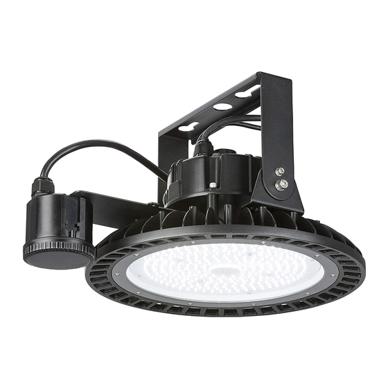
- Page 1 INSTALLATION & MAINTENANCE MANUAL HBN SERIES...
- Page 2 GENERAL INSTRUCTIONS These instructions should be read carefully and retained after installation by the end user for future reference and maintenance. These instructions should be used to aid installation of the following products: HBN150 / HBN200 SAFETY • This product must be installed in accordance with the latest edition of the IEE Wiring Regulations (BS7671) and current Building Regulations.
- Page 3 fitting, screw the mounting hoop into the top of the luminaire (see Fig 1) Screw do mountin Screw down Secure with screw mounting hoop Fig 1 Fig. 1 mounting Bracket mounting • Using the bracket as a template, mark the location of the fixing holes, drill 2 x 10mm holes Using the bracket as a template, mark the location of the fixing holes, drill 2x 10mm ho ensuring not to infringe with any joists, gas/water pipes or electrical cables infringe with any joists, gas or water pipes or electrical cables •...
- Page 4 Tighten expansion bolt nuts but allow enough space for the bracket to mount • Remove the driver housing via the 4 Allen screws (see Fig 3) • Tighten expansion bolt nuts but allow enough space for the bracket to mount • • Tighten expansion bolt nuts but allow enough space for the bracket to mount Remove the driver housing via the 4 Allen screws (see Fig 3) • • Remove the driver housing via the 4 Allen screws (see Fig. 3) Remove the 4 Allen screws Remove the 4 Allen screws Fig. 3 Fig 3 Fig 3 •...
- Page 5 Fig 4 • Position the driver housing over the bracket ensuring all Allen screw holes are correctly aligned and fasten down the 4 Allen screws (see Fig. 5) osition the driver housing into the bracket ensuring all Allen screw holes are correctly aligned and fasten down he 4 Allen screws (see Fig 5) Fasten down Allen screws Fig. 5 Fig 5 g up to the expansion bolts and slide into the bracket (see Fig 6) • Lift the fitting up to the expansion bolts and slide into the bracket (see Fig. 6) Fig.
- Page 6 • Tighten the 2 expansion bolts to secure the luminaire to the surface • Tighten the 2 expansion bolts to secure the luminaire to the surface To wire the luminaire without a dimmer (see fig 7) • Tighten the two expansion bolts to secure the luminaire to the surface • Ensuring correct polarity is observed, carefully wire as shown in Figs. 7-9. Suitable IP rated To wire the luminaire without a dimmer (see fig 7) Earth – green/yellow junction boxes should be used where required Neutral - blue Live - brown Wiring Schemes...
- Page 7 • Line up the sensor bracket with the holes on the luminaire and secure using the 2 screws provided • Attach the sensor to the bracket using the 3 screws provided Ensuring correct polarity is observed, carefully wire as shown in Fig. 1. Suitable IP rated junction •...
- Page 8 GENERAL The light source of this luminaire is not replaceable; when the light source reaches its end of life the whole luminaire should be replaced. Be aware that these products may require an MCB upgrade to a type C due to high inrush currents Clean with a soft dry cloth only, do not use aggressive cleaning products or solvents which may damage the product Do not use any source of high pressure washers to maintain or clean this luminaire...
Need help?
Do you have a question about the HBN Series and is the answer not in the manual?
Questions and answers