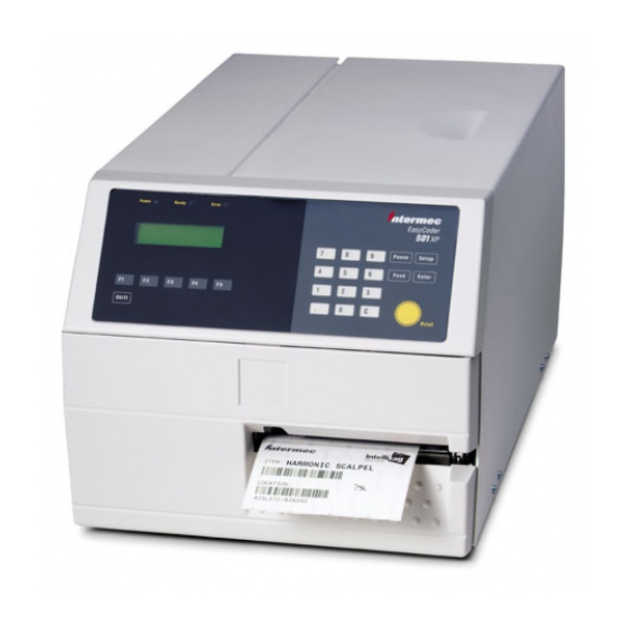
Intermec EasyCoder 501 XP Installation Instructions Manual
Double serial interface board
Hide thumbs
Also See for EasyCoder 501 XP:
- Service manual (210 pages) ,
- User manual (192 pages) ,
- Programmer's reference manual (140 pages)

Related Manuals for Intermec EasyCoder 501 XP


Summary of Contents for Intermec EasyCoder 501 XP
- Page 1 Installation Instructions P/N 1-960472-01 Edition 2 January 2001 EasyCoder XP- & F-Series Double Serial Interface Board...
-
Page 2: Installation Kit
20 mA current loop can be bought separately from Inter- mec. Information in this manual is subject to change without prior notice and does not represent a commitment on the part of Intermec Printer AB. © Copyright Intermec Printer AB, 2001. All rights reserved. Published in Sweden. -
Page 3: Installation
Warning! The electronics compartment contains high voltage com- ponents and wires. Do not open the electronics compart- ment before the printer is safely disconnected from any AC supply. • Open the right-hand door. • Remove the four #T10 Torx screws along the lower edge of the cover over the electronics compartment. -
Page 4: Chapter 2 Installation
fi ts into the two square cut-outs on the left side of the slot. • Attach the Double Serial Interface Board to the printer’s rear plate by means of two of the screws left over when you removed the original cover plate. - Page 5 fi rmly to compress the leaf springs along the front and rear edges of the electronics compartment. • Connect the power cord. • Now you have two new interface connectors on the printer's rear plate in addition to the standard serial interface "uart1:" and the standard parallel interface "centronics:". Connect the interface cables and switch on the power.
- Page 6 AC supply. • Remove the two #T10 Torx screws that hold the interface cover plate on the printer’s rear plate. Remove the cover plate. • Save the cover plate for possible later use. Keep the screws.
- Page 7 • Insert the interface board with the components side facing right, as seen from behind. • Attach the interface board to the printer’s rear plate by means of the two screws left over when you removed the original cover plate.
- Page 8 EasyCoder F2 and F4, cont. EasyCoder XP- & F-Series Double Serial Interface Board – Installation Instructions Ed. 2 • Make sure that the cable between CPU board and interface board runs as illustrated below. CPU Board Interface Board • Put back the cover over the electronics compartment. •...
- Page 9 Chapter 3 Serial Port Confi guration "uart2:" Introduction RS-232 Fit RS-232 circuit on IC2 No circuits on IC3, IC4, or IC18 Strap on S4 deactivated (fi tted on one pin only) Strap on S1 deactivated (fi tted on one pin only) EasyCoder XP- &...
- Page 10 RS-422 Non Isolated No circuit on IC2 Fit RS-422 circuit on IC18 Fit strap on S4 Fit strap on S1 only RS-422 Isolated No circuit on IC2 Fit RS-422 circuit on IC3 Fit strap on S4 Fit strap on S2 only EasyCoder XP- &...
-
Page 11: Connector Confi Gura- Tion
Chapter 3 Serial Port Confi guration "uart2:" RS-485 No circuit on IC2 Fit RS-485 circuit on IC4 Fit strap on S4 if end of cable Fit strap on S3 only Connector Confi gura- tion EasyCoder XP- & F-Series Double Serial Interface Board – Installation Instructions Ed. 2 UART3 RS232: IC11 RS422nonisol.: IC12, S5... - Page 12 Serial Port Confi guration "uart3:" Introduction RS-232 No circuits on IC12, IC13, or IC14 RS-232 circuit fi tted on IC11 Strap on S5/S6 deactivated (fi tted on one pin only) EasyCoder XP- & F-Series Double Serial Interface Board – Installation Instructions Ed. 2 The serial communication port "uart3:"...
-
Page 13: Ma Current Loop
Chapter 4 Serial Port Confi guration "uart3:" RS-422 Non Isolated No circuits on IC13 and IC14 Fit RS-422 circuit on IC12 Remove circuit on IC11 Fit strap on S5 20 mA Current Loop Fit circuits on IC13 and IC14 No circuit on IC12 Remove circuit on IC11 Fit strap on S6 EasyCoder XP- &... - Page 14 - 20 mA current loop + TXD 20 mA current loop - TXD 20 mA current loop + 20 mA current loop (printer active receiver) - 20 mA current loop (printer active receiver) + RS-422 Receive 5 Volt for external use (max. 200 mA)
- Page 15 Notes EasyCoder XP- & F-Series Double Serial Interface Board – Installation Instructions Ed. 2...
Need help?
Do you have a question about the EasyCoder 501 XP and is the answer not in the manual?
Questions and answers