Table of Contents
Advertisement
Quick Links
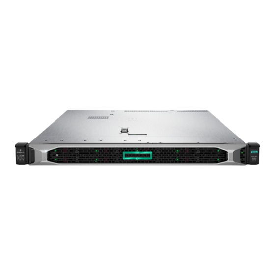
HPE ProLiant DX360 Gen10 Server User Guide
Abstract
This document is for the person who installs, administers, and troubleshoots servers and storage systems. Hewlett
Packard Enterprise assumes you are qualified in the servicing of computer equipment and trained in recognizing hazards
in products with hazardous energy levels.
Part Number: P19004-004
Published: November 2020
Edition: 4
Advertisement
Table of Contents

Related Manuals for HP HPE ProLiant DX360 Gen10


Summary of Contents for HP HPE ProLiant DX360 Gen10
- Page 1 HPE ProLiant DX360 Gen10 Server User Guide Abstract This document is for the person who installs, administers, and troubleshoots servers and storage systems. Hewlett Packard Enterprise assumes you are qualified in the servicing of computer equipment and trained in recognizing hazards in products with hazardous energy levels.
- Page 2 © Copyright 2019 - 2020 Hewlett Packard Enterprise Development LP Notices The information contained herein is subject to change without notice. The only warranties for Hewlett Packard Enterprise products and services are set forth in the express warranty statements accompanying such products and services. Nothing herein should be construed as constituting an additional warranty.
-
Page 3: Table Of Contents
Contents Component identification....................8 Front panel components......................................8 Front panel LEDs and buttons....................................10 UID button functionality..................................12 Front panel LED power fault codes..............................12 Systems Insight Display LEDs....................................12 Systems Insight Display combined LED descriptions..........................14 Rear panel components......................................16 Rear panel LEDs..........................................16 System board components..................................... - Page 4 Temperature requirements................................... 46 Power requirements....................................46 Electrical grounding requirements..............................47 Connecting a DC power cable to a DC power source......................47 Server warnings and cautions....................................48 Rack warnings..........................................49 Identifying the contents of the server shipping carton..........................49 Installing hardware options ....................................50 Installing the server into the rack..................................50 Operating system.........................................
- Page 5 Smart Array controller options..................................105 Installing an HPE Smart Array P408i-a SR Gen10 Controller option............... 105 Installing an HPE Smart Array P408i-p SR Gen10 Controller option............... 109 Installing an HPE Smart Array P816i-a SR Gen10 Controller option............... 112 Installing an HPE Smart Array P824i-p MR Gen10 controller in a configured server........115 Installing the operating system with the HPE Smart Array MR Gen10 P824i-p controller driver..
- Page 6 HPE Insight Cluster Management Utility..............................158 Integrated Management Log....................................159 Intelligent Provisioning......................................159 Intelligent Provisioning operation..............................159 Management security......................................160 Scripting Toolkit for Windows and Linux..............................160 UEFI System Utilities....................................... 161 Selecting the boot mode ..................................161 Secure Boot........................................162 Launching the Embedded UEFI Shell ............................162 HPE Smart Storage Administrator..................................
- Page 7 Regulatory information......................................183 Documentation feedback......................................184 Acronyms and abbreviations..................185...
-
Page 8: Component Identification
Component identification Front panel components 8 SFF Item Description Serial label pull tab Display port (optional) Optical drive (optional) USB 2.0 port (optional) USB 3.0 port iLO Service Port The operating system does not recognize this port as a USB port. SAS/SATA drive bays 4 LFF Item... - Page 9 Item Description iLO Service Port The operating system does not recognize this port as a USB port. USB 3.0 port SAS/SATA drive bays 10 SFF NVMe/SAS Combo Item Description Serial label pull tab Systems Insight Display (optional) USB 3.0 port SAS/SATA/NVMe drive bays When the 10 SFF NVMe/SAS backplane option is installed, NVMe drives must be installed in bays 9 and 10.
-
Page 10: Front Panel Leds And Buttons
Front panel LEDs and buttons 8 SFF/10 SFF Item Description Status UID button/LED Solid blue = Activated Flashing blue: • 1 Hz = Remote management or firmware upgrade in progress • 4 Hz = iLO manual reboot sequence initiated • 8 Hz = iLO manual reboot sequence in progress Off = Deactivated Power On/Standby button and... - Page 11 When all four LEDs described in this table flash simultaneously, a power fault has occurred. Facility power is not present, power cord is not attached, no power supplies are installed, power supply failure has occurred, or the power button cable is disconnected. If the health LED indicates a degraded or critical state, review the system IML or use iLO to review the system health status.
-
Page 12: Uid Button Functionality
Item Description Status Health LED Solid green = Normal. Flashing green = iLO is rebooting. Flashing amber = System degraded. Flashing red = System critical. Power On/Standby button and Solid green = System on. system power LED Flashing green = Performing power on sequence. Solid amber = System in standby. - Page 13 Description Status Processor LEDs Off = Normal Amber = Failed processor DIMM LEDs Off = Normal Amber = Failed DIMM or configuration issue Fan LEDs Off = Normal Amber = Failed fan or missing fan NIC LEDs Off = No link to network Solid green = Network link Flashing green = Network link with activity If power is off, the front panel LED is not active.
-
Page 14: Systems Insight Display Combined Led Descriptions
Description Status Over temp LED Off = Normal Amber = High system temperature detected Amp Status LED Off = AMP modes disabled Solid green = AMP mode enabled Solid amber = Failover Flashing amber = Invalid configuration Power cap LED Off = System is in standby, or no cap is set. - Page 15 Systems Insight Display LED Health LED System power Status and color DIMM (amber) Amber Green DIMM in slot X is in a pre-failure condition. Over temp (amber) Amber Green The Health Driver has detected a cautionary temperature level. Over temp (amber) Amber The server has detected a hardware critical temperature level.
-
Page 16: Rear Panel Components
Rear panel components Item Description Slot 1 PCIe3 Slot 2 PCIe3 Slot 3 PCIe3 (optional - requires second processor) Power supply 2 (PS2) Power supply 1 (PS1) Video port NIC ports (if equipped) iLO Management Port Serial port (optional) USB 3.0 ports FlexibleLOM (optional) Rear panel LEDs Component identification... - Page 17 Item Description Status UID LED Solid blue = Identification is activated. Flashing blue = System is being managed remotely. Off = Identification is deactivated. iLO 5/standard NIC Solid green = Activity exists. activity LED Flashing green = Activity exists. Off = No activity exists. iLO 5/standard NIC Solid green = Link exists.
-
Page 18: System Board Components
System board components Item Description FlexibleLOM connector Primary (processor 1) PCIe riser connector System maintenance switch Front display port/USB 2.0 connector x4 SATA port 1 x4 SATA port 2 x2 SATA port 3 x1 SATA port 4 Front power/USB 3.0 connector Optical/SATA port 5 Energy pack connector microSD card slot... -
Page 19: System Maintenance Switch Descriptions
System maintenance switch descriptions Position Default Function Off = iLO security is enabled. On = iLO security is disabled. Reserved Reserved Reserved Off = Power-on password is enabled. On = Power-on password is disabled. 1, 2, 3 Off = No function On = Restore default manufacturing settings Reserved —... -
Page 20: Dimm Label Identification
DIMM label identification To determine DIMM characteristics, see the label attached to the DIMM. The information in this section helps you to use the label to locate specific information about the DIMM. Item Description Example Capacity 8 GB 16 GB 32 GB 64 GB 128 GB... -
Page 21: Nvdimm Identification
Item Description Example Data width on DRAM x4 = 4-bit x8 = 8-bit x16 = 16-bit Memory generation PC4 = DDR4 Maximum memory speed 2133 MT/s 2400 MT/s 2666 MT/s 2933 MT/s CAS latency P = CAS 15-15-15 T = CAS 17-17-17 U = CAS 20-18-18 V = CAS 19-19-19 (for RDIMM, LRDIMM) V = CAS 22-19-19 (for 3DS TSV LRDIMM) - Page 22 Item Description Definition Capacity 16 GiB Rank 1R (Single rank) Data width per DRAM chip x4 (4 bit) Memory type NN4=DDR4 NVDIMM-N Maximum memory speed 2667 MT/s Speed grade V (latency 19-19-19) DIMM type RDIMM (registered) Other — For more information about NVDIMMs, see the product QuickSpecs on the Hewlett Packard Enterprise website (https:// www.hpe.com/info/qs).
-
Page 23: Nvdimm Led Identification
NVDIMM LED identification Item LED description LED color Power LED Green Function LED Blue NVDIMM-N LED combinations State Definition NVDIMM-N Power LED NVDIMM-N Function LED (green) (blue) AC power is on (12V rail) but the NVM controller is not working or not ready. AC power is on (12V rail) and the NVM controller is ready. -
Page 24: Intel Optane Persistent Memory 100 Series For Hpe Label Identification
State Definition NVDIMM-N Function LED The NVDIMM-N is armed, and the NVDIMM-N is in normal Solid or On operation. The save operation is in progress. Flashing The NVDIMM-N finished saving and battery is still turned on Solid or On (12 V still powered). The NVDIMM-N has an internal error or a firmware update is in Fast-flashing progress. -
Page 25: Processor, Heatsink, And Socket Components
Processor, heatsink, and socket components Item Description Heatsink nuts Processor carrier Pin 1 indicator Heatsink guide/keying feature Alignment post Heatsink keying frame Symbol also on the processor and frame. Device numbers 8 SFF device bay numbering Component identification... - Page 26 8 SFF + 2 SFF device bay numbering Item Description Box 1, bays 1-8 Box 2, bays 1 and 2 4 LFF device bay numbering 10 SFF NVMe/SAS backplane option device bay numbering When the 10 SFF NVMe/SAS backplane option is installed, NVMe drives must be installed in bays 9 and 10.The other bays support a mix of NVMe and SAS drives.
-
Page 27: Hot-Plug Drive Led Definitions
Hot-plug drive LED definitions Item Status Definition Locate Solid blue The drive is being identified by a host application. Flashing blue The drive carrier firmware is being updated or requires an update. Activity ring Rotating green Drive activity. No drive activity. Do not remove Solid white Do not remove the drive. -
Page 28: Smart Carrier Nvme (Scn) Drive Led Definitions
Smart Carrier NVMe (SCN) drive LED definitions The NVMe drive is a PCIe bus device. A device attached to a PCIe bus cannot be removed without allowing the device and bus to complete and cease the signal/traffic flow. CAUTION: Do not remove an NVMe drive from the drive bay while the Do not remove LED is flashing. The Do not remove LED flashes to indicate that the device is still in use. -
Page 29: Uff Drive Components And Leds
Item Status Definition Flashing white The drive ejection request is pending. The drive has been ejected. Power Solid green Do not remove the drive. The drive must be ejected from the PCIe bus prior to removal. Flashing green The drive ejection request is pending. The drive has been ejected. -
Page 30: Hot-Plug Fans
Item Description Status Drive status LED • Off—The drive is not configured by a RAID controller • Solid green—The drive is a member of one or more logical drives • Flashing green (4 Hz)—The drive is operating normally and has activity •... - Page 31 The loss of a single fan rotor (one standard fan) causes loss of redundancy. The loss of two fan rotors (two standard fans or one high performance fan) causes the server to initiate a shutdown. The high performance fans are used for 8 SFF +2 SFF NVMe and 10 SFF drive configurations when NVMe drives are installed in the server.
-
Page 32: Hpe Smart Array P824I-P Mr Gen10 Controller
HPE Smart Array P824i-p MR Gen10 Controller Components Item Description Internal SAS port 1i Internal SAS port 2i Internal SAS port 3i Internal SAS port 4i Controller backup power cable connector Internal SAS port 5i Internal SAS port 6i Component identification... -
Page 33: Hpe Infiniband Hdr/Ethernet 940Qsfp 56X16 Adapter Leds
HPE InfiniBand HDR/Ethernet 940QSFP 56x16 adapter LEDs Link LED status Description A link has not been established. Solid amber Active physical link exists Blinking amber 4 Hz blinking amber indicates a problem with the physical link. Solid green A valid logical (data activity) link exists with no active traffic. - Page 34 Table 1: Ports Item Port Description Management port 1GbE RJ45 Network interface port 10/25G SFP+ based Network interface port 10/25G SFP+ based LEDs The HPE for Pensando DSP DSC-25 2p SFP28 card is a dual-port, single-slot, half-height, half-length (HHHL) SFP28 network adapter.
- Page 35 Item Status Description Flashing green Passing traffic; flashing frequency indicates traffic intensity Solid amber Link fault System status LED System is not powered Solid amber Power is up, software has not booted yet Solid green System is up and fully operational Component identification...
-
Page 36: Operations
Operations Power up the server To power up the server, use one of the following methods: • Press the Power On/Standby button. • Use the virtual power button through iLO. Power down the server Before powering down the server for any upgrade or maintenance procedures, perform a backup of critical server data and programs. -
Page 37: Remove The Server From The Rack
WARNING: To reduce the risk of personal injury, be careful when pressing the server rail-release latches and sliding the server into the rack. The sliding rails could pinch your fingers. 5. After the installation or maintenance procedure, slide the server into the rack: a. -
Page 38: Remove The Hot-Plug Fan
The access panel slides to a closed position. 3. Tighten the security screw on the latch, if needed. Remove the hot-plug fan Procedure 1. Observe the following alert: IMPORTANT: After removing a high-performance (dual-rotor) fan, install or replace the fan within 60 seconds. Otherwise, the server will shut down gracefully. -
Page 39: Remove The Primary Pci Riser Cage
CAUTION: Do not operate the server for long periods with the access panel open or removed. Operating the server in this manner results in improper airflow and improper cooling that can lead to thermal damage. IMPORTANT: For optimum cooling, install fans in all primary fan locations. To replace the component, reverse the removal procedure. -
Page 40: Install The Primary Pci Riser Cage
Install the primary PCI riser cage Procedure 1. Install the PCI riser cage. 2. Install the access panel (Install the access panel). 3. Install the server into the rack (Installing the server into the rack). 4. Connect each power cord to the server. 5. -
Page 41: Remove The Secondary Pci Riser Cage
Remove the secondary PCI riser cage Procedure Observe the following alert: CAUTION: To prevent damage to the server or expansion boards, power down the server and remove all AC power cords before removing or installing the PCI riser cage. Back up all server data. Power down the server (Power down the server). -
Page 42: Install The Secondary Pci Riser Cage
Install the secondary PCI riser cage Procedure 1. Install the PCI riser cage. 2. If needed, install expansion boards (Installing an expansion board in the secondary riser cage). 3. Install the access panel (Install the access panel). 4. Install the server into the rack (Installing the server into the rack). 5. -
Page 43: Remove The 8 Sff Drive Backplane
Remove the 8 SFF drive backplane Procedure 1. Back up all server data. 2. Power down the server (Power down the server). 3. Remove all power: a. Disconnect each power cord from the power source. b. Disconnect each power cord from the server. 4. - Page 44 Operations...
-
Page 45: Setup
Setup Optional service Delivered by experienced, certified engineers, Hewlett Packard Enterprise support services help you keep your servers up and running with support packages tailored specifically for HPE ProLiant systems. Hewlett Packard Enterprise support services let you integrate both hardware and software support into a single package. A number of service level options are available to meet your business and IT needs. -
Page 46: Temperature Requirements
CAUTION: To prevent improper cooling and damage to the equipment, do not block the ventilation openings. When vertical space in the rack is not filled by a server or rack component, the gaps between the components cause changes in airflow through the rack and across the servers. Cover all gaps with blanking panels to maintain proper airflow. CAUTION: Always use blanking panels to fill empty vertical spaces in the rack. -
Page 47: Electrical Grounding Requirements
CAUTION: Protect the server from power fluctuations and temporary interruptions with a regulating uninterruptible power supply. This device protects the hardware from damage caused by power surges and voltage spikes and keeps the system in operation during a power failure. Electrical grounding requirements The server must be grounded properly for proper operation and safety. -
Page 48: Server Warnings And Cautions
CAUTION: If the DC connection exists between the earthed conductor of the DC supply circuit and the earthing conductor at the server equipment, the following conditions must be met: • This equipment must be connected directly to the DC supply system earthing electrode conductor or to a bonding jumper from an earthing terminal bar or bus to which the DC supply system earthing electrode conductor is connected. -
Page 49: Rack Warnings
WARNING: To reduce the risk of fire or burns after removing the energy pack: • Do not disassemble, crush, or puncture the energy pack. • Do not short external contacts. • Do not dispose of the energy pack in fire or water. After power is disconnected, battery voltage might still be present for 1s to 160s. -
Page 50: Installing Hardware Options
The contents of the server shipping carton include: • Server • Power cord • Hardware documentation and software products • Rack-mounting hardware and documentation In addition to the supplied items, you might need: • Operating system or application software • Hardware options •... -
Page 51: Operating System
Operating system This ProLiant server does not ship with provisioning media. Everything required to manage and install the system software and firmware is preloaded on the server. To operate properly, the server must have a supported operating system. Attempting to run an unsupported operating system can cause serious and unpredictable results. -
Page 52: Selecting Boot Options
• To modify the server configuration ROM default settings, press the F9 key in the ProLiant POST screen to enter the UEFI System Utilities screen. By default, the System Utilities menus are in the English language. • If you do not need to modify the server configuration and are ready to install the system software, press the F10 key to access Intelligent Provisioning. -
Page 53: Hardware Options Installation
Hardware options installation Hewlett Packard Enterprise product QuickSpecs For more information about product features, specifications, options, configurations, and compatibility, see the product QuickSpecs on the Hewlett Packard Enterprise website (https://www.hpe.com/info/qs). Introduction Install any hardware options before initializing the server. If multiple options are being installed, read the installation instructions for all the hardware options to identify similar steps and streamline the installation process. -
Page 54: Memory Options
4. Insert the power supply into the power supply bay until it clicks into place. 5. Connect the power cord to the power supply. 6. Route the power cord. Use best practices when routing power cords and other cables. A cable management arm is available to help with routing. -
Page 55: Dimm-Processor Compatibility
DIMM-processor compatibility The installed processor determines the type of DIMM that is supported in the server: • First-generation Intel Xeon Scalable processors support DDR4-2666 DIMMs. • Second-generation Intel Xeon Scalable processors support DDR4-2933 DIMMs. Mixing DIMM types is not supported. Install only the supported DDR4-2666 or DDR4-2933 DIMMs in the server. HPE SmartMemory speed information For more information about memory speed information, see the Hewlett Packard Enterprise website (https:// www.hpe.com/docs/memory-speed-table). -
Page 56: Hpe 16Gb Nvdimm Option
Install the access panel (Install the access panel). Install the server in the rack. Connect each power cord to the server. 10. Connect each power cord to the power source. 11. Power up the server (Power up the server). Use the BIOS/Platform Configuration (RBSU) in the UEFI System Utilities to configure the memory mode. For more information about LEDs and troubleshooting failed DIMMs, see Systems Insight Display combined LED descriptions. - Page 57 • A minimum of one regular DIMM: The system cannot have only NVDIMM-Ns installed. • A supported operating system with persistent memory/NVDIMM drivers. For the latest software information, see the Hewlett Packard Enterprise website (https://persistentmemory.hpe.com). • For minimum firmware versions, see the HPE 16GB NVDIMM User Guide on the Hewlett Packard Enterprise website (https://www.hpe.com/info/nvdimm-docs).
- Page 58 a. Extend the server from the rack (Extend the server from the rack). b. Remove the server from the rack (Remove the server from the rack). Remove the access panel (Remove the access panel). Locate any NVDIMMs already installed in the server. Verify that all LEDs on any installed NVDIMMs are off.
- Page 59 • UEFI System Utilities—Use System Utilities through the Remote Console to configure the server for NVDIMM memory options by pressing the F9 key during POST. For more information about UEFI System Utilities, see the Hewlett Packard Enterprise website (https://www.hpe.com/info/uefi/docs). • iLO RESTful API for HPE iLO 5—For more information about configuring the system for NVDIMMs, see https:// hewlettpackard.github.io/ilo-rest-api-docs/ilo5/.
-
Page 60: Intel Optane Persistent Memory 100 Series For Hpe
◦ Manually back up the NVDIMM-N data before relocating NVDIMM-Ns to another server. ◦ Relocate the NVDIMM-Ns to another server. ◦ Sanitize all NVDIMM-Ns on the new server before using them. Requirements for relocating NVDIMMs or a set of NVDIMMs when the data does not have to be preserved If data on the NVDIMM-N or set of NVDIMM-Ns does not have to be preserved, then •... - Page 61 For more information, see the product QuickSpecs on the Hewlett Packard Enterprise website (https:// www.hpe.com/support/persistentmemoryQS). • HPE DDR4 Standard Memory RDIMMs or LRDIMMs (the number will vary based on your chosen configuration). • Supported firmware and drivers: ◦ System ROM version 1.40 or later ◦...
- Page 62 CAUTION: DIMMs and persistent memory modules are keyed for proper alignment. Align notches on the DIMM or persistent memory module with the corresponding notches in the slot before installing the component. Do not force the DIMM or persistent memory module into the slot. When installed properly, not all DIMMs or persistent memory modules will face in the same direction.
-
Page 63: Installing A High-Performance Fan
11. If removed, reconnect all power cables. 12. Power up the server. 13. Configure the server for Intel Optane persistent memory for HPE. For more information, see Configuring the server for Intel Optane persistent memory 100 series for HPE. Configuring the server for Intel Optane persistent memory 100 series for HPE After installing persistent memory modules, configure the server for Intel Optane persistent memory for HPE. - Page 64 a. Disconnect each power cord from the power source. b. Disconnect each power cord from the server. Do one of the following: a. Extend the server from the rack (Extend the server from the rack). b. Remove the server from the rack (Remove the server from the rack). Remove the access panel (Remove the access panel).
-
Page 65: Drive Options
Install the access panel (Install the access panel). 10. Slide the server into the rack. 11. Connect each power cord to the server. 12. Connect each power cord to the power source. 13. Power up the server (Power up the server). Drive options Depending on the configuration, this server supports SAS, SATA, NVMe, and uFF M.2 drives. -
Page 66: Installing A Hot-Plug Sas Or Sata Drive
Installing a hot-plug SAS or SATA drive Prerequisites Before installing this option, be sure that you have the following: The components included with the hardware option kit Procedure 1. Remove the drive blank. 2. Prepare the drive. 3. Install the drive. Hardware options installation... -
Page 67: Removing A Hot-Plug Sas Or Sata Hard Drive
4. Determine the status of the drive from the drive LED definitions (Hot-plug drive LED definitions). Removing a hot-plug SAS or SATA hard drive CAUTION: For proper cooling, do not operate the server without the access panel, baffles, expansion slot covers, or blanks installed. - Page 68 CAUTION: To prevent improper cooling and thermal damage, do not operate the server unless all bays are populated with either a component or a blank. 2. Remove the drive blank, if installed. 3. Press the Do Not Remove button to open the release handle. 4.
-
Page 69: Removing And Replacing An Nvme Drive
Removing and replacing an NVMe drive An NVMe SSD is a PCIe BUS device. Devices attached to a PCIe bus cannot be removed without allowing the device and the bus to complete and cease signal/traffic flow. Procedure 1. Back up all server data. 2. -
Page 70: Removing And Replacing A Uff Drive
3. Install the drives. Push firmly near the ejection handle until the latching spring engages with the drive bay. 4. Power on the server. To configure the drive, use HPE Smart Storage Administrator. Removing and replacing a uFF drive Procedure 1. -
Page 71: Installing An 8 Sff Optical Drive
To remove the drive carrier: To replace the component, reverse the removal procedure. Installing an 8 SFF optical drive Prerequisites Before installing an optical drive, be sure the 8 SFF display port/USB/optical blank option is installed. For more information, see Installing an 8 SFF display port/USB/optical blank option. Procedure 1. -
Page 72: Universal Media Bay Options
3. Connect the optical drive cable. Universal media bay options Installing a 2 SFF SAS/SATA drive cage Prerequisites Universal media bay options are compatible only with the 8SFF chassis. Hewlett Packard Enterprise recommends installing the P816i-a controller to support 10 SAS/SATA drives. For more information, see Installing an HPE Smart Array P816i-a SR Gen10 Controller option. - Page 73 • The components included with the hardware option kit • T-10 Torx screwdriver Additional cables, as needed. For more information, see SFF cables. • • 2 SFF SAS or SATA drives or blanks For more information, contact a Hewlett Packard Enterprise authorized reseller. Procedure Back up all server data.
- Page 74 Route and connect the data cable. Route and connect the power cable. Hardware options installation...
-
Page 75: Installing A 2 Sff Nvme Drive Cage Option
10. Install the access panel (Install the access panel). 11. Install the server in the rack. 12. Connect each power cord to the server. 13. Connect each power cord to the power source. 14. Power up the server. 15. Install drives. Installing a 2 SFF NVMe drive cage option Prerequisites Before installing this option, be sure that you have the following:... - Page 76 a. Disconnect each power cord from the power source. b. Disconnect each power cord from the server. Do one of the following: a. Extend the server from the rack. b. Remove the server from the rack. Remove the access panel. Use a T-10 Torx screwdriver to remove the universal media bay blank.
- Page 77 10. Use a T-15 Torx screwdriver to install the riser provided in the kit in the primary PCI riser cage. 11. Route and connect the data cable. 12. Install the primary PCI riser cage. 13. Install the access panel (Install the access panel). 14.
-
Page 78: Installing A 2 Sff Hpe Smart Carrier M.2 (Scm) Drive Cage
Installing a 2 SFF HPE Smart Carrier M.2 (SCM) drive cage Prerequisites Hewlett Packard Enterprise recommends installing the P816i-a controller to support more than eight SAS/SATA drives. For more information, see Installing an HPE Smart Array P816i-a SR Gen10 Controller option. Before installing this option, be sure you that have the following: •... - Page 79 Install the drive cage. Route and connect the data cable. Route and connect the power cable. Hardware options installation...
-
Page 80: Installing An 8 Sff Display Port/Usb/Optical Blank Option
10. Install the access panel (Install the access panel). 11. Install the server in the rack. 12. Connect each power cord to the server. 13. Connect each power cord to the power source. 14. Power up the server. 15. Install drives. Installing an 8 SFF display port/USB/optical blank option Prerequisites Before installing this option, be sure that you have the following:... - Page 81 a. Extend the server from the rack (Extend the server from the rack). b. Remove the server from the rack (Remove the server from the rack). Remove the access panel (Remove the access panel). Remove the universal media bay blank. Install the 8 SFF display port/USB/optical blank option.
-
Page 82: Installing The 4 Lff Optical Drive Option
If needed, install an optical drive (Installing an 8 SFF optical drive). 10. Install the access panel (Install the access panel). 11. Install the server in the rack. 12. Connect each power cord to the server. 13. Connect each power cord to the power source. 14. - Page 83 Do one of the following: a. Extend the server from the rack. b. Remove the server from the rack. Remove the access panel. Remove the LFF optical drive bay blank. Install the optical drive. Connect the optical drive cable to the optical drive backplane and to the SATA optical/storage drive connector. Hardware options installation...
-
Page 84: Installing The Rear Drive Riser Cage Option
Install the access panel (Install the access panel). 10. Install the server in the rack. 11. Connect each power cord to the server. 12. Connect each power cord to the power source. 13. Power up the server. Installing the rear drive riser cage option The rear drive riser cage option supports low-profile PCI riser options in slot 2. - Page 85 a. Extend the server from the rack. b. Remove the server from the rack. Remove the access panel. Remove the primary PCI riser cage (Remove the primary PCI riser cage). If installed, remove any expansion boards installed in the riser board. Remove the riser board.
- Page 86 10. Install the drive cage on the riser cage. 11. If needed, install the riser cage bracket on the rear drive riser cage. 12. If needed, install an expansion board (Installing an expansion board in the primary riser cage). 13. Install the rear drive riser cage in the primary riser cage position. Hardware options installation...
-
Page 87: Primary Pci Riser Cage Options
14. Route and connect the data and power cables. Hewlett Packard Enterprise recommends using embedded SATA solutions when connecting the cable. Other options exist. 15. Install drives or blanks (Drive options). 16. Install the access panel (Install the access panel). 17. -
Page 88: Installing An Optional Primary Pci Riser Board
• Slot 1: Full-height, 3/4-length expansion boards (up to 9.5") • Slot 2: ◦ Half-length, half-height expansion boards ◦ 3/4-length expansion boards when either a low-profile type -a controller or no controller is installed. Installing an optional primary PCI riser board Prerequisites Before installing this option, be sure you have the following: •... -
Page 89: Installing The Sata M.2 2280 Riser Option
Install the optional riser board in the riser cage. 10. Install the following, as needed: Expansion boards (Installing an expansion board in the primary riser cage) • GPU (Installing an accelerator or GPU in the primary riser cage) • • Controllers (Smart Array controller options) 11. - Page 90 Procedure Power down the server (Power down the server). Remove all power: a. Disconnect each power cord from the power source. b. Disconnect each power cord from the server. Do one of the following: a. Extend the server from the rack (Extend the server from the rack). b.
-
Page 91: Installing An Expansion Board In The Primary Riser Cage
Remove the screw securing the standoff on the riser. 10. Install the M.2 drives. 11. Install the following, as needed: • Expansion boards (Installing an expansion board in the primary riser cage) Controllers (Smart Array controller options) • 12. Install the primary PCI riser cage (Install the primary PCI riser cage). 13. - Page 92 CAUTION: To prevent damage to electrical components, properly ground the server before beginning any installation procedure. Improper grounding can cause electrostatic discharge. Back up all server data. Power down the server. Remove all power: a. Disconnect each power cord from the power source. b.
-
Page 93: Installing An Accelerator Or Gpu In The Primary Riser Cage
10. Connect any required internal or external cables to the expansion board. 11. Install the primary PCI riser cage. 12. Install the access panel. 13. Install the server in the rack. 14. Connect each power cord to the server. 15. Connect each power cord to the power source. 16. - Page 94 CAUTION: To prevent damage to electrical components, properly ground the server before beginning any installation procedure. Improper grounding can cause electrostatic discharge. Back up all server data. Power down the server. Remove all power: a. Disconnect each power cord from the power source. b.
-
Page 95: Secondary Pci Riser Options
11. Install the primary PCI riser cage. 12. Install the access panel (Install the access panel). 13. Install the server in the rack. 14. Connect each power cord to the server. 15. Connect each power cord to the power source. 16. - Page 96 a. Disconnect each power cord from the power source. b. Disconnect each power cord from the server. Do one of the following: a. Extend the server from the rack (Extend the server from the rack). b. Remove the server from the rack (Remove the server from the rack). Remove the access panel (Remove the access panel).
- Page 97 Use a T-15 Torx screwdriver to remove the riser cage screw. Install the full height PCIe x16 riser cage latch. Use a T-15 Torx screwdriver to remove the riser cage screw. 10. Install the riser cage. Hardware options installation...
-
Page 98: Installing A Secondary Low-Profile Pcie Slot Riser Cage Option
11. Install one of the following, as needed: Expansion boards (Installing an expansion board in the secondary riser cage) • GPU (Installing an accelerator or GPU in the secondary riser cage) • • Controllers (Smart Array controller options) 12. Install the access panel (Install the access panel). 13. - Page 99 CAUTION: To prevent damage to electrical components, properly ground the server before beginning any installation procedure. Improper grounding can cause electrostatic discharge. Back up all server data. Power down the server (Power down the server). Remove all power: a. Disconnect each power cord from the power source. b.
-
Page 100: Installing An Expansion Board In The Secondary Riser Cage
Installing an expansion board in the secondary riser cage Use these instructions to install expansion boards such as Smart I/O cards (such as DSC-25 2-port SFP28 cards), solid state NVMe/PCIe Add-In-Cards, HBAs, CNAs, InfiniBand adapters, and accelerators. Prerequisites Before installing this option, be sure that you have the following: •... - Page 101 • Full-length Hardware options installation...
-
Page 102: Installing An Accelerator Or Gpu In The Secondary Riser Cage
Install the expansion board. 10. Connect any required internal or external cables to the expansion board. 11. Install the access panel (Install the access panel). 12. Install the server in the rack. 13. Connect each power cord to the server. 14. - Page 103 Prerequisites When installing a 3/4-length GPU, a low profile type -a controller must be installed. Before installing this option, do the following: Be sure that the power supplies support the installation of this option. For more information, see the Hewlett Packard •...
- Page 104 Install the secondary full-height PCI riser cage (Installing a secondary full-height PCI riser cage option). Remove the existing rear guide bracket from the card, if installed. 10. If installing a 3/4-length GPU, install the bracket supplied in the kit. A T-15 Torx screwdriver is required to install the bracket. 11.
-
Page 105: Smart Array Controller Options
13. Install the access panel (Install the access panel). 14. Install the server in the rack. 15. Connect each power cord to the server. 16. Connect each power cord to the power source. 17. Power up the server (Power up the server). Smart Array controller options For more information on controllers, see the following information: •... - Page 106 CAUTION: To prevent damage to electrical components, properly ground the server before beginning any installation procedure. Improper grounding can cause electrostatic discharge. Back up all server data. Power down the server. Remove all power: a. Disconnect each power cord from the power source. b.
- Page 107 • 10 SFF SAS/SATA NVMe Combo • 4 LFF Hardware options installation...
- Page 108 IMPORTANT: To enable SmartCache or CacheCade in a P-class type-p Smart Array controller, you must: • Connect the controller backup power cable to the controller backup power connector on the system or riser board. • Connect the energy pack cable to the energy pack connector on the system board. Install the access panel (Install the access panel).
-
Page 109: Installing An Hpe Smart Array P408I-P Sr Gen10 Controller Option
12. Connect each power cord to the power source. 13. Power up the server. Installing an HPE Smart Array P408i-p SR Gen10 Controller option Prerequisites Before installing this option, be sure you that have the following: • The components included with the hardware option kit. •... - Page 110 Use a Torx T-10 screwdriver to install the controller. The controller can also be installed in slot 1. 10. Install the primary PCI riser cage (Install the primary PCI riser cage). 11. Connect the cables. • 8 SFF Hardware options installation...
- Page 111 • 4 LFF IMPORTANT: To enable SmartCache or CacheCade in a P-class type-p Smart Array controller, you must: • Connect the controller backup power cable to the controller backup power connector on the system or riser board. • Connect the energy pack cable to the energy pack connector on the system board. Hardware options installation...
-
Page 112: Installing An Hpe Smart Array P816I-A Sr Gen10 Controller Option
12. Install the access panel (Install the access panel). 13. Install the server in the rack. 14. Connect each power cord to the server. 15. Connect each power cord to the power source. 16. Power up the server. Installing an HPE Smart Array P816i-a SR Gen10 Controller option Prerequisites Before installing this option, be sure that you have the following: •... - Page 113 Remove all power: a. Disconnect each power cord from the power source. b. Disconnect each power cord from the server. Do one of the following: a. Extend the server from the rack. b. Remove the server from the rack. Remove the access panel. Install the controller.
- Page 114 IMPORTANT: To enable SmartCache or CacheCade in a P-class type-p Smart Array controller, you must: • Connect the controller backup power cable to the controller backup power connector on the system or riser board. • Connect the energy pack cable to the energy pack connector on the system board. Install the access panel (Install the access panel).
-
Page 115: Installing An Hpe Smart Array P824I-P Mr Gen10 Controller In A Configured Server
Installing an HPE Smart Array P824i-p MR Gen10 controller in a configured server Procedure Back up data on the system. Close all applications. Update the server firmware if it is not the latest revision. Do one of the following: • If the new Smart Array is the new boot device, install the device drivers. -
Page 116: Installing The Operating System With The Hpe Smart Array Mr Gen10 P824I-P Controller Driver
IMPORTANT: To enable SmartCache or CacheCade in a P-class type-p Smart Array controller, you must: • Connect the controller backup power cable to the controller backup power connector on the system or riser board. • Connect the energy pack cable to the energy pack connector on the system board. 17. -
Page 117: Processor And Heatsink Options
Procedure 1. Power on the server. 2. If you are running the server in UEFI Boot Mode, select F9 (System Utilities). 3. (Optional) If running the server in Legacy Boot Mode, set the controller as the boot controller. 4. (Optional) If running the server in Legacy Boot Mode, change the controller boot order. 5. - Page 118 CAUTION: If installing a processor with a faster speed, update the system ROM before installing the processor. To download firmware and view installation instructions, see the Hewlett Packard Enterprise Support Center website. CAUTION: THE CONTACTS ARE VERY FRAGILE AND EASILY DAMAGED. To avoid damage to the socket or processor, do not touch the contacts.
-
Page 119: Installing A High Performance Heatsink
CAUTION: Be sure to tighten each heatsink nut fully in the order indicated. Otherwise, boot failure or intermittent shutdowns might occur. c. Using a T-30 Torx screwdriver, fully tighten each heatsink nut in the order indicated on the heatsink label (1 -2 -3 -4) until it no longer turns. - Page 120 Hewlett Packard Enterprise recommends using a nonconductive tool. Procedure Observe the following alerts. CAUTION: The processor assembly must be removed and replaced as a unit. Do not remove the processor from the carrier. CAUTION: When handling the heatsink, always hold it along the top and bottom of the fins. Holding it from the sides can damage the fins.
- Page 121 c. Lift the processor heatsink assembly up and away from the system board. d. Turn the processor heatsink assembly over and place it on a work surface with the processor assembly facing up. Release the thermal grease adhesion between the processor assembly and heatsink: a.
- Page 122 The processor remains attached to the carrier. Using an alcohol wipe, remove the existing thermal grease from the processor and heatsink. Allow the alcohol to evaporate before continuing. 10. Remove the plastic cover over the thermal grease on the high performance heatsink. 11.
-
Page 123: Processor, Heatsink, And Socket Components
Processor, heatsink, and socket components Item Description Heatsink nuts Processor carrier Pin 1 indicator Heatsink guide/keying feature Alignment post Heatsink keying frame Symbol also on the processor and frame. Hardware options installation... -
Page 124: Installing The Systems Insight Display Power Module
Installing the Systems Insight Display power module Prerequisites Before installing this option, be sure you have the following: • The components included with the hardware option kit • T-10 Torx screwdriver Procedure Observe the following alerts: WARNING: To reduce the risk of personal injury from hot surfaces, allow the drives and the internal system components to cool before touching them. - Page 125 Using a Torx T-10 screwdriver, remove the Power/UID/USB assembly. • 8 SFF • 4 LFF Hardware options installation...
- Page 126 Guide the SID cable through the front of the server. 10. Install the SID module into the front panel. Using a T-10 Torx screwdriver, secure the module to the chassis with the screws from the kit. • 8 SFF Hardware options installation...
- Page 127 • 4 LFF 11. Connect the SID cables to the front power button/USB 3.0 connector on the system board. Hardware options installation...
-
Page 128: Installing The 4 Lff Display Port/Usb Module
Installing the 4 LFF display port/USB module Prerequisites Before installing this option, be sure you have the following: • The components included with the hardware option kit • T-10 Torx screwdriver Procedure Power down the server (Power down the server). Remove all power: a. - Page 129 Install the 4 LFF display port/USB module. Route and connect the cable. Hardware options installation...
-
Page 130: Installing The Serial Cable Option
Install the access panel (Install the access panel). Install the server in the rack. 10. Connect each power cord to the server. 11. Connect each power cord to the power source. 12. Power up the server (Power up the server). Installing the serial cable option Prerequisites Before installing this option, be sure you have the following:... - Page 131 a. Disconnect each power cord from the power source. b. Disconnect each power cord from the server. Do one of the following: a. Extend the server from the rack (Extend the server from the rack). b. Remove the server from the rack (Remove the server from the rack). Remove the access panel (Remove the access panel).
-
Page 132: Installing The Chassis Intrusion Detection Switch Option
10. Install the server in the rack. 11. Connect each power cord to the server. 12. Connect each power cord to the power source. 13. Power up the server (Power up the server). Installing the Chassis Intrusion Detection switch option Prerequisites Before installing this option, be sure you have the following: •... - Page 133 Assemble the connector/cable harness pin openings to the alignment pegs on the DIMM guard. Install the plastic cover on the DIMM guard. Use a T-15 Torx screwdriver to install the DIMM guard, and then connect the cable to the system board. Install the access panel (Install the access panel).
-
Page 134: Installing The Flexiblelom Option
Installing the FlexibleLOM option Prerequisites Before installing this option, be sure that you have the following: • The components included with the hardware option kit • T-10 Torx screwdriver Procedure Power down the server. Remove all power: a. Disconnect each power cord from the power source. b. -
Page 135: Energy Pack Options
Install the access panel. Slide the server into the rack. Connect the LAN segment cables. 10. Connect each power cord to the server. 11. Connect each power cord to the power source. 12. Power up the server (Power up the server). Energy pack options Hewlett Packard Enterprise offers two centralized backup power source options to back up write cache content on P-class Smart Array controllers in case of an unplanned server power outage. -
Page 136: Hpe Smart Storage Hybrid Capacitor
HPE Smart Array MR controllers 24.23.0-0041 Energy pack option configurations In the HPE ProLiant Dx360 Gen10 Server , an energy pack can be installed in two different orientations, depending on configuration: Installing an energy pack in 8 SFF and 4 LFF configurations •... - Page 137 Installing an energy pack in the 10 SFF SAS/SATA/NVMe Combo backplane configuration Prerequisites The energy pack must be installed in this orientation when the 10 SFF SAS/SATA/NVMe Combo backplane is installed. Procedure Power down the server (Power down the server). Remove all power: a.
- Page 138 Connect the energy pack cable: a. Remove the center fan baffle. b. Connect the energy pack cable to the extender cable. Hardware options installation...
- Page 139 IMPORTANT: To enable SmartCache or CacheCade in a P-class type-p Smart Array controller, you must: • Connect the controller backup power cable to the controller backup power connector on the system or riser board. • Connect the energy pack cable to the energy pack connector on the system board. c.
- Page 140 11. Connect each power cord to the power source. 12. Power up the server. Installing an energy pack in 8 SFF and 4 LFF configurations Prerequisites Before installing this option, be sure you that have the components included with the hardware option kit. Procedure Power down the server (Power down the server).
-
Page 141: Hpe Trusted Platform Module 2.0 Gen10 Option
Install the access panel (Install the access panel). Install the server in the rack. Connect each power cord to the server. Connect each power cord to the power source. 10. Power up the server. HPE Trusted Platform Module 2.0 Gen10 option Overview Use these instructions to install and enable an HPE TPM 2.0 Gen10 Kit in a supported server. -
Page 142: Hpe Trusted Platform Module 2.0 Guidelines
IMPORTANT: In UEFI Boot Mode, the HPE TPM 2.0 Gen10 Kit can be configured to operate as TPM 2.0 (default) or TPM 1.2 on a supported server. In Legacy Boot Mode, the configuration can be changed between TPM 1.2 and TPM 2.0, but only TPM 1.2 operation is supported. - Page 143 WARNING: To reduce the risk of personal injury from hot surfaces, allow the drives and the internal system components to cool before touching them. Update the system ROM. Locate and download the latest ROM version from the Hewlett Packard Enterprise Support Center website. Follow the instructions on the website to update the system ROM.
- Page 144 CAUTION: If the TPM is removed from the original server and powered up on a different server, data stored in the TPM including keys will be erased. CAUTION: The TPM is keyed to install only in the orientation shown. Any attempt to install the TPM in a different orientation might result in damage to the TPM or system board.
- Page 145 Preparing the server for operation Procedure 1. Install any options or cables previously removed to access the TPM connector. 2. Install the access panel. 3. Do one of the following: a. Install the server in the rack, if necessary. b. Install the server in the enclosure. 4.
- Page 146 If the following actions were performed, the server reboots a second time without user input. During this reboot, the TPM setting becomes effective. • Changing from TPM 1.2 and TPM 2.0 • Changing TPM bus from FIFO to CRB • Enabling or disabling TPM •...
-
Page 147: Cabling
Cabling Cabling overview This section provides guidelines that help you make informed decisions about cabling the server and hardware options to optimize performance. CAUTION: When routing cables, always be sure that the cables are not in a position where they can be pinched or crimped. -
Page 148: Sff Backplane To P824I-P Controller
Option kit Cable part number Connects from Connects to 876868-001 1 SFF Rear Backplane P816i-a Smart Array Controller 10 SFF SAS/SATA/NVMe 869675-001 10 SFF backplane, SAS port P408i-a controller Combo backplane 869676-001 10 SFF backplane, ports 1, 2, NVMe riser, ports 1, 2, and 3 and 3 869681-001 10 SFF backplane, port 5... -
Page 149: Sff Backplane To A P408I-A/P816I-A Controller
10 SFF premium backplane to ports 1i/2i in the primary 8 SFF backplane to a P408i-a/P816i-a controller A P408i-a controller is shown, but the routing is the same for the P816i-a. Cabling... -
Page 150: Sff Backplane To P816I-A Controller
2 SFF backplane to P816i-a controller 10 SFF NVMe backplane to NVMe riser Cabling... -
Page 151: Sff Nvme Backplane To Primary Riser
2 SFF NVMe backplane to primary riser 1 SFF rear backplane to system board SATA Cabling... -
Page 152: 10 Sff Backplane To P408I-A Controller
10 SFF backplane to P408i-a controller Additional SFF cabling • 8 SFF backplane to P408i-p controller • 8 SFF backplane to system board SATA • 8 SFF backplane power cable • 2 SFF backplane to P408i-p controller • 2 SFF backplane to system board SATA •... -
Page 153: Lff Backplane To P408I-A Controller
4 LFF backplane to P408i-a controller Additional LFF cabling • 4 LFF backplane to P408i-p controller • 4 LFF backplane to system board SATA Cabling... -
Page 154: Software And Configuration Utilities
Software and configuration utilities Server mode The software and configuration utilities presented in this section operate in online mode, offline mode, or in both modes. Software or configuration utility Server mode Active Health System Online and Offline HPE iLO 5 Online and Offline HPE Smart Storage Administrator Online and Offline... -
Page 155: Active Health System
• Read server configuration information • View Driver/Firmware inventory • Review Event Logs • Respond to Fault Detection Analytics alerts • Open new and update existing support cases Active Health System The Active Health System monitors and records changes in the server hardware and system configuration. The Active Health System provides: •... -
Page 156: Hpe Ilo 5
You can also upload the log to the Active Health System Viewer. For more information, see the Active Health System Viewer documentation at the following website: https://www.hpe.com/support/ahsv-docs. HPE iLO 5 iLO 5 is a remote server management processor embedded on the system boards of supported HPE servers and compute modules. -
Page 157: Ilo Restful Api
◦ iLO RESTful API ◦ Hewlett Packard Enterprise recommends the HPE USB to Ethernet Adapter (part number Q7Y55A). Some servers, such as the XL170r, require an adapter to connect a USB to Ethernet adapter to the iLO Service Port. Hewlett Packard Enterprise recommends the HPE Micro USB to USB Adapter (part number 789904-B21). When you use the iLO Service Port: •... -
Page 158: Hpe Apollo Platform Manager Overview
For more information about iLO Amplifier Pack, see the iLO Amplifier Pack User Guide at the following website: https:// www.hpe.com/support/ilo-ap-ug-en. HPE Apollo Platform Manager overview The HPE Apollo Platform Manager is a rack-level point of contact for HPE ProLiant Scalable System and HPE Apollo administration. -
Page 159: Integrated Management Log
To download the product, go to the Hewlett Packard Enterprise Software Depot (https://www.hpe.com/support/ softwaredepot). Click Insight Management, then click Insight Cluster Management. Integrated Management Log The IML records hundreds of events and stores them in an easy-to-view form. The IML timestamps each event with one- minute granularity. -
Page 160: Management Security
Intelligent Provisioning includes the following components: • Critical boot drivers • Active Health System (AHS) • Erase Utility • Deployment Settings IMPORTANT: • Although your server is preloaded with firmware and drivers, Hewlett Packard Enterprise recommends updating the firmware upon initial setup. Also, downloading and updating the latest version of Intelligent Provisioning ensures the latest supported features are available. -
Page 161: Uefi System Utilities
The STK provides a flexible way to create standard server configuration scripts. These scripts are used to automate many of the manual steps in the server configuration process. This automated server configuration process cuts time from each deployment, making it possible to scale rapid, high-volume server deployments. For more information or to download the STK, see the Hewlett Packard Enterprise website. -
Page 162: Secure Boot
• UEFI Mode (default)—Configures the system to boot to a UEFI compatible operating system. • Legacy BIOS Mode—Configures the system to boot to a traditional operating system in Legacy BIOS compatibility mode. 3. Save your setting. 4. Reboot the server. Secure Boot Secure Boot is a server security feature that is implemented in the BIOS and does not require special hardware. -
Page 163: Hpe Smart Storage Administrator
Prerequisites Embedded UEFI Shell is set to Enabled. Procedure 1. From the System Utilities screen, select Embedded Applications > Embedded UEFI Shell. The Embedded UEFI Shell screen appears. 2. Press any key to acknowledge that you are physically present. This step ensures that certain features, such as disabling Secure Boot or managing the Secure Boot certificates using third-party UEFI tools, are not restricted. -
Page 164: Hpe Mr Storage Administrator
HPE MR Storage Administrator HPE MR Storage Administrator is a web-based application that enables you to monitor, configure, maintain, and troubleshoot the HPE Smart Array MR controller. MR Storage Administrator enables you to view, create, and manage storage configurations. IMPORTANT: The HPE MR Storage Administrator manages only the HPE Smart Array MR controllers. It does not manage HPE Smart Array SR controllers. -
Page 165: Storcli
StorCLI The Storage Command Line Interface (StorCLI) tool is the command line management software designed for the HPE Smart Array MR controller. StorCLI is a command line interface that is designed to be easy to use, consistent, and easy to script. - Page 166 Service Pack for ProLiant SPP is a systems software and firmware solution delivered as a single ISO file download. This solution uses SUM as the deployment tool and is tested and supports HPE ProLiant, HPE BladeSystem, HPE Synergy, and HPE Apollo servers and infrastructure.
- Page 167 • SPP: A comprehensive systems software and firmware update solution, which is delivered as a single ISO image. SUM: A tool for firmware and driver maintenance for HPE ProLiant servers and associated options. • NOTE: SUM and iLO Amplifier Pack should not manage the same nodes. Updating firmware from the System Utilities Use the Firmware Updates option to update firmware components in the system, including the system BIOS, NICs, and storage cards.
-
Page 168: Drivers
8. Flash the system ROM by entering fwupdate –d BIOS -f filename. 9. Reboot the server. A reboot is required after the firmware update in order for the updates to take effect and for hardware stability to be maintained. Online Flash components This component provides updated system firmware that can be installed directly on supported operating systems. -
Page 169: Proactive Notifications
• Private or hybrid cloud computing • Big data and mobility requirements • Improving data center infrastructure • Better use of server, storage, and networking technology For more information, see the Hewlett Packard Enterprise website: https://www.hpe.com/services/consulting Proactive notifications 30 to 60 days in advance, Hewlett Packard Enterprise sends notifications to subscribed customers on upcoming: •... -
Page 170: Troubleshooting
Troubleshooting Troubleshooting resources Troubleshooting resources are available for HPE Gen10 and Gen10 Plus server products in the following documents: • Troubleshooting Guide for HPE ProLiant Gen10 and Gen10 Plus servers provides procedures for resolving common problems and comprehensive courses of action for fault isolation and identification, issue resolution, and software maintenance. -
Page 171: Removing And Replacing The System Battery
Removing and replacing the system battery The system battery provides power to the real-time clock. If the server no longer automatically displays the correct date and time, you might need to replace the system battery. WARNING: The computer contains an internal lithium manganese dioxide, a vanadium pentoxide, or an alkaline battery pack. - Page 172 7. To replace the component, reverse the removal procedure. 8. Properly dispose of the old battery. For more information about battery replacement or proper disposal, contact an authorized reseller or an authorized service provider. Removing and replacing the system battery...
-
Page 173: Specifications
Specifications Environmental specifications Specification Value Temperature range — Operating 10°C to 35°C (50°F to 95°F) Nonoperating -30°C to 60°C (-22°F to 140°F) Relative humidity (noncondensing) — Operating Minimum to be the higher (more moisture) of -12°C (10.4°F) dew point or 8% relative humidity Maximum to be 24°C (75.2°F) dew point or 90% relative humidity Nonoperating... -
Page 174: Power Supply Specifications
Specification Value 13.04 kg (28.74 lb) SFF minimum (one drive, one processor, one power supply, two heatsinks, one Smart Array controller, five fans) 16.27 kg (35.86 lb) SFF maximum (10 drives, two processors, two power supplies, two heatsinks, one Smart Array controller, seven fans) 13.77 kg (30.36 lb) LFF minimum (one drive, one... -
Page 175: Hpe 800W Flex Slot Platinum Hot-Plug Low Halogen Power Supply
Specification Value Rated input frequency 50 Hz to 60 Hz Not applicable to 240 VDC Rated input current 5.6 A at 100 VAC 2.7 A at 200 VAC 2.3 A at 240 VDC for China only Maximum rated input power 557 W at 100 VAC 539 W at 200 VAC 537 W at 240 VDC for China only... -
Page 176: Hpe 800W Flex Slot Titanium Hot-Plug Low Halogen Power Supply
Specification Value Rated input current 9.1 A at 100 VAC 4.4 A at 200 VAC 3.6 A at 240 VDC for China only Maximum rated input power 899 W at 100 VAC 867 W at 200 VAC 864 W at 240 VDC for China only BTUs per hour 3067 at 100 VAC 2958 at 200 VAC... -
Page 177: Hpe 800W Flex Slot Universal Hot-Plug Low Halogen Power Supply
Specification Value Maximum rated input power 851 W at 200 VAC 848 W at 240 VAC 848 W at 240 VDC for China only BTUs per hour 2905 at 200 VAC 2893 at 240 VAC 2893 at 240 VDC for China only Power supply output —... -
Page 178: Hpe 800W Flex Slot -48Vdc Hot-Plug Low Halogen Power Supply
Specification Value BTUs per hour 2964 at 200 VAC 2951 at 230 VAC 2936 at 277 VAC 2943 at 380 VDC Power supply output — Rated steady-state power 800 W at 200 VAC to 277 VAC input Maximum peak power 800 W at 200 VAC to 277 VAC input HPE 800W Flex Slot -48VDC Hot-plug Low Halogen Power Supply Specification... -
Page 179: Hpe 1600 W Flex Slot Platinum Hot-Plug Low Halogen Power Supply
WARNING: To reduce the risk of electric shock or energy hazards: • This equipment must be installed by trained service personnel. • Connect the equipment to a reliably grounded secondary circuit source. A secondary circuit has no direct connection to a primary circuit and derives its power from a transformer, converter, or equivalent isolation device. -
Page 180: Hot-Plug Power Supply Calculations
Specification Value Rated steady-state power 1600 W at 200 VAC to 240 VAC input 1600 W at 240 VDC input Maximum peak power 2200 W for 1 ms (turbo mode) at 200 VAC to 240 VAC input Hot-plug power supply calculations For hot-plug power supply specifications and calculators to determine electrical and heat loading for the server, see the Hewlett Packard Enterprise Power Advisor website (https://www.hpe.com/info/poweradvisor/online). -
Page 181: Websites
Websites General websites Hewlett Packard Enterprise Information Library https://www.hpe.com/info/EIL Single Point of Connectivity Knowledge (SPOCK) Storage compatibility matrix https://www.hpe.com/storage/spock Storage white papers and analyst reports https://www.hpe.com/storage/whitepapers For additional websites, see Support and other resources. Websites... -
Page 182: Support And Other Resources
Support and other resources Accessing Hewlett Packard Enterprise Support • For live assistance, go to the Contact Hewlett Packard Enterprise Worldwide website: https://www.hpe.com/info/assistance • To access documentation and support services, go to the Hewlett Packard Enterprise Support Center website: https://www.hpe.com/support/hpesc Information to collect •... -
Page 183: Remote Support
IMPORTANT: Access to some updates might require product entitlement when accessed through the Hewlett Packard Enterprise Support Center. You must have an HPE Passport set up with relevant entitlements. Remote support Remote support is available with supported devices as part of your warranty or contractual support agreement. It provides intelligent event diagnosis, and automatic, secure submission of hardware event notifications to Hewlett Packard Enterprise, which will initiate a fast and accurate resolution based on your product's service level. - Page 184 Additional regulatory information Hewlett Packard Enterprise is committed to providing our customers with information about the chemical substances in our products as needed to comply with legal requirements such as REACH (Regulation EC No 1907/2006 of the European Parliament and the Council). A chemical information report for this product can be found at: https://www.hpe.com/info/reach For Hewlett Packard Enterprise product environmental and safety information and compliance data, including RoHS and REACH, see:...
- Page 185 Canadian Standards Association Customer Self Repair FSBBU Flex slot battery backup graphics processing unit host bus adapter HP SUM HP Software Update Manager HPE PMM HPE Persistent Memory module HPE SSA HPE Smart Storage Administrator International Electrotechnical Commission Integrated Lights-Out...
- Page 186 Integrated Management Log International Organization for Standardization JSON JavaScript Object Notation large form factor LRDIMM load reduced dual in-line memory module NAND Not AND nonmaskable interrupt NVRAM nonvolatile memory PCIe Peripheral Component Interconnect Express power distribution unit POST Power-On Self-Test RBSU ROM-Based Setup Utility RDIMM...
- Page 187 small form factor Systems Insight Display Systems Insight Manager Service Pack for ProLiant TMRA recommended ambient operating temperature Trusted Platform Module UDIMM unregistered dual in-line memory module UEFI Unified Extensible Firmware Interface unit identification universal serial bus Virtual Connect Version Control Agent VCRM Version Control Repository Manager voltage direct-current...
Need help?
Do you have a question about the HPE ProLiant DX360 Gen10 and is the answer not in the manual?
Questions and answers