
Related Manuals for Intermec 5900 SERIES


Summary of Contents for Intermec 5900 SERIES
- Page 1 5900 SERIES Mobile Mount Radio Data Terminal USER’S GUIDE " " " " " " " " " " " " " " " " " " " " " " " " " " " " PN: 961-047-121 Revision A...
- Page 2 Send your comments to: Publications Department Intermec Technologies Corporation 550 Second Street SE Cedar Rapids, IA 52401 Telephone (319) 369-3100 Faxsimile (319) 369-3453 ä...
-
Page 3: Table Of Contents
" " " " " " " " " " " SECTION 1 User Information About this Manual Section One Section Two Section Three General Information Installation Keyboard ..........How it Works The Terminal . - Page 4 CONTENTS " Power Cable Assembly Assembling the In-line Fuse Holder Terminating Wire Ends Side Mount Battery Connection Power Cable Connection Top Mount Battery Connection Secure the Power Cable Mounting the Terminal Connections to the Terminal ON/OFF button Desktop Installation Kit Instructions Kit Description Instructions .
- Page 5 Scan Options ........Scan Options [1] .
- Page 6 CONTENTS " Main Menu ..........Version Info Main Menu .
-
Page 7: User Information
" " " " " " " " " " About this Manual This User’s Guide contains a product introduction and General Information (Section One ), Installation Instructions (Section Two), and User Interface information (Section Three). Section One The General Information section is most useful to the end user. It describes the ON/OFF switch, cable connections, the display, and the keyboard. -
Page 8: General Information
SECTION 1 General Information " General Information The Mobile Mount Radio Data Terminal is a powerful real-time data collec- tion computer for warehouse and automated material handling environ- ments. The computer electronics, radio module, power converter, keyboard, and the large display are all housed within a single metal container that is designed to meet NEMA-3 standards. -
Page 9: The Terminal
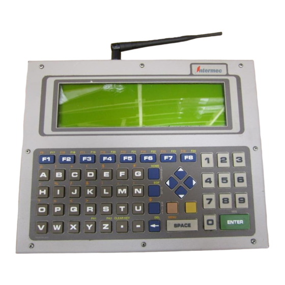
The Terminal The illustrations in Figure 1-1 and Figure 1-2 will familiarize you with the external features of the Mobile Mount Radio Data Terminal. Each work day you should check to make sure that: The antenna connector is secure. " All mounting knobs are tight. -
Page 10: The Display
SECTION 1 General Information " On/Off Switch This is a push-push type switch located on the rear of the unit next to the power connector. Press the switch once to turn the unit ON. Press the switch a second time to turn the unit OFF. When the unit is turned ON, the backlight comes on and a message appears on the display. -
Page 11: Status Indicators
Status Indicators The display also shows a group of status indicators (icons). Their location on the display can be changed through the User Interface menus. These status indicators tell you: cursor location by row and column number: " 01,02 = row 1, column 2 whether transmitting or receiving: "... -
Page 12: Miscellaneous Keys
SECTION 1 General Information " Miscellaneous Keys The key with the left-pointing arrow serves as a nates one character to the left each time you press it. Use the key to produce uppercase letters. SHIFT The two keys above the key, and to the right of each key. -
Page 13: Maintenance
Maintenance Your terminal requires very little maintenance. Clean the terminal and the display periodically, and perform the daily checks listed below. If a failure message appears on the display, the Radio Data Terminal may need to be sent to an authorized service facility for repair or adjustment. Contact your authorized service representative for further instructions. -
Page 14: Factory Service
SECTION 1 General Information " Factory Service When products must be shipped for repair: Package in original shipping carton if possible. " Fill out a Product Service Information Card and include this card " with the product. If the original shipping container is not available, appropriate packaging materials can be substituted. -
Page 15: Table 1-1 Specifications
Physical Size: 2.4 inches X 8.9 inces active area (display) (6.0 cm. X 22.5 c. h x w) 12.5 inches X 10.0 inches X 3.0 inches (enclosure)* (31.75 cm X 25.4 cm X 7.62 cm 1,w,d) *add 3.25 inches (8.25 cm) for antenna Weight: 13.75 pounds (6.24 kilograms) with bracket Keyboard:... - Page 16 SECTION 1 General Information " Specifications (continued) Power output: 2.0 watts, frequency modulated (FM) Frequency range: UHF Private Land Mobile Radio Service (crystal-controlled on assigned frequency) Receiver sensitivity: -90 dBm RF communication speed: 4800/9600 bps. 1-10 RT5900 SERIES Mobile Mount Radio Data Terminal...
-
Page 17: Installation Instructions
" " " " " " " " " " Quantity 2 each 2 each 4 each 4 each 4 each 4 each 8 each 8 each Installation Instructions " " " " " " " " " " Table 2-1 Parts List kit NPN: 203-300-005 Description... -
Page 18: Tools Required For Installation
SECTION 2 Installation Instructions " Tools Required for Installation Wire crimping and stripping tool. An electric drill, #26 drill bit. Common hand tools. 2-2 RT5900 SERIES Mobile Mount Radio Data Terminal 1. Fuse holder 2. Fuse (15 amp, 250 volt) 3. -
Page 19: Introduction
SECTION 2 Installation Instructions " Introduction The Mobile Mount Radio Data Terminal can be mounted on motorized load-handling equipment such as a forklift. During this installation the power cable is wired directly to the vehicle battery or bank of batteries. This direct connection takes advantage of the filtering and regulation capa- bilities of storage batteries. -
Page 20: Power Cable Routing
SECTION 2 Installation Instructions " Power Cable Routing Decide where you will mount the bracket for the Mobile Mount Radio Data Terminal, then proceed with the instructions below. Completely install the power cable before connecting the unit. Begin installation by routing the cable from the general area where the terminal will be mounted. -
Page 21: Power Cable Assembly
Power Cable Assembly The power cable must have an in-line fuse installed before making final connections to the vehicle battery. You must also crimp the 3/8 inch termi- nal rings to the wire ends. Assembling the In-line Fuse Holder The in-line fuse holder consists of a rubber boot, two crimp-type fuse clips, and a 15 amp fuse. -
Page 22: Figure 2-3 Assembling The In- Line Fuse Holder
SECTION 2 Installation Instructions " 2-6 RT5900 SERIES Mobile Mount Radio Data Terminal 1. Fuse clips 2. Red wire (6- -7 inches) 3. Fuse holder ”boot” 4. Red wire 5. Gray power cable 6. Brown (or Black) wire Figure 2-3 Assembling the In- Line Fuse Holder... -
Page 23: Terminating Wire Ends
SECTION 2 Terminating Wire Ends Crimp 3/8-inch terminal rings to the stripped end of the brown wire and to the red wire from the fuse holder. See the battery drawing and instructions for recommended assembly to connect the cable to the vehicle battery. Strip approximately 1/4”... -
Page 24: Side Mount Battery Connection
SECTION 2 Installation Instructions " Side Mount Battery Connection Remove both battery cable retaining screws from the vehicle battery. Screw a 3/8” nut as far as it will go onto a 3/8” x 1-1/2” bolt. Slip a 3/8” flat washer onto the bolt. Slide the positive (red wire) terminal ring of the cable onto the bolt. -
Page 25: Power Cable Connection
SECTION 2 Power Cable Connection 1. 3/8” nut 2. Vehicle battery 3. Vehicle battery cable 4. Fuse link 5. 3/8” X 1-1/2” bolt 6. 3/8” washers Figure 2-6 Top Mount Battery Top Mount Battery Connection Connect the positive (red wire) terminal ring from the power cable to the positive battery terminal, as shown, using a 3/8”... -
Page 26: Mounting The Terminal
SECTION 2 Installation Instructions " Mounting the Terminal The mounting kit consists of a pre-drilled mounting bracket, four mounting knobs, and four lock washers. Use at least two sets of 3/8” bolts, nuts, flat washers and lock washers to install the mounting bracket. Since installa- tions can vary and may require different bolt lengths, that hardware is not furnished in this kit and must be purchased locally. -
Page 27: Connections To The Terminal
SECTION 2 1. 15-pin connector (communication) 2. Power connector 3. On/Off switch 4. 9-pin connector (scanner) Figure 2-8 Cable Connections Connections to the Terminal Connect cables as shown in Figure 2-8. Simply align each cable connector to the appropriate connector on the terminal and push them together. In addition, you must turn the power cable connector clockwise to lock it in place. -
Page 28: Desktop Installation Kit Instructions
SECTION 2 Installation Instructions " Desktop Installation Kit Instructions Quantity Kit Description This kit contains a power supply, power cables, and mechanical hardware to permit desktop (nonvehicular) operation of the Mobile Mount Radio Data Terminal. The power cable furnished in this kit has the correct connector on one end to fit the terminal;... -
Page 29: Connect The Dc Power Cable
Instructions Mounting Bracket Experiment with the terminal and the mounting bracket to determine the bracket arrangement that will provide you with the best viewing angle. Use two knobs and two lock washers on each side to attach the bracket to the terminal. -
Page 30: Figure 2-9 The Nc4000 Power Supply
SECTION 2 Installation Instructions " AC POWER CONNECTOR (CABLE TO WALL OUTLET) DC POWER CONNECTOR (USE CABLE #216-860- -001) Figure 2-9 The NC4000 Power Supply 2-14 RT5900 SERIES Mobile Mount Radio Data Terminal... -
Page 31: User Interface Instructions
" " " " " " " " " " Introduction The user interface for the Mobile Mount Radio Data Terminal consists of the keyboard, the display, and the operating system (program) that allows you to customize the unit operation. The first section of this manual has already described the keyboard and the display;... -
Page 32: The Keyboard
SECTION 3 User Interface Instructions " The Keyboard Accessing the Menu Press the LEFT SHIFT and then the MENU Main Menu. ENTER Key Press this key to go to the next whole (parent) menu. Multiple presses of this key cause the program to act as a loop, taking you back, eventually, to the starting point. -
Page 33: Right Shift/Space
SECTION 3 Right Shift/Space Press the RIGHT SHIFT key and then the SPACE key to change the size of displayed text from large to small, or vice- -versa. MENU SPACE 1. Arrow Keys 2. Right Shift 3. Left Shift 4. Alpha Shift SHIFT key Use this key to shift the alpha keys between upper and lower case. -
Page 34: Main Menu
SECTION 3 User Interface Instructions " Main Menu Press the LEFT SHIFT and then the MENU main menu. The main menu appears on the display. You can then enter a number (1 thru 7) to make a selection. Making a selection of 2, 3, 4, 5, or 7 will cause that menu to display. -
Page 35: Main Menu 2
SECTION 3 Main Menu Set- -up Parms LCD Parms Beeper Setup Tests Version Info Exit Menus More Enter Password Beeper Setup Keyclick Error Tone Set- -up Parms Radio # Barcode Parms Protocol Opts Display Opts Radio Comm Cold Start Tests LCD Parms Peripherals LCD Contrast... -
Page 36: Set Parameters
SECTION 3 User Interface Instructions " Main Menu Set Parameters This menu is password protected to prevent unauthorized changes to the way the terminal operates, or to prevent loss of data. You can change the following parameters for the current (foreground) session only: the number that designates this radio "... - Page 37 Radio # Enter Unit Number: Press A for Advanced Setup Scanner Type No Scanner Wand Laser Wand Emulate Protocol Opts Host View Size Data Stream Extended Cmds 5250 3270 VT220 Native " NOTE: Parameter settings you make only apply to the current session. If more than one session is available to you, use the Session Menu (#4 in Main Menu 2) to verify or change the current session before making parameter settings.
-
Page 38: Advanced Setup (Radio #)
SECTION 3 User Interface Instructions " Advanced Setup (Radio #) This sub menu can be used to define parameters for communicating in a multiple host environment. In the “Advanced Setup” menu (SST and OWL only), you designate the session to be modified in the following menus. Note that all of the menu functions shown may not actually be available to you: this depends upon whether or not multiple hosts exist, and whether or not different data streams are supported. -
Page 39: Host A
" NOTE: Selections in these menus apply only to the current session. Use the Session Menu to verify or change the current session. Radio # Enter Unit Number: Press A for Advanced Setup Advanced Setup Advanced Setup Radio Config# ENTER Advanced Setup 1) Host A 2) Host B... -
Page 40: Barcode Parms (Continued)
SECTION 3 User Interface Instructions " Barcode Parms (continued) The Barcode Parms flowchart shows four screens (e.g., Scanner Type, Scan Options, Scan Options [1], Scan Options [2], plus their option menus). You must press the ENTER key to pass from Scanner Type to Scan options, and again to pass from one scan options menu to the next. -
Page 41: Scanner Type
SECTION 3 User Interface Instructions " Barcode Parms Scanner Type No Scanner Wand Laser Specify scanner time- Wand Emulate Auto Detect out period. Range is 1- -200 seconds. Scan Options Scan Timeout Seconds Redundancy MOD 10 Chk Concatenate BC Type Char Stream Scan Scan All Flds Scan Timeout... -
Page 42: Scan Options [1]
SECTION 3 User Interface Instructions " Scan Options [1] Designates the bar codes to be recognized by the terminal. When you select a bar code type, an option menu (see Scan Options [1] ) displays to further define your choice. If you will not be selecting a bar code type within the Scan Options [1] menu, press the ENTER key to go directly to the Scan Options [2] menu. - Page 43 SECTION 3 User Interface Instructions " Code 128 Enabled Enabled Add- -on 2 UCC/EAN Add- -on 5 Sys 1 UPCE Sys 2 UPCE Expand E to A Codabar Codabar ABC codabar Enabled Add- - on 2 Add- - on 5 Expand 8to13 Code 39 Enabled...
-
Page 44: Other Scan Options [1] & [2
SECTION 3 User Interface Instructions " Other Scan Options [1] & [2] After making your selection from the scan options menus, an options menu for the chosen bar code type displays. Press the corresponding number(s) to highlight your choice(s) and make the selection(s). Then, press the ENTER key to display the Lengths menu, where you can select minimum and maximum bar code lengths. - Page 45 SECTION 3 BARCODE LENGTH ME- XXXXXXX Max Length:XX XXXXXXX Max Length:XX Screens below allow you to drop Min Length: XX up to 15 leading or trailing char- acters from the bar code. Typi- cally used to remove check digits or non-significant zeros. XXXXXXX Max Length:XX Min Length: XX...
-
Page 46: Protocol Options
SECTION 3 User Interface Instructions " Protocol Options Host View Size The default value for display width is shown. This option tells the terminal that the host computer sends information in a different size or format. When the width line is highlighted, you can enter a number, 1 thru 80, to change the width of the display. - Page 47 SECTION 3 " Protocol Opts Host View Sze Data Stream Extended Cmds 5250 3270 VT220 Native Host View Size Width Default shown Enter 1- -80 to change width Default is enabled. When enabled, pressing <F1> is equivalent to pressing Gold Data Stream (“right shift”) 0, while pressing Native...
-
Page 48: Display Options
SECTION 3 User Interface Instructions " Display Options Cursor Mode Specify the cursor style (on the display) that you prefer. The display shows an icon of the selected cursor style. Select one of the following: Underline Blink Block Blink Underline Block Cursor Cold Start (not shown) You can perform a cold start from this menu. -
Page 49: Protocol
SECTION 3 Protocol This allows you to choose the communication protocol that the terminal must use to communicate to the host computer. Choices are: " SST Diag Mode " Baud Rate In this submenu you will specify the communication speed (rate) at which the terminal talks to the host computer: Choices are: 4800... -
Page 50: Main Menu
SECTION 3 User Interface Instructions " Main Menu LCD Parms You can adjust the liquid crystal display (LCD) by: changing the contrast " changing the screen size " relocating the cursor (Screen Mode) " Contrast Use the Up and Down arrow keys to adjust the contrast on the display. Select Size Use the Up and Down arrow keys to adjust the screen size. - Page 51 LCD Contrast User cursor UP and DOWN keys to adjust Screen Size: Screen Mode Center Cursor Corner Mode Page Mode Lazy Mode ”Lazy Mode” repositions text only as needed to keep cursor in view. " NOTE: In the Screen Size (#2) menu above, ON indicates 40 columns by 12 lines is selected.
-
Page 52: Display Annunciators
SECTION 3 User Interface Instructions " Display Annunciators Annunciators show the radio terminal’s current status or operation in prog- ress. The following lists some of the annunciators common to all emula- tions. Low Battery Annunciator: When the low battery annunciator appears, you may want to connect the battery pack to a charger as soon as possible. - Page 53 SECTION 3 Again, these are just a few of the display annunciators that are common to all emulations. There are others, specific to individual emulations, that are not shown here. Annunciator bibliography (emulation/reference source/Norand Part Num- ber) VT220 emulation: VT220/ANSI Terminal Emulation Programmer’s "...
-
Page 54: Main Menu
SECTION 3 User Interface Instructions " Main Menu Beeper Setup This menu allows you to adjust the volume and the length (duration) of the tone for the audible key click indicator or for the error tone. Volume is ad- justable in steps, from 0- -32, while Length is adjustable in steps from 0- -10. You can select either (1) Key Click or (2) Error Tone from this menu. - Page 55 SECTION 3 " Beeper Setup KeyClick Error Tone KeyClick Volume Length Volume User cursor UP and User cursor UP and DOWN keys to adjust. DOWN keys to adjust. Keyclick > 5 Keyclick > 3 (or Error Tone > 5) (or Error Tone > 3) Range = 0-32 Range = 0-10 Default = 5...
-
Page 56: Main Menu
SECTION 3 User Interface Instructions " Main Menu Tests Tests menu has five choices that you select by entering the appropriate num- ber: (1) Peripherals, (2) Converters, (3) Memory View (4) Packet Driver, or (5) Numbers. Peripherals (see Peripherals menu) You can test the following from within this menu: Radio "... - Page 57 SECTION 3 Tests Peripherals Converters Memory View Packet Driver Numbers Peripherals Radio Test RS232 Test Display Test Keyboard Test Scanner Test Radio Test requires a unique password. Converters A to D D to A RSSI Test RSSI stands for Received Signal Strength Indicator Memory View - - Exit...
-
Page 58: Peripherals Menu
SECTION 3 User Interface Instructions " Peripherals Menu Radio Tests The Radio test is used for calibration purposes and is password-protected by a unique seven-digit password before the menu will display. Technicians and engineers may use these tests to determine the performance of the radio transceiver at different communication speeds and modes of operation. - Page 59 SECTION 3 " Enter unique 7- -digit password. Radio Tests Random Send Alt Send Receive Center Freq. This will be the name of which- ever Radio Test is in progress. Random Send BAUD RATE: 4800 You must enter the baud rate (4800 or 9600) for each test.
-
Page 60: Main Menu
SECTION 3 User Interface Instructions " Main Menu Version Info This choice from the main menu tells you the version (expressed in an al- pha-numeric code) of the firmware stored within your radio data terminal. The date that firmware was released, and the identification number of the terminal are also displayed. -
Page 61: Main Menu
" NOTE: The Cloning Option described below is NOT ENABLED on 5900 SERIES terminals. Cloning Opts This function allows you to “clone” (copy) either an application program or parameter settings from one terminal (the “source” terminal) to another (the “target”... - Page 62 SECTION 3 User Interface Instructions " To clone parameters from one terminal to another: Make sure the desired parameters are already set and saved in the source terminal. Connect terminals together via the cloning cable. With both terminals ON, access the Cloning Opts menu. On the source terminal, select menu item #2, “Clone Parms.”...
-
Page 63: Session Menu
SECTION 3 Session Menu The Session Menu allows you to define different host communication ses- sions and to designate a “hot key” that allows switching quickly between different sessions. When you select Set Hot Key, the current hot key is dis- played. - Page 64 SECTION 3 User Interface Instructions " 3-34 RT5900 SERIES Mobile Mount Radio Data Terminal...
Need help?
Do you have a question about the 5900 SERIES and is the answer not in the manual?
Questions and answers