
Related Manuals for Intermec 1100 Series


Summary of Contents for Intermec 1100 Series
- Page 1 1100 Series Data Terminal USER’S GUIDE " " " " " " " " " " " " " " " " " " " " " " " " " " " " PN: 961-047-069 Revision B September 1998...
- Page 2 " NOTICE The information contained herein is proprietary and is provided solely for the purpose of allowing customers to operate and service Intermec manufactured equipment and is not to be released, reproduced, or used for any other purpose without written permission of Intermec.
- Page 3 NOTICE FCC rules section 15.203 and Canada’s RSS-210 require that this device be oper- ated using an antenna furnished by Intermec Technologies Corporation. The an- tenna coupling on this product has been designed to accept only antennas manufactured by us. Use of an antenna other than that furnished with the equip- ment is prohibited by FCC and Industry Canada rules.
- Page 4 à proximité de la fuite. CAUTION: Intermec Technologies Corporation suggests you buy cables from us to connect with other devices. Our cables are safe, meet FCC rules, and suit our products. Other cables may not be tested. They may cause problems from electrostatic discharge or induced energy.
- Page 5 Intermec Technologies Corporation recommends that you only purchase Norand Mobile Systems Division certified modems. Intermec does not certify all modems available in the marketplace. Intermec does not warrant noncertified modems; furthermore, these modems may cause problems from electrostatic discharge and may not conform to FCC regulations.
-
Page 7: Table Of Contents
......... 1100 Series Data Terminal User’s Guide CONTENTS "... - Page 8 ..........1100 Series Data Terminal User’s Guide .
- Page 9 ....... UHF Radio With Integrated Scanning Module Replacement 1100 Series Data Terminal User’s Guide CONTENTS "...
- Page 10 Reading Conditions 1100 Series Data Terminal User’s Guide ........
- Page 11 ........1100 Series Data Terminal User’s Guide CONTENTS "...
- Page 12 Table E-1 Scanner Modes 1100 Series Data Terminal User’s Guide ........
-
Page 13: General Information
The 1100 Series data terminals are also available as a batch type device only. The 1100 Series data terminal used for batch only data collection is the model DT1100. This terminal does not contain a radio module but, at a later date, can be equipped with either an SST or UHF radio module, several choices of integrated scanning, or tethered scanning. - Page 14 The 1100 Series data terminal consists of modules, some of which can be interchanged to reflect your application needs. The basic modules are: TM1100 (Terminal module) " RM10, RM20, or RM30 (UHF radio modules) " RM40 or RM50 (902-928 Mhz SST radio modules) "...
- Page 15 Appendix B contains an explanation of the various bar code symbolo- gies. Your 1100 Series data terminal is capable of reading all of those types of bar codes. However, your application determines which of those codes you use for your day-to-day business activity.
-
Page 16: Who To Call For Help
Damaged or defective terminals will receive prompt service at our des- ignated Norand Customer Support Centers. Please refer to the Norand Customer Support Center wall chart included with your shipment. 1100 Series Data Terminal User’s Guide... -
Page 17: Terminal Description
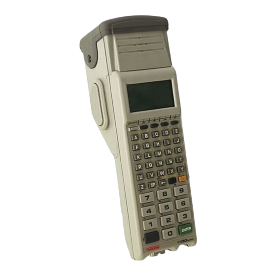
See Figure 1-1 for the location of these key components. Display On/Off Button General Information Radio Module Special Function Keys Alpha Numeric Keypad TM1100 Terminal Module Figure 1-1 RT1140 Terminal 1100 Series Data Terminal User’s Guide... -
Page 18: Terminal Keyboard
Terminal emulation is an application program that is loaded into your terminal. This program makes your 1100 terminal emulate (imi- tate) a terminal connected to your host computer, i.e. 5250, 3270, etc. Your terminal communicates directly to your host computer and re- ceives its direction from the host. -
Page 19: The Programmable Keys
User Manual Norand Part Number NPN: 961-051-002. On the following page is a graphic showing the keyboard layout for your terminal. Please refer to Appendix C for the overlay that supports the terminal emulation associated with your network. General Information 1100 Series Data Terminal User’s Guide... -
Page 20: Figure 1-2 Standard Keyboard Layout
ON/OFF Button CLEAR Key (Black) 1100 Series Data Terminal User’s Guide ENTER Figure 1-2 Standard Keyboard Layout Special Function Keys (Dark Gray) SHIFT Key (Black) SHIFT Key (Gold) ENTER... -
Page 21: Scrolling Keys
Your terminal has two types of annunciators. The first type alerts you of a condition that requires action on your part, or makes you aware of this action. Your 1100 Series data terminal has two such annunciators. General Information 1100 Series Data Terminal User’s Guide... - Page 22 The other type of annunciator alerts you to the status of communica- tions between your terminal and the host. Your 1100 Series data termi- nal offers the following annunciators of this type. Transmitting data.
-
Page 23: Terminal Buzzer
This technical jargon informs you to use scanners with the standard connector for 5-volt bar code scanners. Scanners you buy from Norand work with all our radio terminals unless specifically noted otherwise. General Information 1100 Series Data Terminal User’s Guide 1-11... -
Page 24: Charger Connector And Port For Data Cable
Backlight Your 1100 Series terminal has a backlight feature for those times when you cannot read the display. You can set the amount of time the back- light stays on before shutting off. This range is from 1 to 255 seconds. -
Page 25: Internal Memory
Replacement straps are available through Norand Sup- ply Sales. Internal Memory Your 1100 Series data terminal contains two types of internal memory. The first type is called volatile or pseudo-static Random Access Memory (RAM). Volatile (pseudo-static) RAM will not lose its contents if you turn your terminal off or if the terminal shuts down because your batteries go into low battery state. - Page 26 12 or 5-volt Flash. If the last three digits are -005 or greater, it contains 5-volt Flash ROM. If it is -004 or less, it contains a 12 volt-Flash ROM. 1100 Series Data Terminal User’s Guide 1-14...
-
Page 27: Terminal Operation
Please refer to Appendix A for more information regarding this choice. Terminal Operation " " " " " " " " " " 1100 Series Data Terminal User’s Guide Section 2 " " " " " " " " Ò 1100 Se-... -
Page 28: Battery Pack Installation
1/4 turn until the cam stops. Lift the battery compartment cover off the terminal case to get at the battery compartment. 1100 Series Data Terminal User’s Guide Top Hand Strap Clip Hand Strap Bottom Hand Strap... - Page 29 1/4 turn until it locks into place. Terminal Operation Battery Compartment Door NiCd Battery Pack Terminal Module Figure 2-2 Battery Pack Insertion 1100 Series Data Terminal User’s Guide...
-
Page 30: Charging The Battery Pack In The Terminal
The battery pack should be recharged whenever the low battery alert appears on the terminal display. NiCd batteries perform better and give more hours of operation between charges if recharged only when they have been fully discharged. 1100 Series Data Terminal User’s Guide To Terminal Charge Connector Figure 2-3... -
Page 31: Backlight Operation
Guides and Technical Overviews can be found in Appendix A, Ref- erence Material. If the host does not recognize your terminal, call your internal system administrator, your Norand Customer Support Specialist (CSS), or the Terminal Operation (Shift) key and the (Backlight) 1100 Series Data Terminal User’s Guide... -
Page 32: Cabling
NC100 charger. This charger is an unregulated power source and is designed for charging your terminal only. Refer to Figure 2-4 for connection information or refer to operating instructions that come with your charger. 1100 Series Data Terminal User’s Guide From NC100 Charger Figure 2-4... -
Page 33: Programming Your Terminal
SECTION 2 Programming Your Terminal Depending on the Flash ROM contained in your 1100 Series data ter- minal there are two different methods for programming your terminal in a terminal emulation mode. Data Terminal with 12-Volt FLASH ROM If your terminal contains 12-volt Flash ROM, programming requires using a regulated power supply, the NC1100 Power Supply and Char- ger, Norand Part Number, NPN: 851-022-001. -
Page 34: Data Terminal With 5-Volt Flash Rom
SECTION 2 Data Terminal with 5-Volt FLASH ROM If your 1100 Series data terminal contains 5-volt Flash ROM, you do not need to (and you cause no harm) use a special charger as with a termi- nal containing a 12-volt Flash ROM. To program your data terminal with 5-volt Flash ROM, you connect directly from your terminal to the host computer. -
Page 35: Terminal Operation
Terminal Operation ON/OFF NORAND CORPORATION COPYRIGHT 1991 Name Version Date: ddmmyy HOST: Protocol NATIVE Unit #: xxx 1100 Series Data Terminal User’s Guide key,... -
Page 36: Turning The Terminal Off
You turn your terminal OFF by pressing the terminal and releasing it. In some earlier models it is necessary to hold the ON/OFF key down for about two seconds until the terminal display goes blank. 1100 Series Data Terminal User’s Guide 2-10 ON/OFF... -
Page 37: Attaching A Bar Code Scanner
This section gives you an overview of the actions for using keys in set- ting or changing parameters on your 1100 Series data terminal. The descriptions that follow help you become familiar with the keys and their functions before you begin to change parameters. -
Page 38: Keyboard Functions
Various menus require entering a number, but do not necessarily have simple choices such as 1, 2, 3, 4, etc. Instead, you may have to enter a number from 0-32, or 1-255, or some other figure. 1100 Series Data Terminal User’s Guide 2-12... -
Page 39: Up And Down Arrows
These instances will be detailed in the text that applies to those menus, or in the menu displays. These keys are defined by the host computer that the 1100 Series data terminal is emulating. Use these keys to: Adjust the length and frequency of the audible (buzzer) func-... -
Page 40: Set-Up Parms
Radio communications (UHF model only) " Protocol options " After changes have been entered, perform a cold start. 1100 Series Data Terminal User’s Guide 2-14 ] then the black [ ] shift keys to call up the Main Menu 1) Set-up Parms... -
Page 41: More
Main Menu and select [6] to exit the operating system. More The More option leads you into a second main menu subroutine. In- cluded in this list of options are selections for: Terminal Operation 1100 Series Data Terminal User’s Guide 2-15... - Page 42 This option is password protected. The password procedure is the same as Set-up Parms. Session Menu. 1100 Series SST model only. Allows you to desig- " nate session switching parameters. Use the Session Menu to verify or change the current session before making parameter settings.
-
Page 43: Terminal Emulation Menu Screens
" " " " " " " " Terminal Emulation software. This section key to select the option that is highlighted in the 1100 Series Data Terminal User’s Guide Section 3 " " " " " " " " [ENTER]... -
Page 44: Setting The Operating Parameters
The Main Menu is the first screen displayed when you open the hand- held computer menus. All other menus are accessed from the Main Menu. After the Main Menu appears, enter a number (1 through 7) to make a selection. The Main Menu is shown below: 1100 Series Data Terminal User’s Guide... - Page 45 SECTION 3 Terminal Emulation Menu Screens Main Menu 1) Set-up Parms 2) LCD Parms 3) Beeper Setup 4) Tests 5) Version Info 6) Exit Menus 7) More 1100 Series Data Terminal User’s Guide...
- Page 46 [ENTER] key several times. You can then se- lect 6) Exit Menus, to return to the operating system. The following paragraphs describe options available from the Main Menu. 1100 Series Data Terminal User’s Guide Main Menu 1) Set-up Parms 2) LCD Parms...
- Page 47 LCD Parms (parameters) menu adjusts the following display (Liquid Crystal Display) parameters: Screen size (number of lines displayed and characters per line) " Cursor position (Screen Mode) " Uppercase display " Scrolling window parameters " Terminal Emulation Menu Screens 1100 Series Data Terminal User’s Guide...
- Page 48 The More option opens a menu called Main Menu 2, which lets you (1) set a keyboard “type-ahead” option, (2) save parameter settings as the new hand-held computer default parameters, and (3) designate session switching parameters. 1100 Series Data Terminal User’s Guide...
-
Page 49: Opening The Set-Up Parms Menu
Press the [1] key. Press the [ENTER] key. At the prompt, enter the password CR52401. The Set-Up Parms menu, and the menus you can access from it, are shown on the following page. Terminal Emulation Menu Screens 1100 Series Data Terminal User’s Guide... - Page 50 5) 3270 6) VT220 7) Native Radio Comm 1) SST 2) SST-Diag Mode 3) Security ID 1100 Series Data Terminal User’s Guide Set-up Parms 1) Radio # 2) Barcode Parms 3) Protocol Opts 4) Display Opts 5) Radio Comm 6) Cold Start 7.
- Page 51 A. If host A is not available, the hand- held computer seeks host B; if host B is not available, the hand-held computer attempts to log onto host C. When designating additional hosts, you must: 1100 Series Data Terminal User’s Guide...
- Page 52 RADIO MODULE Set Mode/Channel Use Cursor Up and Down Keys To Adjust DS xxxK Channel xx ENTER (continue to next page) 1100 Series Data Terminal User’s Guide 3-10 Radio # Enter Unit Number: Press A for Advanced Setup Advanced Setup...
- Page 53 1) Host A 2) Host B 3) Host C (1) ENTER Host 1) Native 2) 3270 3) 5250 4) VT220 ENTER Host Enter Unit Number: ENTER Host (host emulation) Unit# Enter Host Name: xxxx 1100 Series Data Terminal User’s Guide ENTER 3-11...
- Page 54 Scan Options Use the Scan Options menu to designate how the hand-held computer handles scanned bar codes. The Scan Options menu is shown below. Descriptions of the options follow. 1100 Series Data Terminal User’s Guide 3-12 [ENTER] key. The next...
- Page 55 After you press the [ENTER] key, the display advances to additional Scan Options menus. Terminal Emulation Menu Screens Scan Options 1) Redundancy 2) MOD 10 Check 3) Concatenate 4) BC Type Char 5) Stream Scan 6) Scan All Flds 7) More 1100 Series Data Terminal User’s Guide 3-13...
- Page 56 Scan Options menu by pressing the [ENTER] key. The Scan Options menu, and the bar code symbologies you can enable from it, are shown here. 1100 Series Data Terminal User’s Guide 3-14 Scan Options 2) Scan PreChar...
- Page 57 Scan Options 1) UPC 2) EAN 3) Code 39 4) Code 128 5) Codabar 1) Enabled 2) Add-On 2 3) Add-On 5 4) Expand 8To13 Code 128 1) Enabled 2) UCC/EAN Codabar 1) Codabar 1100 Series Data Terminal User’s Guide 3-15...
- Page 58 The length options must be set for each enabled bar code. Instructions for setting the length options follow on the next page. 1100 Series Data Terminal User’s Guide 3-16 Scan Options (2)
- Page 59 Fix Length 3 (bar code type) Max Length Min Length Fix Length 1 Fix Length 2 Fix Length 3 Fix Length 4 (bar code type) Drop Leading (bar code type) Drop Leading Drop Trailing 1100 Series Data Terminal User’s Guide 3-17...
- Page 60 After you have set all of the length options for the enabled bar code the display returns to one of the Scan Options menus (depending on which menu you enabled the bar code from). 1100 Series Data Terminal User’s Guide 3-18 [ENTER]...
-
Page 61: Protocol Options
The Protocol Opts menu is shown below. Terminal Emulation Menu Screens Protocol Opts 1) Host View Sze 2) Data Stream 3) Extended Cmds 4) 5250 5) 3270 6) VT220 7) Native 1100 Series Data Terminal User’s Guide 3-19... - Page 62 5250 Terminal Emulation with error messages. Host View Sze Width To change the width, enter a number (between 1 - 80). Press [EN- TER]. and return to the Protocol Opts menu. 1100 Series Data Terminal User’s Guide 3-20...
- Page 63 Press [ENTER] to return to the Protocol Opts menu. Terminal Emulation Menu Screens Data Stream 1) Native 2) 3270 3) 5250 4) VT220 Extended Cmds 1) Enabled 2) Disabled 1100 Series Data Terminal User’s Guide 3-21...
- Page 64 Press [1] to enable the Beep On Error option. Press [2] to enable the Auto Tab Scan option. Press [3] to enable the Telnet option. Press [ENTER] to return to the Protocol Options menu screen. 1100 Series Data Terminal User’s Guide 3-22 5250 Options 1) Beep On Error...
- Page 65 Telnet allows for the handling of telnet option negotiations to establish a session with an appropriate telnet server. Terminal Emulation Menu Screens 3270 1) Keybrd Unlock 2) Auto Tab Scan 3) Auto Entr Scn 4) Emulate 3210 5) Telnet 1100 Series Data Terminal User’s Guide 3-23...
- Page 66 For full 3210 compatibility: you must disable buffering the key- board, set cursor to lazy mode, and set the LCD Parms to Key Uppercase. After enabling the desired 3270 options, press the [ENTER] key to return to the Protocol Opts menu. 1100 Series Data Terminal User’s Guide 3-24...
- Page 67 The Auto Entr Scan and Auto Tab Scan options cannot be enabled at the same time. Terminal Emulation Menu Screens VT220 1) DEL to BS 2) CR to CRLF 3) Auto Entr Scn 4) Auto Tab Scan 5) Local Echo 6) AnswerBack 7) More 1100 Series Data Terminal User’s Guide 3-25...
- Page 68 You can get a command from the host that defines the Function keys. If UserKey Locked is set the host ignores this command while this option is set. 1100 Series Data Terminal User’s Guide 3-26 VT220 1) Screen Lock...
- Page 69 Protocol Opts menu. Terminal Emulation Menu Screens RS232 1) RS232 Baud Rate 2) RS232 Parity 3) RS232 Stop Bits 4) RS232 Data Bits 5) RS232 Flow VT220 Mode 1) Char 2) Block 1100 Series Data Terminal User’s Guide 3-27...
- Page 70 When enabled, pressing <F1> is equivalent to pressing Blue-0, while pressing <F2> is equivalent to pressing Blue-1, etc. When disabled, <F1> is equivalent to Blue-1, and <F2> is equivalent to Blue-2, etc. Native 1) F1 is FUNC-0 1100 Series Data Terminal User’s Guide 3-28...
-
Page 71: Display Options
Terminal Emulation Menu Screens Display Opts 1) Backlight 2) Cursor Mode Backlight Timer Use Cursor Up And Down Keys To Adjust and down arrows to select a number from Off to 1100 Series Data Terminal User’s Guide 3-29... -
Page 72: Radio Comm
Diagnostic modes disable data compression and are reserved for engineering tests. Selecting option 3, allows you to change the radio security identifica- tion. You can enter up to 16 characters to establish this security ID. 1100 Series Data Terminal User’s Guide 3-30 Cursor Mode 3) Underline 4) Block >... -
Page 73: Cold Start
The default is to have this option disabled. Terminal Emulation Menu Screens Security ID Old Security ID New Security ID New Security ID Cold Start Enter “Y” to Cold Start terminal: 1100 Series Data Terminal User’s Guide 3-31... -
Page 74: Lcd Parms
The screen mode (how the cursor positions itself on the display) " Turn the backlight On or Off " Making all alphabetic character keystrokes uppercase charac- " ters Scrolling window parameters " 1100 Series Data Terminal User’s Guide 3-32 Set-up Parms 1) Menu Password... -
Page 75: Screen Size
When the word ON appears in the position corresponding to the desired screen size, press the [ENTER] key. Terminal Emulation Menu Screens LCD Parms 2) Screen Size 3) Screen Mode 6) Key Uppercase 7) Scroll Window Select Size 1100 Series Data Terminal User’s Guide 3-33... -
Page 76: Screen Mode
(the cursor no longer remains in the corner of the display). When the cursor reaches the CRT screen boundary it stops moving. The cursor does not wrap to the next line in the display. An error tone sounds if 1100 Series Data Terminal User’s Guide 3-34 Screen Mode... -
Page 77: Key Uppercase
Scroll Window Menu items are: (1) Tab Size, (2) Screen Size, (3) Define Width, and (4) Define Height. Choices 1 and 2 allow you to define the size (tab or Terminal Emulation Menu Screens 1100 Series Data Terminal User’s Guide 3-35... -
Page 78: Beeper Setup
The frequency of the tone is adjustable in steps from 0 to 32. The length is adjustable in steps from 0 to 10. The Key Click menu screen and subscreens are shown below. 1100 Series Data Terminal User’s Guide 3-36 Scroll Window... - Page 79 Terminal Emulation Menu Screens Key Click 2) Length 3) Frequency Frequency Use Cursor Up and Down Keys To Adjust Key Click> keys to make the desired adjustment. 1100 Series Data Terminal User’s Guide 3-37...
-
Page 80: Tests
RS-232, which tests the communication port on the hand-held " computer. Display, which tests the operation of the hand-held computer " display. 1100 Series Data Terminal User’s Guide 3-38 Beeper Setup 1) Beep Internal 2) Beep Head Set Tests 1) Peripherals... - Page 81 " The CTS output to the RTS input " The RS232 Test screens are shown below. Terminal Emulation Menu Screens Peripherals 2) RS232 Test 3) Display Test 4) Keyboard Test 5) Scanner Test 1100 Series Data Terminal User’s Guide 3-39...
- Page 82 RS232 Test menu (shown above) The condition of each line-pair displays as passing or failing the test. If any test fails, the hand-held computer should be returned for service. 1100 Series Data Terminal User’s Guide 3-40 RS232 Test...
- Page 83 Visually inspect the painted black lines. For the test to pass, the screen should be uniformly black; press [ENTER]. You return to the Peripherals menu. Terminal Emulation Menu Screens 1100 Series Data Terminal User’s Guide 3-41...
- Page 84 For this test to pass the bar code and the bar code length should ap- pear on the display. Press any key to exit. The Scanner Test screen is shown below. 1100 Series Data Terminal User’s Guide 3-42 Keyboard Test...
-
Page 85: Memory View
The Packet Driver tests allow you to test the accuracy of data transmis- sions to and from the hand-held computer. Terminal Emulation Menu Screens Memory View Exit Heap Far Heap Memory Dump Address: XXXXXX Packet Driver 3) Packet Stats 4) Histogram 1100 Series Data Terminal User’s Guide 3-43... - Page 86 Packet Stats The Packet Stats (statistics) test shows the number of packets sent and received, number of errors, and number of packets dropped. Lost Qty/Min 1100 Series Data Terminal User’s Guide 3-44 Receive Statistics Transmit Statistics Transaction Statistics RTC Statistics * SEE TEXT ‘HISTOGRAM...
-
Page 87: Histogram Opts
" reset count " interval time " time bucket # " A Norand engineer works with you on these selections. Terminal Emulation Menu Screens Histogram Opts 1) Start 2) Stop 3) View 1100 Series Data Terminal User’s Guide 3-45... -
Page 88: Numbers
* Radio models 1160, 1170, 1180, and 1190 Exit Menus The Exit Menus option (#6) exits you from this terminal emulation sec- tion and returns you to the screen you were at before entering this sec- 1100 Series Data Terminal User’s Guide 3-46 Version Info Firmware name... -
Page 89: More
This lets you key in information when the hand-held computer cannot immediately send data to the host computer. Terminal Emulation Menu Screens Main Menu 2 1) Keyboard Opts 2) Save Parms 4) Session Menu Keyboard Opts 1) Type-Ahead 1100 Series Data Terminal User’s Guide 3-47... -
Page 90: Save Parms
Parms, you are prompted to enter a seven-character password (CR52401), as shown in the following. Once the password is correctly entered, the hand-held computer automatically saves (writes to EE- PROM) the parameters. 1100 Series Data Terminal User’s Guide 3-48 Save Parms Enter Password >... -
Page 91: Cloning Opts
Cloning Opts Cloning Opts (Options) allow you to transfer the application program or parameter settings from one 1100 Series data terminal to another. Each of three choices is password protected. The password is CR52401. To perform this function you need a cloning cable and both terminals must be set up for cloning. -
Page 92: Figure 3-2 5-Volt Flash Cloning Cable Connection
Terminals with 12-volt FLASH use Norand Part Number, NPN: 216-911-001. Data Terminals with 5-volt FLASH use Norand Part Number, NPN: 216-909-001. With both terminals turned ON, Press 3 (Cloning Opts) on both terminals. 1100 Series Data Terminal User’s Guide 3-50 To Receiving Terminal Figure 3-2 Figure 3-3... -
Page 93: Session Menu
When the desired key displays, press [ENTER] to set your selection. The Set Hot Key option is only available on hand-held computers that support session switch- ing. Terminal Emulation Menu Screens 1100 Series Data Terminal User’s Guide 3-51... - Page 94 To Adjust Session: Host: <Datastream> “COPY SETUP” COPIES PA- RAMETERS OF BACK- GROUND SESSION TO THE CURRENT SESSION. 1100 Series Data Terminal User’s Guide 3-52 Session Menu 1) Switch 2) Set Hot Key 3) Copy Setup “Copy Setup” is password...
-
Page 95: Module Replacementt
Introduction This section includes instructions for all radio modules compatible with your 1100 Series data terminal. Shown below are the labels that warn you of the danger using laser scanners. Before using your scan- ner, read all labels to become familiar with exposure risks. - Page 96 Subchapter J. No controls are provided for operation or maintenance. Laser light in excess of Class II is present inside the internal protective cover. DO NOT stare into beam if protective cover is removed. 1100 Series Data Terminal User’s Guide...
-
Page 97: Series Data Terminal User's Guide
(2) This device must accept any interference received, including interference that might cause undesired operation. LASER STRAHLEN TN1- -976- -011 1100 Series Data Terminal User’s Guide Module Replacement U.S. Pats. 4758717; 5017765; 5047617; 4716354; 4845419; 5070536; 3991299;... -
Page 98: Electrostatic Safe Environment
Unscrew (counterclockwise) the vertical external antenna from your RT1100 terminal, (Figure 4-1). If your terminal does not contain an ex- ternal antenna, proceed to the next section Radio Module Removal. 1100 Series Data Terminal User’s Guide Unscrew Antenna Figure 4-1... -
Page 99: Radio Module Removal
Squeeze the handstrap clips, and slide the top hand strap clip out of the retaining brackets. (See Figure 4-2) Remove the battery compartment cover by turning the cam lock counterclockwise 1/4 turn. Module Replacement Handstrap Clip Handstrap Figure 4-2 Handstrap Removal 1100 Series Data Terminal User’s Guide Bottom Handstrap Fastener... - Page 100 Bear down slightly on your radio module, while gently pulling it straight out, then up and away from your terminal module. Radio Module Two screws, one on each side 1100 Series Data Terminal User’s Guide Battery Compartment Door Terminal Module Figure 4-3...
-
Page 101: Sst Radio Module Replacement
Refer to the instructions for removing the radio module and re- placing it with your new radio module. Module Replacement 1100 Series Data Terminal User’s Guide... - Page 102 When installed properly, the interconnect board fits flush against the CPU board in your terminal. The pins on the interconnect board fit all the way into the con- nector when completed. 1100 Series Data Terminal User’s Guide Interconnect Board Interconnect...
- Page 103 While pressing the hand strap release clips, slide the hand strap clip into the retaining brackets. Be sure the clips snap into place. Module Replacement Figure 4-5 Interconnect Board Fit 1100 Series Data Terminal User’s Guide...
-
Page 104: Figure 4-6 Rm80/90 Module
NORAND Power up your terminal and perform tests on your terminal described in Section 2, Periphperals, to ensure that the new radio module works properly. 1100 Series Data Terminal User’s Guide 4-10 Figure 4-6 RM80/90 Module... -
Page 105: Uhf Radio With Integrated Scanning Module Replacement
(See Figure 4-7) Slide the interconnect board into the recessed opening of the component cover on the host board. Gently wiggle the board side to side to start it into the connector. Module Replacement 1100 Series Data Terminal User’s Guide 4-11... - Page 106 " NOTE: When completely pushed into place, the interconnect board fits flush against the CPU board in your terminal. Captive Screw Alignment Handle 1100 Series Data Terminal User’s Guide 4-12 Interconnect Board Interconnect Board Connectors Figure 4-7...
- Page 107 NORAND ADK Programming application. Power up your terminal and perform tests on your terminal de- scribed in Section 2, Peripherals, to ensure that the new radio module with integrated scanning works properly. Module Replacement 1100 Series Data Terminal User’s Guide 4-13...
- Page 108 Module Replacement SECTION 4 1100 Series Data Terminal User’s Guide 4-14...
-
Page 109: Maintenance And Troubleshooting
The following paragraphs include maintenance procedures to perform to keep your terminal in good working order. " " " " " " " " " " Ò 1100 Series data terminal. 1100 Series Data Terminal User’s Guide Section 5 " " " " " " " "... -
Page 110: Battery Pack
Maintenance and Troubleshooting " Battery Pack The battery pack in the 1100 Series data terminal is a rechargeable Nickel-Cadmium (NiCd) type. The display will tell you when it is time to recharge the battery pack. You can charge the battery pack either in your terminal or by remov- ing it and placing it in a pack charger. -
Page 111: Handstrap
Line up the new handstrap, push down and reinsert screws. Slide the top handstrap clip back into the retaining brackets. Push the top handstrap clip down into the brackets so that it locks into place. 1100 Series Data Terminal User’s Guide Maintenance and Troubleshooting "... -
Page 112: Case Cleaning
After the battery pack compartment is completely dr y, reinstall the battery pack, then turn your terminal ON to see that it oper- ates properly. 1100 Series Data Terminal User’s Guide... -
Page 113: Troubleshooting The Terminal
Maintenance and Troubleshooting " Troubleshooting the Terminal When properly maintained and cared for, your 1100 Series data termi- nal should provide trouble-free operation. If a problem develops, use the following troubleshooting procedures to isolate the problem. Usu- ally, these procedures help you isolate the problem to the terminal or another component of your network. -
Page 114: Troubleshooting Procedures
These can be found on a label on the back of your terminal un- der the handstrap. Description of the problem(s) you are having. " Description of the steps you have taken to isolate the problem, " and the results of those steps. 1100 Series Data Terminal User’s Guide... - Page 115 If this does not solve the problem call the 24-hour Norand Cus- tomer Support Hot-Line 1-800-221-9236 U.S. or 1-800-663-6149 in Canada, for help. 1100 Series Data Terminal User’s Guide Maintenance and Troubleshooting "...
- Page 116 9. Check your base radio LED indicators. If working properly, the green power LED, yellow RF LED, and green NET LED should all be ON. The yellow status LED should be OFF, this LED comes on only when the base fails. 1100 Series Data Terminal User’s Guide...
-
Page 117: Returning A Module For Service
The bar code scanner does not work; scanner attached to the terminal does not operate or does not read some bar codes. Your 1100 Series data terminal is only compatible with 5 volt bar code scanners. Attach a known-good scanner to your terminal and try again. If this corrects the problem, replace the defective scanner. - Page 118 SECTION 5 Maintenance and Troubleshooting " 5-10 1100 Series Data Terminal User’s Guide...
-
Page 119: Terminal Specifications
This appendix contains the specifications for your NO- Ò RAND 1100 Series data terminal. Included are the envi- ronmental conditions (temperature range, humidity) to safely operate your terminal in, the environmental condi- tions required for battery pack charging, the physical and... -
Page 120: Environmental
" FLASH ROM: 512 K bytes, user accessible " Masked: 512 K bytes, reserved for operating system, " diagnostic tests, character fonts, etc. 1100 Series Data Terminal User’s Guide ° ° F (0 to 50 ° ° F (-30 to 70 °... -
Page 121: 1100 Sst Specifications
Docket 87-389 and is not affected by section 15.37 gov- erning transition. Spread Method: direct sequence " ° ° F (0 to 50 ° ° F (-30 to 70 ° ° F (5 to 40 1100 Series Data Terminal User’s Guide... -
Page 122: Memory
Alexander Optimizer and Cycle Charger, time is 1 1/2 hours. In Terminal, using an NC100 Charger: Approximately " 10-14 hours (overnight), depending on the condition of the battery and the activity of the terminal. 1100 Series Data Terminal User’s Guide... -
Page 123: Recommended Battery Pack Chargers
Alexander Optimizer, 1 pack cycle charger " Norand Part Number, NPN: 852-015-001 Alexander Optimizer, 3 pack cycle charger " Norand Part Number, NPN: 852-015-003 Alexander Optimizer, 6 pack cycle charger " Norand Part Number, NPN: 852-015-006 1100 Series Data Terminal User’s Guide... -
Page 124: Ccd Scanner Specifications
Read Element: 2048 bit Charged Coupled Device " (CCD) Scan rate: 50 scans per second (sps) " Reading Conditions Skew: ¦ 65_ " Pitch: ¦ 45_ " Ambient light tolerance: " Incandescent: 3,000 lux Fluorescent: 1,500 lux 1100 Series Data Terminal User’s Guide... -
Page 125: Vld Scanner Specifications
Standard Range Scan Rate: 55 scan per second (sps) " Long Range and VIN Scan Rate: 36 scans per second " (sps) Reading Conditions Pitch: ¦ 55_ " Skew: ¦ 65_ " Ambient light tolerance: " Incandescent: 3,000 lux Fluorescent: 1,500 lux 1100 Series Data Terminal User’s Guide... -
Page 126: Depth Of Field (Dof)
" Reference Manual, Norand Part Number, NPN: 961-051-001 Application Development Kit (ADK) Programmer’s " User Manual, Norand Part Number, NPN: 961-051-002 1100 Series Data Terminal User’s Guide Table A-1 Depth of Field (DOF) Standard DOF LR DOF (inches) (inches) 2 - 7.5... - Page 127 VT/ANSI Terminal SST Technical Overview, " Norand Part Number, NPN: 977-047-031 NLAT Installation and Operations Guide, " Norand Part Number, NPN: 977-047-052 VT NTELNET Installation and Operations Guide, " Norand Part Number, NPN: 977-047-043 1100 Series Data Terminal User’s Guide...
-
Page 128: Product Accessories
SH1000 Scanning Handle: Mechanically snaps on to " the terminal (no screws required) and does not require electrical connection. Norand Part Number, NPN: 709-861-001 Various Cables: Work with your Norand sales team to " determine your needs. A-10 1100 Series Data Terminal User’s Guide... -
Page 129: Bar Code Symbologies
" Introduction This appendix contains a brief explanation of each bar code symbology that your 1100 Series data terminal decodes. This section explains some of the general characteristics and uses of these bar code types. Specific bar code algorithms are enabled either from the host computer, or by you using the setup menus. -
Page 130: Table B-1 Bar Code Data String Formats
*If MOD 10 or MOD 11 check digits are enabled, the digit falls at the end of a bar code data string. Each check digit enabled extends the length of the bar code data string by 1 character. 1100 Series Data Terminal User’s Guide Table B-1 **Data Format... -
Page 131: Bar Code Symbology
= start and stop digits " Bar Code Symbology The 1100 Series data terminal is programmed to recognize 11 of the most widely used bar code symbologies. With bar code symbologies, like languages, there are many different types. A new bar code symbology is designed to provide the flexibility required for a particular application or inventory tracking system. -
Page 132: Upc
General merchandise stores " Some retail items are so small that a standard UPC bar code cannot fit on the packaging. When this occurs there is a shorter version of the UPC symbology that is permitted. 1100 Series Data Terminal User’s Guide... -
Page 133: Ean
Any of the start or stop characters may be used on either end of the symbol, thereby, it is possible to use the 16 unique start or stop combinations to identify label type or other information. 1100 Series Data Terminal User’s Guide... -
Page 134: C11 (Code 11)
The main feature of this symbology is the ability to encode messages using the full alphanumeric character set, seven special characters, and ASCII characters. 1100 Series Data Terminal User’s Guide... -
Page 135: Extended Code 39, Also Called Concatenation
Encoded Code 39, also called Full ASCII If the bar code reader has been programmed for the task, it is possible to encode the entire ASCII character set (128 1100 Series Data Terminal User’s Guide... -
Page 136: C93
C128 (Code 128) is one of the newest symbologies used by the retail and manufacturing industries. It was designed in response to the need for a compact alphanumeric bar code symbol that could encode complex product identification. 1100 Series Data Terminal User’s Guide... - Page 137 Because this “random” data may be mistaken later for an industry standard code format, the UCC and EAN chose a symbology which can be uniquely identified from these oth- er bar codes. This standard has been designed for maximum 1100 Series Data Terminal User’s Guide...
- Page 138 UCC/EAN standards are designed primarily for identifica- tion of products. Several industries expressed the need to standarize more than product identification. The UCC/EAN Code 128 Ap- plication Identifier Standard supplies this tool. The stan- B-10 1100 Series Data Terminal User’s Guide...
-
Page 139: Of 5 (Straight 2 Of 5)
Because the white spaces carry no information, their dimensions are not criti- cal. The code 2 of 5 code is self-checking, meaning a scanner passing through a printing void would detect the proper ra- 1100 Series Data Terminal User’s Guide B-11... - Page 140 2 of 5 family while encoding information in both the black bars and the white spaces. Such an encoding tech- nique eliminates the inter-element spaces. B-12 1100 Series Data Terminal User’s Guide...
-
Page 141: Plessey
Plessey codes are not self-checking and employ a variety of check characters. This symbology is very limited about what information can be encoded. It is not considered for new applications. 1100 Series Data Terminal User’s Guide B-13... - Page 142 Bar Code Symbologies APPENDIX B B-14 1100 Series Data Terminal User’s Guide...
-
Page 143: Keyboard Overlays
" " " " " " " " " " " " " " " " " " " This appendix provides overlays for Native, 3270, 7527, PC/ AT, VT220, and 5250 host emulations. 1100 Series Data Terminal User’s Guide... -
Page 144: Figure C-1 3270 Keyboard And Overlay
1100 Series Data Terminal User’s Guide ON/OFF C. SEL. SHIFT @ F2 % F10 / F11 & F12 ; F13 . F14 : F15 ? F22 = F23 HOME ! DEL CLR MENU INSERT CLEAR PA1 ENTER Figure C-1 3270 Keyboard and Overlay... -
Page 145: Figure C-2 5250 Keyboard And Overlay
F22 = F23 < F24 > HEX | HOME ! MENU SYS REQ ‘ PRINT | ROLL ERASE INPUT INSERT ROLL ATTN CLEAR HELP FIELD- - FIELD+ ENTER Figure C-2 5250 Keyboard and Overlay W = WINDOW 1100 Series Data Terminal User’s Guide ¢... -
Page 146: Figure C-3 Native Keyboard And Overlay
1100 Series Data Terminal User’s Guide ON/OFF & ” DEL CLR MENU ENTER Figure C-3 NATIVE Keyboard and Overlay... -
Page 147: Figure C-4 7527 Keyboard And Overlay
ON/OFF RESET SHIFT F14 : F15 ? & F22 = F24 FILL HOME ! DEL CLR PF MENU CANCEL ENTER Figure C-4 7527 Keyboard and Overlay W = WINDOW 1100 Series Data Terminal User’s Guide... -
Page 148: Figure C-5 Pc/At Keyboard And Overlay
1100 Series Data Terminal User’s Guide ON/OFF RESET SHIFT SHIFT @ F3 & F8 F10 ) ‘ ” ’ < > ScrLk PrtSc Break NumLk SysReg MENU HOME PGUP PGDN ENTER Figure C-5 PC/AT Keyboard and Overlay W = WINDOW... -
Page 149: Figure C-6 Vt220 Keyboard And Overlay
INSERT SELECT PREV SCRN SHIFT VT220 is a registered trademark of D igital Equipment Corporation Figure C-6 VT220 Keyboard and Overlay W = WINDOW 1100 Series Data Terminal User’s Guide F10 / F15 ? F20 ” MODE > REMOVE NEXT SCRN... - Page 150 Keyboard Overlays APPENDIX C 1100 Series Data Terminal User’s Guide...
-
Page 151: Connectors And Pin Definitions
9-Pin D-Sub 9-PIN D-SUB PIN NUMBER SIGNAL NAME SSOS S DATA SCNLED N.U. TRIGGER ENABLE V SCAN+ Figure D-1 TM1100 Connector End View 9-Pin D-Sub 1100 Series Data Terminal User’s Guide Appendix D " " " " " " " "... -
Page 152: Figure D-2 Tm1100 Connector End View 6-Pin Mini-Din
1100 Series Data Terminal User’s Guide 6-Pin Mini-DIN 6-PIN MINI-DIN PIN NUMBER SIGNAL NAME ETXDA ERXDA ERTSA ECTSA Figure D-2 TM1100 Connector End View 6-Pin Mini-DIN... -
Page 153: Figure D-3 Tm1100 Surface Contact Pin Descriptions
Handstrap Figure D-3 TM1100 Surface Contact Pin Descriptions 1100 Series Data Terminal User’s Guide GROUND TXD/485B RXD/485A NOT USED NOT USED CHARGE... - Page 154 Connectors and Pin Definitions APPENDIX D 1100 Series Data Terminal User’s Guide...
-
Page 155: Table E-1 Scanner Modes
Enables laser emulation scanner if trig- ger is detected Illuminate scan- Enables laser ners GOOD scanner if trig- READ LED ger is detected 1100 Series Data Terminal User’s Guide Appendix E Operation " " " " " " " "... -
Page 156: Pen Wands
A laser scanner sends a trigger signal to the terminal, but will not begin scanning until the terminal supplies an en- able signal back to the scanner. Only then will the scanned data be sent to the terminal. 1100 Series Data Terminal User’s Guide... -
Page 157: Wand Emulation Scanners
PSC53X2 Series, LS2010, and NTS/HLT-1125 Linker CCD Scanner. Earlier editions of this User’s Guide listed supporting the LS8510 scanner. The 1100 Series data terminals no longer support using the LS8510 scanner. In wand emulation scanners, an immediate scan occurs if the trigger is pulled while power is applied. - Page 158 Scanner Specification and Operation APPENDIX E 1100 Series Data Terminal User’s Guide...
Need help?
Do you have a question about the 1100 Series and is the answer not in the manual?
Questions and answers