Sign In
Upload
Download
Table of Contents
Contents
Add to my manuals
Delete from my manuals
Share
URL of this page:
HTML Link:
Bookmark this page
Add
Manual will be automatically added to "My Manuals"
Print this page
×
Bookmark added
×
Added to my manuals
Manuals
Brands
DALBO Manuals
Farm Equipment
LEVELFLEX 150
Manual
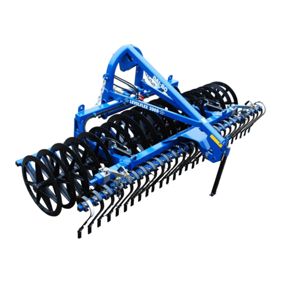
DALBO LEVELFLEX 150 Manual
Hide thumbs
1
2
3
Table Of Contents
4
5
6
7
8
9
10
11
12
13
14
15
16
17
18
19
20
21
22
23
24
25
26
page
of
26
Go
/
26
Contents
Table of Contents
Bookmarks
Table of Contents
Table of Contents
Use in Farming
Coupling and Uncoupling
Coupling
The Angle of the Lift Arms
Hydraulics
Uncoupling
Handling Without Use of the Three-Point Linkage
Operation
Transport Lock
Adjustment
Hydraulics
Running
Operating Speed
Scrapers
Maintenance
In General
Backlash in the Rings
Cleaning and Maintenance
Optional Equipment
Crackerboard
Running
Hydraulics
Adjustment
Efficiency
Refitting
Maintenance
Indication Lights
Repair
Replacement of Bearings Shafts Rings
Solid Model W. 80 and 90 CM Rings
Solid Model M. Crosskillring
Hyd. Model W. 80 CM Rings
Hyd. Model W. Crosskillring
Replacement of the Nylon Rail
Replacement of the Cylinders for Raising and Lowering the Side Sections
Replacement of the Set of Packings
Mounting
Replacement of the Cylinders for the Crackerboard
Replacement of the Set of Packings
Mounting
Scrapping
Spareparts
Advertisement
Quick Links
Download this manual
LEVELFLEX
GB
150, 260, 300 and 400 cm solid frame
400, 450 and 600 cm hydraulic frame
Table of
Contents
Previous
Page
Next
Page
1
2
3
4
5
Advertisement
Table of Contents
Need help?
Do you have a question about the LEVELFLEX 150 and is the answer not in the manual?
Ask a question
Questions and answers
Related Manuals for DALBO LEVELFLEX 150
Farm Equipment DALBO MAXICUT 260 Series Manual
(32 pages)
Farm Equipment DALBO MAXIDISC 300 Operator's Manual
(27 pages)
Farm Equipment DALBO 300 Manual
(26 pages)
Farm Equipment DALBO 300 Manual
Front-mounted grubber (25 pages)
Farm Equipment DALBO FARMERDISC 300 Manual
(24 pages)
Farm Equipment DALBO MAXIROLL 1030 Manual
(42 pages)
Farm Equipment DALBO MAXIROLL 950 Manual
(40 pages)
Farm Equipment DALBO POWERROLL 1430 Manual
(34 pages)
Farm Equipment DALBO POWERROLL 1830 Manual
(34 pages)
Farm Equipment DALBO LEVELFLEX 300 Manual
(26 pages)
Farm Equipment DALBO LEVELFLEX 600 Manual
(26 pages)
Farm Equipment DALBO MINIMAX 450 User Instructions
(49 pages)
Farm Equipment DALBO MAXICUT 920 Manual
(49 pages)
Farm Equipment DALBO MINIMAX 950 User Instructions
(44 pages)
Farm Equipment DALBO MINIMAX 450 User Instructions
(48 pages)
Farm Equipment DALBO MINIMAX 830 2008 Manual
(29 pages)
This manual is also suitable for:
Levelflex 260
Levelflex 300
Levelflex 400
Levelflex 450
Levelflex 600
Table of Contents
Print
Rename the bookmark
Delete bookmark?
Delete from my manuals?
Login
Sign In
OR
Sign in with Facebook
Sign in with Google
Upload manual
Upload from disk
Upload from URL


Need help?
Do you have a question about the LEVELFLEX 150 and is the answer not in the manual?
Questions and answers