
Related Manuals for Tyco iSTAR Ultra G2


Summary of Contents for Tyco iSTAR Ultra G2
- Page 1 Ultra G2 Controller Quick Start Guide September 2021 Document Number: 8200-1995-01 Revision:A0 www.swhouse.com...
- Page 2 © 2021 Johnson Controls. All rights reserved. JOHNSON CONTROLS, TYCO and SOFTWARE HOUSE are trademarks of Johnson Controls.
- Page 3 ■ Up to 4 Access Control Modules (ACM), or up to 32 IP-ACM Ethernet Door Modules. The iSTAR Ultra G2 is supported on C•CURE 9000 v2.90 SP2, and later, with firmware version 6.8.5 and higher. The iSTAR Ultra G2 is supported on C•CURE 9000 v2.70, and later, for Ultra mode only.
-
Page 4: Specifications And Requirements
Relay Ports (Wet - Primary and Secondary) Primary: 12 - 24 VDC +/- 15% (0.75 A) Electrical Output Secondary: 12 - 24 VDC +/- 15% (0.75 A) Voltage tolerances are 85% - 100% of listed specifications. NOTE iSTAR Ultra G2 Controller Installation and Configuration Guide... - Page 5 ■ When purchased separately, the iSTAR Ultra G2 modules must be installed in an enclosure which has an electrically supervised tamper switch to maintain UL compliance. ■ For Proprietary Burglar Alarm installations, the iSTAR Ultra G2 must be installed in accordance with UL 681 - Standard for Installation and Classification of Burglar and Hold-Up Alarm Systems.
- Page 6 ■ Built-in LEDs indicate the Ethernet Link and Receive Data signals. Encryption ■ TLS v1.3 encryption in iSTAR Ultra G2 mode. ■ TLS v1.2 encryption and unencrypted option in iSTAR Ultra mode. Wiring Specifications and Components Table 2: iSTAR Ultra G2 and Components Wiring Specifications...
-
Page 7: Installation
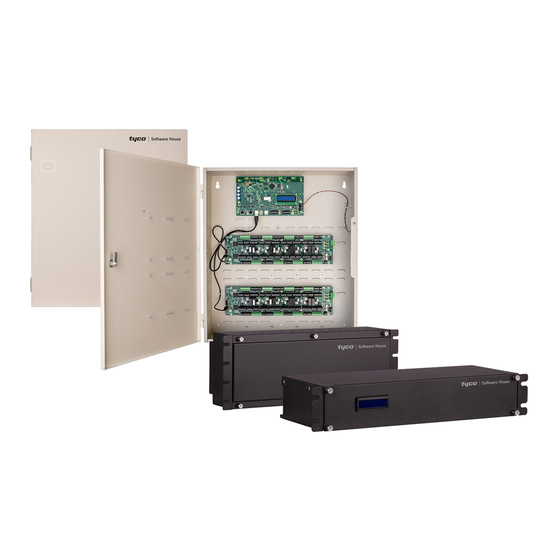
Installation You can mount the iSTAR Ultra G2 enclosure directly to a wall or uni-strut using suitable user-supplied hardware. Alternatively, you can mount the iSTAR Ultra G2 GCM and ACM in a standard 19-inch rack system. The system must be installed indoors within a protected premises in accordance with the National Electrical Code (NFPA70), and NOTE relevant local authority regulations. - Page 8 Figure 1: iSTAR Ultra G2 Enclosure Table 3: iSTAR Ultra G2 Enclosure Callouts Callout Description Keyhole Mounting Slot iSTAR Ultra G2 GCM Cabinet Enclosure 1.125" (29.565mm) Knockouts (0 top, 3 each side, 2 bottom) Tamper switch iSTAR Ultra G2 Controller Installation and Configuration Guide...
- Page 9 Ultra G2 ACM Ground (12) AC Knockouts (each side) Lower Mounting Hole 2" (50.8mm) Knockouts (2 top, 4 bottom, 4 left side, 5 right side) Ground stud (6-32) for shield wire. iSTAR Ultra G2 Controller Installation and Configuration Guide...
- Page 10 The General Control Module (GCM) is a general purpose module which operates using a Linux operating system. Figure 2 displays the GCM board components. For more information on GCM board components, see Onboard Controls Page Figure 2: General Control Module Components iSTAR Ultra G2 Controller Installation and Configuration Guide...
-
Page 11: Access Control Module
The Access Control Module (ACM) is an access control module which links Readers, Inputs, and Outputs. The ACM has 8 different sections that contain the components needed for a Door. The iSTAR Ultra G2 can have up to x4 ACMs. - Page 12 Figure 4: Left-hand side of the ACM iSTAR Ultra G2 Controller Installation and Configuration Guide...
-
Page 13: Wiegand Readers
Readers Wiegand Readers Figure 5: Wiegand Readers Figure 5 shows direct Wiegand signaling read head connections. RS485 Readers Figure 6: RS485 Readers Figure 6 shows RS485 full duplex and half duplex reader connections.
Need help?
Do you have a question about the iSTAR Ultra G2 and is the answer not in the manual?
Questions and answers
how we can take log for acm board offline report