Advertisement
Quick Links
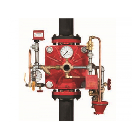
DV-5a Automatic Water Control Valve Deluge
Electric Actuation Fire Protection Systems
1 1/2 Inch to 8 Inch (DN40 to DN200)
General
Description
The TYCO DV-5
Automatic Water
a
Control Valve Deluge Electric Actua-
tion are diaphragm type valves that
can be used in deluge fire protection
systems. When properly trimmed, the
double seat design of the DV-5
also provides actuation of fire alarms
upon system operation.
The diaphragm style design of the
DV-5
Valve allows external resetting,
a
providing for easy resetting of a deluge
system without having to open a valve
handhole cover to manually reposition
a clapper and/or latch mechanism.
Simply re-pressurizing the diaphragm
chamber resets the valve.
The DV-5
features internal and exter-
a
nal coating of the valve to provide
corrosion resistance. The external cor-
rosion resistance of the epoxy coating
permits the use of the DV-5
rosive atmospheres associated with
many types of industrial processing
plants and outdoor installations.
The DV-5
Deluge Electric Actuation
a
Valve is offered with the DV-5
and separately ordered semi-assem-
bled trim as shown in Figure 5.
The DV-5
Deluge Electric Actua-
a
tion Valve is offered with or without a
System Main Control Valve.
NOTICE
The DV-5
Valves described herein
a
must be installed and maintained in
compliance with this document, as
well as with the applicable standards
of the NATIONAL FIRE PROTECTION
ASSOCIATION (NFPA), in addition to
the standards of any other authorities
having jurisdiction. Failure to do so
may impair the performance of these
devices.
IMPORTANT
Refer to Technical Data Sheet
TFP2300 for warnings pertaining to
regulatory and health information.
Page 1 of 18
Valve
a
in cor-
a
End Connection
Inlet
Outlet
Valve
a
Thread
Thread
Groove
Groove
Flange
Groove
Flange
Flange
The owner is responsible for main-
taining their fire protection system
and devices in proper operating con-
dition. Contact the installing contrac-
tor or product manufacturer with any
questions.
JUNE 2021
Worldwide
Available End Connections and Weights — lb/(kg)
Nominal Valve Size
1 1/2
2
3
(40)
(50)
(80)
26
25
N/A
(11,8)
(11,3)
25
25
60
(11,3)
(11,3)
(27,2)
66
N/A
N/A
(30,0)
72
N/A
N/A
(32,7)
www.tyco-fire.com
Contacts
ANSI Inches
(DN)
4
6
165,1
(100)
(150)
mm
N/A
N/A
N/A
95
177
177
(43,1)
(80,3)
(80,3)
106
190
N/A
(48,1)
(86,2)
116
204
N/A
(52,6)
(92,5)
TFP1321
8
(200)
N/A
327
(148,3)
346
(157,0)
365
(165,6)
Advertisement

Related Manuals for Tyco DN40


Summary of Contents for Tyco DN40
- Page 1 Worldwide www.tyco-fire.com Contacts DV-5a Automatic Water Control Valve Deluge Electric Actuation Fire Protection Systems 1 1/2 Inch to 8 Inch (DN40 to DN200) General Description The TYCO DV-5 Automatic Water Control Valve Deluge Electric Actua- tion are diaphragm type valves that can be used in deluge fire protection systems.
- Page 2 Hex Bolt, Short, Qty. 6 in 6 and 8 inch (DN150 and DN200) assemblies. Nut, Lift Washer or Hoist Ring with common hardware parts. b. Lift Washer not used in 1-1/2 and 2 inch (DN40 and DN50) assemblies. e. Also applicable to metric 165,1 mm size.
- Page 3 TFP1321 Page 3 of 18 Port Sizes, NPT Inch per ANSI B1.20.1 Port Port Description 1 1/2 (DN40) 2 (DN50) 3 (DN80) 4 (DN100) 6 (DN150) 8 (DN200) Diaphragm Chamber Supply Water Supply Pressure & Alarm Test Alarm Actuation Automatic Drain Valve...
-
Page 4: Technical Data
(260 mm) galvanized or black as required and Components for the 1 1/2 in. to 8 in. are malleable per ASME B16.3. (DN40 to DN200) DV-5 Valves are shown in Figure 1. The DV-5 Valves • Common hardware pipe nipples are 2 Inch (DN50) are for vertical installations. - Page 5 TFP1321 Page 5 of 18 FLOW RATE IN LITERS PER MINUTE (LPM) (1 GPM = 3,785 LPM) 1000 2000 3000 5000 7000 10000 15000 0,600 0,500 0,400 0,300 0,200 0,100 0,090 0,080 0,070 0,060 0,050 0,040 0,030 0,022 1000 2000 3000 4000 FLOW RATE IN GALLONS PER MINUTE (GPM)
- Page 6 TFP1321 Page 6 of 18 SYSTEM PIPING WITH OPEN NOZZLES OR SPRINKLERS - NORMALLY DRY ELECTRIC DETECTION SYSTEM (TYPICALLY 24 VOLTS DC) HEAT DETECTORS, SMOKE DETECTORS, MANUAL PULL STATIONS, ETC. SOLENOID DELUGE VALVE VALVE RELEASING PANEL (TYPICALLY (AUTOMATIC 24 VOLTS DC) CONTROL UNIT WITH BATTERY BACK-UP)
-
Page 7: Installation
40°F (4°C). that will not restrict flow. The TYCO DV-5 Valve Electric Actu- ation is to be installed in accordance Step 5. The Main Drain and Drip Funnel... - Page 8 Perform Steps 1 through 13 when ini- Step 10. Partially open the System type pilot sprinklers that were possibly tially setting the TYCO DV-5 Valve, exposed to a temperature greater than Main Control Valve (B). Slowly close the...
- Page 9 TFP1321 Page 9 of 18 Assemble in order 1-1/2" (DN40) AND 2" (DN50) from A to K VALVES ONLY NOTES 1. Port Connections P1 through P7 are described in Figure 2. 2. External Trim Connections C1 through C5 are described in Figure 18.
- Page 10 1 18 ordered. 5. V1 through V3 Water Column Prevention Drain Components are required for VdS and LPCB Approval. 1-1/2" (DN40) AND 2" (DN50) VALVES ONLY ITEM DESCRIPTION CH 1 1/2 IN. (DN40) 2 IN. (DN50) 3 IN. (DN80) 4 IN.
- Page 11 TFP1321 Page 11 of 18 ITEM DESCRIPTION CH 1-1/2 IN. (DN40) 2 IN. (DN50) 3 IN. (DN80) 4 IN. (DN100) 6 IN. (DN150) 8 IN. (DN200) PIPE NIPPLE 1/2" x 2" 1/2" x 2" 1/2" x 2" 1/2" x 2"...
- Page 12 TFP1321 Page 12 of 18 Nominal Inches Valve (mm) Size ANSI Inches (DN) 1 1/2 10.4 12.7 16.2 10.2 8.02 (40) (71) (246) (264) (323) (412) (185) (259) (204) (31) 10.4 12.7 16.2 10.2 8.09 (50) (71) (246) (264) (323) (412) (185) (259)
-
Page 13: Care And Maintenance
TFP1321 Page 13 of 18 Care and Drop in Water Supply Pressure Electric Actuation Below Normal Range Operation Test Procedure Maintenance Proper operation of the DV-5 Valve, NOTICE such as opening of the DV-5 Valve as during a fire condition, must be verified If the water supply pressure is signif- The following procedures and inspec- as follows:... - Page 14 TFP1321 Page 14 of 18 Item Description Item Description External Trim Connections DV-5 Valve Diaphragm Gauge Diaphragm Supply Connection System Main Control Valve System Gauge (Optional) Water Motor Alarm Connection Waterflow Pressure Switch Manual Control Station Waterflow Pressure Alarm Main Drain Valve Manual Reset Actuator Switch Connection System Drain Valve...
- Page 15 Step 1. With reference to Figure 1, problem. If there are no leaks, the Use only TYCO replacement fasteners ensure that the Diaphragm is properly DV-5 Valve is ready to be placed in as specified in Figure 1.
- Page 16 6 in. (DN150)....550130360 1 1/2 in. (DN40) ....530010015 8 in.
- Page 17 6 in. (DN150)....530050060 1 1/2 in. (DN40) ....530010015 Grooved x Grooved 8 in.
- Page 18 TFP1321 Page 18 of 18 1400 Pennbrook Parkway, Lansdale, PA 19446 | Telephone +1-215-362-0700 © 2021 Johnson Controls. All rights reserved. All specifications and other information shown were current as of document revision date and are subject to change without notice. NATIONAL FIRE PROTECTION ASSOCIATION and NFPA are registered trademarks of National Fire Protection Association;...
Need help?
Do you have a question about the DN40 and is the answer not in the manual?
Questions and answers