Table of Contents
Advertisement
Quick Links
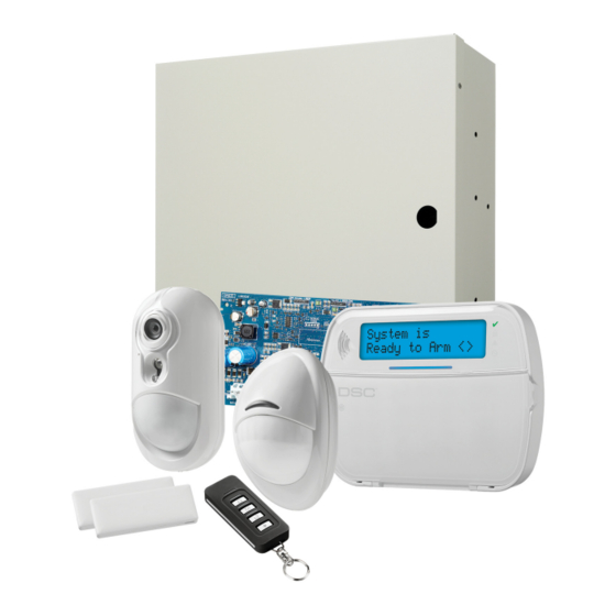
PowerSeries Neo Alarm Controller
WARNING: This manual contains information on limitations regarding product use and function and
information on the limitations as to liability of the manufacturer. The entire manual should be carefully
read.
V1.0 Reference Manual
firealarmresources.com
Models:
HS2016/HS2032/HS2064/HS2128
Advertisement
Table of Contents

Subscribe to Our Youtube Channel
Related Manuals for Tyco DSC PowerSeries HS2016


Summary of Contents for Tyco DSC PowerSeries HS2016
- Page 1 PowerSeries Neo Alarm Controller V1.0 Reference Manual Models: HS2016/HS2032/HS2064/HS2128 WARNING: This manual contains information on limitations regarding product use and function and information on the limitations as to liability of the manufacturer. The entire manual should be carefully read. firealarmresources.com...
-
Page 2: Table Of Contents
Contents 1: Introduction ....1 Factory Defaults ..........12 Alternate Communicator Setup... 12 About the System........1 Real Time Clock..........13 Features............. 1 Communication Paths ........ - Page 3 Contents DLS Programming.......... 24 Installer Programming ........25 Viewing Programming........25 Programming Hex and Decimal Data..... 25 Programming Descriptions....26 Adding Labels..........26 Zone Setup ............27 System Times..........30 Access Codes ..........30 PGM Configuration ........31 PGM Types ............. 31 System Options..........
- Page 4 Before Installing The Equipment Ensure your package includes the following items: • Installation and User manuals, including the SAFETY INSTRUCTIONS. READ and SAVE these instructions! Follow all WARNINGS AND INSTRUCTIONS specified within this document and/or on the equipment. • HS2016/2032/2064/2128 alarm controller •...
-
Page 5: 1: Introduction
S e c t i o n 1 : I n t r o d u c t i o n 1.1 About the System Model Differences The table below lists the features of each alarm system model. The PowerSeries Neo alarm panel is a feature-rich, scalable alarm system designed for residential and light commercial use. -
Page 6: Compatible Devices
S e c t i o n I n t r o d u c t i o n 1.1.3 Compatible Devices CO detector CO-12/24 The following wireless devices and modules are compatible with this 12-24SIR alarm controller. FW-CO12 FW-CO1224 NOTE: On the chart below and throughout this document, x in the CO1224 model number represents the operating frequency of the device as fol-... -
Page 7: 2: Installation
S e c t i o n 2 : I n s ta l l a t i o n 2.1 Overview of Installation Process 2.2.1 Mounting the Enclosure Locate the panel in a dry area, preferably near an unswitched AC The steps below are provided to assist with the installation of the power source and the incoming telephone line. -
Page 8: Wire Routing For Power & Non-Power Limited4
S e c t i o n I n s t a l l a t i o n 2.3.2 Wire Routing for Power & Non-Power Table 2-1: System Output Ratings Limited Device Output Rating (12V All wiring entry points are designated on the diagram by arrows. All HS2016 AUX: 700mA. -
Page 9: Installing Modules
S e c t i o n I n s t a l l a t i o n 2.4.2 Output Expander Line Loss Voltage loss through wire resistance must be considered for all instal- The HSM2208 module is used to add up to 8 low-current programmable lations. -
Page 10: Keypad Wiring
S e c t i o n I n s t a l l a t i o n 2.4.5 Keypad Wiring Diagram 2-8: PC5950 Wiring Diagram To wire a keypad to the alarm controller, remove the keypad back- B Universal Configuration Wiring Diagram plate (refer to the keypad installation sheet) and connect the R, B, Y, (Positive Bell Drive from Panel) and G terminals to the corresponding terminals on the alarm control-... -
Page 11: Pgm Wiring
S e c t i o n I n s t a l l a t i o n Normally Open and Normally Closed Diagram 2-11: DEOL Wiring Connect hardwired devices to any Z terminal and any Com terminal. Wire normally closed devices in series and normally open devices in parallel. -
Page 12: Telephone Line Wiring
S e c t i o n I n s t a l l a t i o n The Bell output is supervised and power limited by 2A PTC. If Table 2-9: Compatible 2-Wire Smoke Detectors unused, connect a 1000 resistor across Bell+ and Bell- to prevent FSA-210B FSA-210BLST FSA-210BRST... -
Page 13: Ground Wiring
S e c t i o n I n s t a l l a t i o n 2.4.14 Ground Wiring NOTE: Using an insulated green wire (minimum 22AWG), connect the EGND terminal on the Corbus and the grounding wire from the building electrical installation to any of the available holes on the back or side of the metal cabinet. -
Page 14: 3: Configuration
S e c t i o n 3 : C o n f i g u r a t i o n 3.1 Basic Configuration Steps 4 flashes - battery trouble 5 flashes - AC trouble Once basic installation of the alarm panel is complete, the following 6 flashes - AUX trouble general configuration options should be set: 7 flashes - bell trouble... -
Page 15: Module Supervision
S e c t i o n C o n f i g u r a t i o n Pre-Enrollment Table 3-1 Module Capacity Pre-enrollment is a two step process. The first step requires entering Module HS2016 HS2032 HS2064 HS2128 each device ID ([804][001]-[716]). -
Page 16: Trouble Indicators
S e c t i o n C o n f i g u r a t i o n 3.6.3 Bell/PGM Support NOTE: Only the first output of the HSM2204 output module has bell supervision. Some conditions, such as an installer system test, may over- PGMs must be assigned to one, some or all partitions. -
Page 17: Real Time Clock
S e c t i o n C o n f i g u r a t i o n 3.8 Local Firmware Upgrade Refer to the 3G2080(R)/ TL2803G(R)/ TL280(R) installation manual for details. Alarm panel firmware can be upgraded locally via DLS. Firmware upgrade prevention rules are ignored when performing a local firm- 3.7.1 Real Time Clock ware upgrade. -
Page 18: 4: System Operation
S e c t i o n 4 : S y s t e m O p e r a t i o n 4.1 Arming and Disarming In the following example, partition 1 is armed, partition 2 is dis- armed and ready, partition 3 is disarmed and not ready, partition The following table describes the various arming and disarming 4 is in alarm, and partitions 4-8 are not enabled. -
Page 19: Event Labels
S e c t i o n S y s t e m O p e r a t i o n 4.3.5 Event Labels To program a function key: Enter Installer Programming [*][8]. Customizable labels can be created for the following events: Enter section [861] for function key programming. -
Page 20: Language Selection
S e c t i o n S y s t e m O p e r a t i o n [13] Global Away Arm [37] Time & Date Program This function arms all partitions assigned to the user in Away mode, This function places the keypad in date/time programming mode. -
Page 21: Bypass Or Stay/Away/Night Zones
S e c t i o n S y s t e m O p e r a t i o n 4.7.1 [*][1] Bypass or Stay/Away/Night Bypass Recall Zones Press [*] while in this menu to bypass the same group of zones that were bypassed the last time the partition was armed. -
Page 22: Alarm Memory Display
S e c t i o n S y s t e m O p e r a t i o n Trouble 02 – Module Battery Trouble: Trouble 08 – RF Delinquency Trouble: [01] Panel Low Battery Trouble: The battery voltage (under load) is [01] Zone 001 - 128 RF Delinquency: No response from a wireless below 11.5V. -
Page 23: Door Chime Enable/Disable
S e c t i o n S y s t e m O p e r a t i o n This feature can be programmed to require an access code. See sec- tion. This code can be programed by the installer in section tion [023] option 6 for details. - Page 24 S e c t i o n S y s t e m O p e r a t i o n Press [1] to select access code. Using an LCD keypad: Press [*][5] then select a user (02-95). Key in a new access code. On the “Press [*] for User Labels”...
-
Page 25: User Functions
S e c t i o n S y s t e m O p e r a t i o n 4.7.6 [*][6] User Functions • AC / DC Inhibit Arm • Latching System Tampers The [*][6] command provides access to functions described below. If •... -
Page 26: Command Outputs 1-4
S e c t i o n S y s t e m O p e r a t i o n Keypad: [*][6][master code] + 12 the panel without an entry delay on delay type zones and bypasses stay/away and night type zones. This function is used to change the brightness level of keypad display backlighting. -
Page 27: Visual Verification
S e c t i o n S y s t e m O p e r a t i o n 4.9 Visual Verification This feature enables the central station operator to view captured images of the premises in the event of an alarm event. Combination camera/motion detectors can be installed throughout the premises to provide visual verification coverage. -
Page 28: 5: Programming
S e c t i o n P r o g r a m m i n g S e c t i o n 5 : P r o g r a m m i n g 5.1 How to Program does not save the changed data. -
Page 29: Installer Programming
S e c t i o n P r o g r a m m i n g 5.2.3 Installer Programming For sections that require multiple two or three-digit numbers, the keypad beeps three times after each entry and moves to the next item Installer Programming is used to manually program alarm system on the list. -
Page 30: Programming Descriptions
S e c t i o n P r o g r a m m i n g Example: For the 4-digit account number ‘4032’, enter [4] [*] [1] [*] If any key other than [<] or [>] is pressed before [0], the cursor [3], [0]. -
Page 31: Zone Setup
S e c t i o n P r o g r a m m i n g [051] Zone Tamper Label [806] HSM2HOSTx Label This label is displayed when a zone is tampered. The maximum label Use this section to create a custom label for the 2-way wireless trans- size is 14 x 1 ASCII characters. - Page 32 S e c t i o n P r o g r a m m i n g Interior Stay/Away Auto Verify Fire – – Similar to Interior zone type except that the system bypasses the zone (Hardwired smoke detectors) when armed in Stay mode.
- Page 33 S e c t i o n P r o g r a m m i n g 24 Hour High Temperature Doorbell Zone – – This zone type is used with temperature sensors and is activated This zone type sounds a chime through keypads on the partition when the temperature rises above a programmed threshold (set in when activated.
-
Page 34: System Times
S e c t i o n P r o g r a m m i n g Single End of Line (SEOL) Resistors NOTE: For UL installations, the Entry Delay plus the Communica- – tions Delay must not exceed 60 seconds. ON: The zone requires a single end-of-line resistor (5.6K). -
Page 35: Pgm Configuration
S e c t i o n P r o g r a m m i n g 5.3.5 PGM Configuration • Bell squawk conditions • Audible exit fault This section describes how to set up and configure programmable This output activates when the alarm output is active and turns off outputs. - Page 36 S e c t i o n P r o g r a m m i n g 115 – System Armed Status resistor is required for this input (to Aux+). If a short or open occurs, an alarm is generated for all partitions and sirens. PGM partition This output activates when all selected partitions are armed (end of assignment does not affect this PGM type.
- Page 37 S e c t i o n P r o g r a m m i n g • Not Networked 176 – Remote Operation This output deactivates when all of the selected trouble conditions This output is activated and deactivated remotely on command from are cleared.
- Page 38 S e c t i o n P r o g r a m m i n g 115 – Armed Status • Bell Squawk on Exit (single every second) • Bell Squawk on Entry (single every second) 01 – True output/Inverted •...
- Page 39 S e c t i o n P r o g r a m m i n g • repeater 01 – 08 fault ON: activates with fire alarm, [F] key, fire zones, 2-wire smoke. OFF: does not activate with fire alarm. •...
- Page 40 S e c t i o n P r o g r a m m i n g ON: deactivated during normal operation. Activated when • Receiver 1 – 4 absent triggered. • Receiver 1 – 4 supervision trouble OFF: activated during normal operation. Deactivated when •...
-
Page 41: System Options
S e c t i o n P r o g r a m m i n g OFF: zones are not enabled for zone follower operation. NOTE: The valid EOL value is 5600 Ohms (5.6K). 2 – DEOL/SEOL [011] PGM Configuration Options ON: All zones use Double-End-of-Line resistors, except Standard Fire, Delayed Fire, Auto-Verified Fire, Co and Supervisory zone This section is used to configure PGM types that offer multiple... - Page 42 S e c t i o n P r o g r a m m i n g NOTE: Fire, Medical, and Panic key transmissions follow the parti- [014] System Option 2 tion 1 alarm/restore call direction options (Fire, Medical, and Panic key).
- Page 43 S e c t i o n P r o g r a m m i n g 3 – Keypad Blanking logged and transmitted. The number of zone trips required to create a confirmed alarm depends on the value of the programmable burglary ON: If no keys are pressed for 30 seconds, all keypad lights except verification counter.
- Page 44 S e c t i o n P r o g r a m m i n g open zones, bypass recall as well as other methods such as bypassing [021] System Option 9 via ITv2 or DLS. Global Zones: 24-hour zone bypasses are logged and communicated 1 –...
- Page 45 S e c t i o n P r o g r a m m i n g steadily. If a non-force arm capable zone is tripped, the ready LED 5 – Real-Time Clock turns off. ON: The alarm system sends a real-time clock request to the alternate OFF: If a force arm capable zone is tripped, the Ready LED is illumi- communicator at 4:05pm or when system time is lost.
-
Page 46: Partition Setup
S e c t i o n P r o g r a m m i n g OFF: If a Failure to Communicate trouble is generated while the week from Sunday to Saturday. Time is in 24-hour format (HH:MM) alarm system is armed, the siren does not activate but the keypad and valid entries are from 00:00 to 23:59. -
Page 47: Reporting
S e c t i o n P r o g r a m m i n g The number of available partitions depends on the model, as shown [05] Alternate Communicator Receiver 3 below: Events are communicated through cellular receiver 1. Model Zones Partitions... - Page 48 S e c t i o n P r o g r a m m i n g [001] Miscellaneous Alarm 1 [101] Tamper Events The reporting codes in this section are sent to the Alarm & Restore 3/4 – Module Tamper/Restore call direction group.
- Page 49 S e c t i o n P r o g r a m m i n g [301] Panel Events 1 When the Delinquency option is on, this code is transmitted when no zone activity has been detected on the system for the number of hours 1/2 –...
-
Page 50: System Communications
S e c t i o n P r o g r a m m i n g [355] Alternate Communicator 5 3/4 – Module Battery Trouble/Restore These reporting codes are transmitted when a module’s battery volt- Receiver 1 to 4 Supervision Failure and Restore age falls below 11.5VDC or is restored. - Page 51 S e c t i o n P r o g r a m m i n g [04] Receiver 4 [309] System Call Direction [002] Tampers (Including System Tampers)/ Restore Use this programming option to select the central station receivers These options control which receiver paths are enabled for Partition that system events are communicated to.
- Page 52 S e c t i o n P r o g r a m m i n g [002] – Communication Delays Valid entries are from 00 to 23 for the hours (HH) and 00 to 59 for the minutes (MM). Transmission Delay (seconds) To disable the test transmission time of day, enter [9999] in this sec- This value defines the delay before an alarm is transmitted.
- Page 53 S e c t i o n P r o g r a m m i n g 3 – Pulse Dialing again until the partition has been armed. Each day programmed in the counter represents one day plus the time it takes for the partition to ON: The alarm system dials telephone numbers using pulse (rotary) reach midnight.
-
Page 54: Dls Programming
S e c t i o n P r o g r a m m i n g 5 – Alternate Communicator Enable/Disable 4 – Receiver 4 Backup Option ON: The system communicates using the alternate communicator. ON: Receiver 4 backs up Receiver 3. Receiver 4 is only used if an All related programming options, reporting and supervision are FTC event is detected on Receiver 3. - Page 55 S e c t i o n P r o g r a m m i n g 4 – User Call-Up [406] PSTN Number of Rings to Answer On ON: A single call attempt can be made to the downloading computer using [*][6][Master Code][06].
-
Page 56: Schedule Programming
S e c t i o n P r o g r a m m i n g 5.3.13 Wireless Programming [003] Periodic DLS Time This section is used to program the time of day periodic DLS down- load takes place. Time is in 24-hour format and the default is 00:00 [804] Wireless Programming (midnight). -
Page 57: Systems Information
S e c t i o n P r o g r a m m i n g • Digit 2 - system EOL options • 8-output expander module (HSM2208) • Digit 3 - alarm controller communications options • Power supply (HSM2300) •... -
Page 58: Testing
S e c t i o n P r o g r a m m i n g [903] Confirm Module [982] Battery Settings The following sections are used to confirm enrollment of individual [000] – Panel Battery Settings modules, their serial and slot numbers, and to locate them physically: 01 –... -
Page 59: 6: Programming Worksheets
S e c t i o n 6 : P r o g r a m m i n g Wo r k s h e e ts This section provides a detailed list of all available programming options and a place to record custom settings. The index below lists all available programming sections in numerical order and includes page references to description and worksheet locations. - Page 60 001 – Automatic DLS Toggle Options ..... 51/85 03 – Burglary Verification Selection ......42/73 002 – Periodic DLS Days ......... 51/85 151-158 Partition 1-8 Auto-Arm/Disarm ......42/74 003 – Periodic DLS Time ......... 52/85 001 – Auto-Arming Times ........42/74 007 – Delay Call Window ........52/85 002 –...
- Page 61 S e c t i o n P r o g r a m m i n g W o r k s h e e t s Label Programming [000] Label Programming Description on page 26 000 – Language Selection (2-digit decimal;...
- Page 62 S e c t i o n P r o g r a m m i n g W o r k s h e e t s [000] 051 – Zone Tamper Label (1 x 14 Characters): 052 – Zone Fault Label (1 x 14 Characters): 064 –...
- Page 63 S e c t i o n P r o g r a m m i n g W o r k s h e e t s [000] 801 – Keypad Labels (1 X 14 ASCII) Description on page 27 001 –...
- Page 64 S e c t i o n P r o g r a m m i n g W o r k s h e e t s 006– Repeater 6 Label: 007– Repeater 7 Label: 008– Repeater 8 Label: [000] 999 –...
- Page 65 S e c t i o n P r o g r a m m i n g W o r k s h e e t s Zone Attribute Defaults (Description on page 29) Zone Attributes Zone Type 000 Null Zone 001 Delay 1 ...
- Page 66 S e c t i o n P r o g r a m m i n g W o r k s h e e t s System Times [005] System Times 000 – System Area Bell Cutoff (Default: 004): (3-Digit Decimal) Description on page 30 Burglary Verification Timer (Default: 060):...
- Page 67 S e c t i o n P r o g r a m m i n g W o r k s h e e t s Access Codes 006 Installer-Defined Codes 001 – Installer Code (Default:555555): (4/6-Digit Decimal) 002 –...
- Page 68 S e c t i o n P r o g r a m m i n g W o r k s h e e t s 001 – PGM Partition Partition Partition Partition Partition 053: 1 2 3 4 5 6 7 8 081: 1 2 3 4 5 6 7 8 109: 1 2 3 4 5 6 7 8 137: 1 2 3 4 5 6 7 8...
- Page 69 S e c t i o n P r o g r a m m i n g W o r k s h e e t s [008] PGM Timer 000 – PGM Timers Minutes or Seconds: Minutes Seconds Programming (3-Digit Decimal) 001 –...
- Page 70 S e c t i o n P r o g r a m m i n g W o r k s h e e t s [009] PGM Types 114 – Ready To Arm 132 – Holdup Output 175 –...
- Page 71 S e c t i o n P r o g r a m m i n g W o r k s h e e t s [010] PGM Attributes Partition 1 Mask 000 – Main Bell Mask ...
- Page 72 S e c t i o n P r o g r a m m i n g W o r k s h e e t s [010] 184 – Open After Alarm 01 – True Output PGM Timer ...
- Page 73 S e c t i o n P r o g r a m m i n g W o r k s h e e t s [010] PGM Attribute Assignment: (3-Digit Decimal) 001 – PGM 1: 042 – PGM 42: 083 –...
- Page 74 S e c t i o n P r o g r a m m i n g W o r k s h e e t s [011] PGM Config. Options (4-Digit Decimal) Valid Range: 000-028 Description on page 37 Zone Follower by Zone Prox.
- Page 75 S e c t i o n P r o g r a m m i n g W o r k s h e e t s Zone Follower by Zone Prox. Used Command Output (001-128; Default 000) (000-095; Default 000) (001-004;...
- Page 76 S e c t i o n P r o g r a m m i n g W o r k s h e e t s Zone Follower by Zone Prox. Used Command Output (001-128; Default 000) (000-095; Default 000) (001-004;...
- Page 77 S e c t i o n P r o g r a m m i n g W o r k s h e e t s System Lockout [012] System Lockout (3-Digit Decimal) Keypad Lockout: (Range: 000-255; Default 000) Keypad Lockout Duration: (Range: 001-255;...
- Page 78 S e c t i o n P r o g r a m m i n g W o r k s h e e t s [041] Access Code Digits 00 – 4-Digit Access Codes Description on page 42 ...
- Page 79 S e c t i o n P r o g r a m m i n g W o r k s h e e t s 002 – Partition 3 Auto-Disarm Times: 24-Hour: Sunday: Thursday: (4-digit HH:MM) Monday: Friday: Default: 9999 Tuesday:...
- Page 80 S e c t i o n P r o g r a m m i n g W o r k s h e e t s 006 – Partition 5 No Activity Arming Timer (Default: 000): 007 – Partition 5 No Activity Arming Pre-Alert Timer (Default: 001): [156] Partition 6 Auto-Arm/ 001 –...
- Page 81 S e c t i o n P r o g r a m m i n g W o r k s h e e t s 002 – Partition 8 Auto-Disarm Times: 24-Hour: Sunday: Thursday: (4-digit HH:MM) Monday: Friday: Default: 9999 Tuesday:...
- Page 82 S e c t i o n P r o g r a m m i n g W o r k s h e e t s [204] Partition 4 Zone Assignment [205] Partition 5 Zone Assignment [206] Partition 6 Zone Assignment 2 3 4 5 6 7 8 2 3 4 5 6 7 8 2 3 4 5 6 7 8...
- Page 83 S e c t i o n P r o g r a m m i n g W o r k s h e e t s [300] Panel/Receiver Communications Path Description on page 43 001 – Receiver 1: ...
- Page 84 S e c t i o n P r o g r a m m i n g W o r k s h e e t s [307] Zone Reporting Description on page 43 (001-128 = zones 1-128) 1 – Alarm ...
- Page 85 S e c t i o n P r o g r a m m i n g W o r k s h e e t s [308] Event Reporting Description on page 43 001 – Miscellaneous 1 – Duress Alarm 002 –...
- Page 86 S e c t i o n P r o g r a m m i n g W o r k s h e e t s 351 – Alternate 1 – Alt. Comm. Module Comm Fault 352 – Alternate ...
- Page 87 S e c t i o n P r o g r a m m i n g W o r k s h e e t s [312] Partition 2 Call Directions 001 – Partition 2 Alarm/ Restore: Receiver #1 ...
- Page 88 S e c t i o n P r o g r a m m i n g W o r k s h e e t s [350] Communicator Formats Description on page 47 (2-Digit decimal) 001 – Receiver 1: 003 –...
- Page 89 S e c t i o n P r o g r a m m i n g W o r k s h e e t s DLS Programming [401] DLS/SA Options 1 – Double Call 4 – User Call up Description on page 50 2 –...
- Page 90 S e c t i o n P r o g r a m m i n g W o r k s h e e t s Interval 3 301 – Start Time: 302 – End Time: 303 – Days Assignment: 304 –...
- Page 91 S e c t i o n P r o g r a m m i n g W o r k s h e e t s [603] Programming Schedule 3 Interval 1 101 – Start Time: 102 – End Time: 103 –...
- Page 92 S e c t i o n P r o g r a m m i n g W o r k s h e e t s Interval 2 201 – Start Time: 202 – End Time: 203 – Days Assignment: 204 –...
- Page 93 S e c t i o n P r o g r a m m i n g W o r k s h e e t s [713] Holiday Group 3 (6-Digit Decimal) 001 – Holiday Group 1 Date 1: MMDDYY 002 –...
- Page 94 S e c t i o n P r o g r a m m i n g W o r k s h e e t s [861]-[876] Keypad Programming Refer to the installation instructions provided with the keypad for details. 000 –...
- Page 95 S e c t i o n P r o g r a m m i n g W o r k s h e e t s Door Chime Zone Assignment: 1 ____ 13 ____ 25 ____ 37 ____ 49 ____ 61 ____ 73 ____ 85 ____ 97 ____ 109 ____ 121 ____ 2 ____ 14 ____ 26 ____ 38 ____ 50...
- Page 96 S e c t i o n P r o g r a m m i n g W o r k s h e e t s [903] Confirm Modules 000 – View All Modules Description on page 54 001 –...
-
Page 97: 7: Troubleshooting
S e c t i o n 7 : Tro u b l e s h o o t i n g 7.1 Testing • Power up system • Program options as required (See “Programming Descriptions” on page 26). • Trip, then restore zones •... - Page 98 S e c t i o n T r o u b l e s h o o t i n g Trouble [1] Service Required Press [01] to determine specific trouble Trouble Troubleshooting [01] Bell Circuit • Disconnect Bell-/+ leads and measure resistance: Bell+, Bell-...open circuit.
- Page 99 S e c t i o n T r o u b l e s h o o t i n g Trouble [3] Bus Voltage Trouble Press [03] to determine specific trouble Trouble Troubleshooting [01] HSM2HOST Bus Low Voltage •...
- Page 100 S e c t i o n T r o u b l e s h o o t i n g Trouble [6] Device Low Battery Press [06] to toggle through specific devices with low battery trouble Trouble Troubleshooting [01] Zones 1-128 •...
- Page 101 S e c t i o n T r o u b l e s h o o t i n g Trouble [11] Communications Press [11] to determine specific trouble Trouble Troubleshooting [01] Phone Line Trouble • Measure the voltage across TIP and RING on the panel: Phone line voltage at TIP, RING on main panel less than •...
-
Page 102: Appendix A : Event Codes
A p p e n d i x A : E v e n t C o d e s The following tables contain Contact ID and Automatic SIA format reporting codes. See Programming Sections [308] for event reporting codes. Contact ID Each of the digits indicate specific information about the signal. - Page 103 Automatic Dialer SIA Auto Section # Definition Contact ID Direction* Rep Codes** Codes [308]-[101] Siren 14 tamper/restore alarm (3)83-814 TA-0814/TR-0814 [308]-[101] Siren 15 tamper/restore alarm (3)83-815 TA-0815/TR-0815 [308]-[101] Siren 16 tamper/restore alarm (3)83-816 TA-0816/TR-0816 [308]-[101] Repeater 1 tamper/restore alarm (3)83-901 TA-0901/TR-0901 [308]-[101] Repeater 2 tamper/restore alarm (3)83-902...
- Page 104 Automatic Dialer SIA Auto Section # Definition Contact ID Direction* Rep Codes** Codes Opening Events [308]-[201] User Openings - Disarmed by user (4)A1-UUU OP-UUUU [308]-[202] Automatic Arming Canceled (4)55-000 CI-0000 [308]-[201] Special Opening - System disarmed using: keyswitch, maintenance code, DLS (4)AA-000 OP-0000 software, wireless key...
- Page 105 Automatic Dialer SIA Auto Section # Definition Contact ID Direction* Rep Codes** Codes [308]-[332] HSM2300 Aux Supply 1 trouble/restore MA/R (3)12-621 YI-0621/YJ-0621 [308]-[332] HSM2300 Aux Supply 2 trouble/restore MA/R (3)12-622 YI-0622/YJ-0622 [308]-[332] HSM2300 Aux Supply 3 trouble/restore MA/R (3)12-623 YI-0623/YJ-0623 [308]-[332] HSM2300 Aux Supply 4 trouble/restore MA/R (3)12-624...
- Page 106 Automatic Dialer SIA Auto Section # Definition Contact ID Direction* Rep Codes** Codes [308]-[361] Repeater 5 AC fail/restore MA/R (3)A1-905 AT-0905/AR-0905 [308]-[361] Repeater 6 AC fail/restore MA/R (3)A1-906 AT-0906/AR-0906 [308]-[361] Repeater 7 AC fail/restore MA/R (3)A1-907 AT-0907/AR-0907 [308]-[361] Repeater 8 AC fail/restore MA/R (3)A1-908 AT-0908/AR-0908...
- Page 107 Contact ID SIA Zone Alarm/Restore Event Codes (as per SIA DCS: ‘Contact ID’ 01-1999): The table below defines the meaning of all contact ID alarm/restore event codes. Table A-1 Contact ID Event Codes Zone Definition SIA Auto Rep Contact ID Auto Codes Rep Codes Delay 1...
-
Page 108: Appendix B : Word Library
A p p e n d i x B : Wo r d L i b r a r y Item # Text Item # Text Item # Text Item # Text Item # Text Item # Text 001 Aborted 042 Control 083 Garage 124 Motion... -
Page 109: Tables
A p p e n d i x C : Te m p l a t e P r o g r a m m i n g Tab l e s The following tables show the programming options for template programming digits 1-5. •... - Page 110 Receiver 1 SIA [380] Comm Toggles 1 - Bit 1 Communications Enabled - On [350] Communicator Formats - [001] Receiver 1 - 04 SIA [350] Communicator Formats - [002] Receiver 2 - 04 SIA [350] Communicator Formats - [003] Receiver 3 - 04 SIA [350] Communicator Formats - [004] Receiver 4 - 04 SIA [381] Comm Toggles 2 - Bit 2 Bell Ringback - Off [384] Comm Backup - Bit 2 Receiver 2 Backup - Off...
- Page 111 • Common Group – Enables/Disables all Reporting Codes Common Group Common Group Programming Set all reporting codes to automatic [308] Event Reporting - All Events On Alarm/restore call directions enabled [311][001] Partition 1 Alarm/Restore - Bit 1 Receiver 1 - On [311][001] Partition 1 Alarm/Restore - Bit 2 Receiver 2 - Off [311][001] Partition 1 Alarm/Restore - Bit 3 Receiver 3 - Off [311][001] Partition 1 Alarm/Restore - Bit 4 Receiver 4 - Off...
- Page 112 • Openings & Closings - Sets Residential Dial Reporting Codes for all openings and closings Openings/Closings Group Openings/Closings Programming Enable All User Open/Close Reports [308][201] - Bit 1 User Closing - On [308][201] - Bit 2 User Opening - On [308][201] - Bit 3 Partition Closing - Off [308][201] - Bit 4 Partition Opening - Off [308][201] - Bit 5 Special Closing - On...
- Page 113 Program the required DLS access code. All 6 digits must be entered in order to complete your entry. This access code is entered into programming section [453]. Entry Delay 1 and Exit Delay Enter the 3-digit entry delay 1 (in seconds) followed by the desired 3-digit exit delay (in seconds). These entries affect all partitions. All 3 digits must be entered in order to complete each section entry.
-
Page 114: Appendix D : Regulatory Approvals
A p p e n d i x D : R e g u l a t o r y A p p r o v a l s FCC COMPLIANCE STATEMENT Alarm dialling equipment must be able to seize the telephone line and place a call in an emergency situation. -
Page 115: Ul/Ulc Installations
4.0.1 UL/ULC Installations • The bell timeout shall be programmed for 15 minutes minimum • At least one system remote keypad with tamper switch shall be employed This product has been tested and found in compliance with the following stan- •... - Page 116 Aux Loading and Battery Selection HS2128/HS2064/HS2032/HS2016 UL Resi Burg UL Com Burg UL Resi Fire ULC Fire Monitoring EN50131 Board current draw mA ULC Resi Burg UL Home Health Care Grade 2/Class II ULC Resi Fire ULC Com Burg 0.7A 0.7A 0.5A 0.5A...
-
Page 117: Sia False Alarm Reduction Installations: Quick Reference
4.0.2 SIA False Alarm Reduction Installations: Quick Reference Minimum required system consists of one Control unit model HS2128 or HS2064 or HS2032 or HS2016 and any one of the compatible listed keypads: HS2LCDRF9, HS2LC- DRFP9, HS2ICNRF9, HS2ICNRFP9, HS2LCD, HS2LCDP, HS2ICN, HS2ICNP, HS2LED. The following wireless keys can also be used in SIA compatible installations: PG9929, PG9939,PG9949. -
Page 118: Appendix E : Ascii Characters
A p p e n d i x E : A S C I I C h a r a c t e r s “ & ‘ 33 34 35 36 37 38 39 40 41 42 43 44 45 46 47 48 49 50 51 52 53 54 55 56 <... -
Page 119: Appendix F : Wiring Diagrams
A p p e n d i x F : W i r i n g D i a g r a m s HS2016, HS2032, HS2064, HS2128 UL/ULC Wiring Diagram HS2016/2032/2064/2128 UL/ULC Wiring Diagram *AUX Wiring Use No.14-22 AWG conductor AUX+ and Keybus (RED) are internally connected. - Page 120 HS2016/032/064/128 Standard Wiring Diagram For NA North America Only POWER LIMITED Stand Of f PC Boar d Cable Tie (not supplied) recommended Cabinet UA 503 HS2016/032/064/128 WARNING: High Voltage . Disconnect AC Power and telephone lines before servicing HS2016-4 HS2016-4 HS2032 HS2064 HS2064...
- Page 121 Zone Wiring Zones can be wired for Normally Open, Normally Closed Con- tacts with Single-end-of-line (SEOL) resistors or Double End- Normally Closed Loops - Do NOT use for UL Installations of-Line (DEOL) resistors. Observe the following guidelines For UL Listed Installations use SEOL or DEOL only. Minimum 22 AWG wire, maximum 18 AWG Do NOT use shielded wire ...
- Page 122 PGM Wiring PGMs switch to ground when activated by control panel. PGM 1, LED Output with current limiting resistor and Optional Connect the positive side of the device to be activated to the AUX+ Relay driver output Terminal. Connect the negative terminal to the PGM. current output is as follows •...
-
Page 123: Appendix G : Specifications
A p p e n d i x G : Spe c i f i c a t i o n s Zone Configuration • 4Ah (PS4-12) • 16, 32, 64, or 128 wireless zones supported and 8 hardwired zones •... - Page 124 Guidelines for Locating Smoke & CO Detectors The following information is for general guidance only and it is recommended that local fire codes and regulations be consulted when locating and installing smoke and CO alarms. Smoke Detectors Research indicates that all hostile fires in homes generate smoke to a greater or lesser extent. Detectable quantities of smoke precede detectable levels of heat in most cases.
- Page 125 SOFTWARE PRODUCT), the accompanying printed materials, and any copies of the and any related Hardware) and Digital Security Controls, a division of Tyco Safety Products Canada Ltd. (“DSC”), the manufacturer of the SOFTWARE PRODUCT, are owned by DSC or its suppliers. You may not copy the printed materials accompanying the SOFTWARE integrated security systems and the developer of the software and any related products or components (“HARDWARE”) which You acquired.
-
Page 126: Appendix H : Index
I n d e x Symbols Alt. Comm Battery Trouble/Restore Bell Squawk On Trouble Option Alt. Comm Communications Fault/Restore Bell Squawk Option Alt. Comm Ethernet Trouble /Restore Bell Status and Programming Access Output Access Code Required for Alt. Comm Lockout Trouble/Restore Bell Timeout Sensor Reset Alt. - Page 127 Control Panel Information Event Buffer Installer Lead In and Lead Out Control Panel Installation Event Buffer 75% Full Installer Lockout Controls and Indicators Event Buffer Swinger Installer Programming Corbus Wiring Event Buffers, Viewing Installer Walk Test Courtesy Pulse Event Labels Installer Walk Test Enable/Disable Crystal Timebase Event Reporting...
- Page 128 Partition 1-8 Timer Partition Account Codes Maid’s Code Attribute Ready LED Flashes for Force Arming Partition Auto-Arm Postpone Timer Main Bell Mask Ready to Arm Partition Auto-Arm/ Disarm Main Bell Operational Mask Real Time Clock Partition Auto-Arm/Disarm Maintain Arm Real Time Clock Option Partition Auto-Arming Pre-Alert Ti mer Maintain Disarm Real-Time Redundant Communications...
- Page 129 System Account Code System Area Verified Events System Armed Status Video Verification System Call Direction Viewing Event Buffers System Information Viewing Programming System Label Voice Chime System Labels System Lockout System Option 1 System Option 10 Walk Test System Option 11 Walk Test Communications System Option 12 Walk Test Start &...
- Page 130 Tyco International Ltd. will aggressively enforce its intellectual property rights to the fullest extent of the law, including pursuit of criminal prosecution wher- ever necessary. All trademarks not owned by Tyco International Ltd. are the property of their respective owners, and are used with permission or allowed under applicable laws.
Need help?
Do you have a question about the DSC PowerSeries HS2016 and is the answer not in the manual?
Questions and answers