Otto Bock Motus CV Instructions For Use Manual
Hide thumbs
Also See for Motus CV:
- Instructions for use manual (80 pages) ,
- Instructions for use manual (68 pages) ,
- Instructions for use manual (36 pages)

Related Manuals for Otto Bock Motus CV


Summary of Contents for Otto Bock Motus CV
- Page 1 Motus CV, Motus CS Instructions for use (user) ..................
- Page 2 Motus CV, Motus CS...
-
Page 3: Table Of Contents
7.7.2 Removing the push handles ........................7.7.3 Folding the push handles ........................Stabiliser bar ............................Drive wheels ............................7.9.1 Removing and mounting the drive wheels ....................7.9.2 Rear wheel with one-handed operation (double push rings) ..............Motus CV, Motus CS... - Page 4 Inner tube, rim tape and tyre replacement ....................Disposal ................................Disposal information ..........................Legal information .............................. 10.1 Liability .............................. 10.2 Warranty ............................10.3 Lifetime .............................. Technical data ..............................Appendices ................................ 12.1 Threshold values for wheelchairs transportable by train ................Motus CV, Motus CS...
-
Page 5: Foreword
Your product may differ from the models shown. In particular, not all the options described in these instruc tions for use will be installed on your product. • The manufacturer reserves the right to make technical changes to the model described in these instructions for use. Motus CV, Motus CS... -
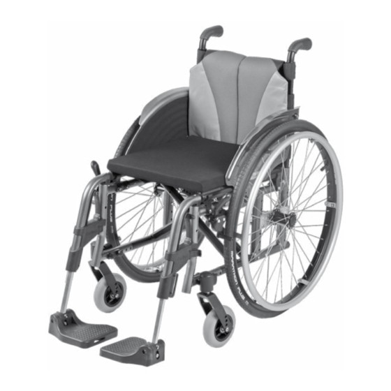
Page 6: Product Description
11 Quick-release axle 4 Knee lever wheel lock 12 Rear frame 5 Front frame 13 Back support tube 6 Crossbrace 14 Back support, back support upholstery 7 Foot plate (segmented) 15 Push handle 8 Caster fork Motus CV, Motus CS... - Page 7 9 Drive wheel with handrim 3 Scissor wheel lock 10 Quick-release axle 4 Front frame 11 Rear frame 5 Crossbrace 12 Back support tube 6 Foot plate (single-panel) 13 Back support, back support upholstery 7 Caster fork 14 Push handle Motus CV, Motus CS...
-
Page 8: Intended Use
► In case of problems with the settings, please contact the qualified personnel who adjusted your product. WARNING Improper handling of packaging materials Risk of suffocation due to neglect of the duty to supervise ► Packaging materials must be kept out of the reach of children. Motus CV, Motus CS... - Page 9 ► Never cross obstacles at an angle. Always approach obstacles head on (at an angle of 90°). ► Raise the front wheels before crossing obstacles. ► Avoid collisions with obstacles and dropping off curbs/ledges. ► Avoid riding cross-country. Motus CV, Motus CS...
- Page 10 Hypothermia or burns due to contact with components, failure of components ► Do not expose the product to any extreme temperatures (e.g. direct sunlight, sauna, extreme cold). ► Do not leave the product in the immediate vicinity of heaters. Motus CV, Motus CS...
-
Page 11: Side Effects
Even in the event of compliance with all applicable guidelines and standards, alarm systems (e.g. in department stores) may respond to your product. Should this happen, remove your product from the area where the alarm was triggered. Motus CV, Motus CS... -
Page 12: Nameplate And Warning Labels
The product should always be stored so it is protected against external influences. 5.3.2 Storage during extended disuse The product must be stored in a dry place. Specific information for extended storage: see page 46. It is not necessary to disassemble the product. Motus CV, Motus CS... -
Page 13: Preparing The Product For Use
6) Fold down the foot plates. With a single-panel foot plate, make sure the foot plate support is locked into the mounting (see fig. 7). 7) Fit the seat cushion (see fig. 8). The seat cushion is secured against sliding by being pressed onto the hook- and-loop closure. Motus CV, Motus CS... -
Page 14: Use
As a rule, the frame tubes, seat bottom or side panels can be used as supports for getting into the wheelchair. If getting in independently is not possible, transferring or getting in always has to be performed with the help of an assistant. The manufacturer also offers transfer aids for getting in, such as transfer boards. Motus CV, Motus CS... -
Page 15: Legrests
Leg support for the Motus CS. The depth of the foot supports is 140 mm. The leg support can be folded up to make getting into the wheelchair easier. “Segmented, angle-adjustable” leg support (see fig. 10) Detachable leg support for the Motus CV. Each leg support can be folded up individually to make getting into the wheelchair easier. “Elevating” leg support (see fig. 11) Detachable leg support for the Motus CV. -
Page 16: Removing And Attaching The Leg Supports
7.3.1 Removing and attaching the leg supports The leg supports on the Motus CV can be detached to make it easier for the user to get in and out. Detaching the “segmented, angle-adjustable” leg support 1) Fold the foot plate up (see fig. 13). -
Page 17: Folding The Foot Plate Up And Down
2) Optionally the foot plate can be swung away to the side after it is folded up (see fig. 20). Folding down the single-panel foot plate ► Fold down the foot plate, making sure the foot plate support locks into the mounting (see fig. 7). Motus CV, Motus CS... -
Page 18: Adjusting The Angle Of The Elevating Leg Support
(see fig. 25, item 2; see fig. 26). 4) Adjust the length and fasten the hook-and-loop closures. Removing the calf band 1) Open all hook-and-loop closures. 2) Remove the calf strap. Motus CV, Motus CS... -
Page 19: Adjusting The Leg Supports
2) Fold down the back support pad and secure it to the upholstery straps with the hook-and-loop fasteners (see fig. 28). 3) Pull the hook-and-loop section of the flap forward and attach it to the seat upholstery (see fig. 30). Motus CV, Motus CS... -
Page 20: Back Upholstery, Standard
► Note that adjusting the back support angle shifts the centre of gravity. Only use the back support angle adjustment with the anti-tipper activated. ► Drive in street traffic only with a vertical back support. The product can be equipped with a fixed, angle-adjustable or folding back support. Motus CV, Motus CS... - Page 21 1) Press or pull the two release levers on the back support at the same time (see fig. 34, item 1). 2) Fold the back support down to the rear (see fig. 35; see fig. 36). 3) Fold the back support up again so the release levers securely engage on both sides. Motus CV, Motus CS...
-
Page 22: Side Panels
These side panels can be swung away to the rear and detached for transfer. The height and depth of the forearm support on the side panel with arm pad long, depth-adjustable can be adjusted without using tools. Motus CV, Motus CS... -
Page 23: Removing The Side Panels
Detaching/attaching the "plastic, plug-on" side panels 1) Pull the side panel out of the guides of the side panel mounting (see fig. 42). 2) After getting in, slide the side panel back into the side panel mounting. Motus CV, Motus CS... -
Page 24: Adjusting The Forearm Supports
1) Height adjustment of the forearm support: Pull the release lever in the round opening of the side panel upwards and adjust the height (see fig. 46, item 1). Let go of the release lever. The forearm support locks into place automatically. Motus CV, Motus CS... -
Page 25: Detaching The "Padded" Arm Support
1) Pull the release button downwards (see fig. 51, item 1). 2) Move the arm support to the desired rotation setting (see fig. 51, item 2). 3) Let go of the release button. The arm support will be secured in its position. Motus CV, Motus CS... -
Page 26: Push Handles
Removing/installing the push handles 1) Release the clamping lever (see fig. 54, item 1). 2) Push in the tripod spring (see fig. 54, item 2) and pull the push handle up and out of the adapter (see fig. 54, item 3). Motus CV, Motus CS... -
Page 27: Folding The Push Handles
1) Open the star handle on the right side (see fig. 57, item 1). 2) Fold the stabiliser bar down (see fig. 57, item 2). Closing the stabiliser bar 1) Fold the stabiliser bar up until the opening is against the screw of the star handle. 2) Hand-tighten the star handle. Motus CV, Motus CS... -
Page 28: Drive Wheels
7.9.1 Removing and mounting the drive wheels 1) Release the wheel lock. 2) Grip the area between the spokes near the hub with your fingers. 3) Use your thumb to press in the push-button on the quick-release axle (see fig. 3). Motus CV, Motus CS... -
Page 29: Rear Wheel With One-Handed Operation (Double Push Rings)
1) Compress the telescoping rod and remove it (see fig. 60). 2) Use your thumb to press the push-button on the quick-release axle and detach the drive wheel (see fig. 59). 7.9.3 Spoke protector The spoke protector prevents the fingers from getting caught in the wheel spokes. Motus CV, Motus CS... -
Page 30: Caster Wheels And Caster Forks
2) Lubricate the caster axle between the caster wheel and caster fork with a few drops of thin, resin-free oil (sew ing machine oil). 7.11 Wheel locks The wheel locks secure the parked wheelchair against rolling away. Different wheel lock types may be installed depending on the order. Motus CV, Motus CS... -
Page 31: Using The Wheel Locks
1) Pull the handle of the wheel lock lever extension up and fold it away to the front (see fig. 65, item 1/2). 2) To engage the handle of the wheel lock lever extension, pull up on the handle and then push it down onto the wheel lock lever (see fig. 66, item 1/2). Motus CV, Motus CS... -
Page 32: Drum Brake
2) If necessary, secure the brake lever by additionally activating the lock slide (see fig. 69, item 2). 3) Deactivate the brake by activating the brake lever again or pressing the lock slide. The drive wheels can still be detached via the quick-release axles when the brake lever is released. Motus CV, Motus CS... -
Page 33: Using The Wheel Lock Lever Extension
Activation 1) Press the anti-tipper down with the hand or foot (see fig. 70). 2) Swing the anti-tipper back and allow it to engage (see fig. 71). Motus CV, Motus CS... -
Page 34: Using The Tip-Assist
1) At an obstacle, place one foot on the tip-assist and push down (see fig. 73). 2) Slightly tip the wheelchair by simultaneously pressing down on the push handles. 7.13 Crutch holder with hook-and-loop fastening strap The crutch holder with hook-and-loop fastening strap allows crutches to be attached to the wheelchair. Motus CV, Motus CS... -
Page 35: Wheelbase Extension
If the lap belt is too loose, the user can shift/slide out to the front. • During the installation/adjustment, the lap belt is routed over parts of the seating system (e.g. over forearm supports or seat pads). This causes the lap belt to lose its retaining function. Motus CV, Motus CS... -
Page 36: Tray
Prior to use in a vehicle for transporting persons with reduced mobility, the tray has to be removed. 1) Slide the tray onto the arm supports. 2) Detach the tray from the arm supports. Always guide the tray parallel to the arm supports to avoid tilting. Motus CV, Motus CS... -
Page 37: Additional Options
The wheelchair must be prepared for transport in a passenger vehicle. 1) Fold up the foot plates (see page 17). 2) Motus CV only: Swing away the leg supports, detach and set aside (see page 16). 3) If necessary: Detach the seat cushion from the hook-and-loop fastener (see fig. 8). -
Page 38: Use In Vehicles For Transporting Persons With Reduced Mobility
To use the product as a seat in a vehicle for transporting persons with reduced mobility, additional accessories have to be mounted: • Motus CS/CV: Four belt loops (e.g. from the manufacturers Q’STRAINT or BraunAbility, tested according to ISO 10542-1) The qualified personnel who fitted the wheelchair can provide more information about accessories. Motus CV, Motus CS... -
Page 39: Using The Product In A Vehicle
The fixation points of the belt loops are marked with stickers. These stickers show where the user has to pass the belt loops around the frame tube: • The stickers that label the front fixation points are found on the front frame tube on each side (Motus CV example: see fig. 79, item 1). •... - Page 40 (see fig. 85 item 2). • The shoulder belt must always be routed over the user’s shoulder (see fig. 85, item 1). • The belt strap must not be twisted on the user’s body. Motus CV, Motus CS...
-
Page 41: Restrictions For Use
► Stow all dismantled components securely in the vehicle for transporting persons with reduced mobility. ► Please note that certain settings on the product exclude the use of the product in a vehicle for transporting persons with reduced mobility. Motus CV; Motus CS Option Transportation in... -
Page 42: Care
4) Reinsert the foam core with proper alignment. Close the zipper. Important information on cleaning • For more information on cleaning seat cushions, see the care instructions on the product or the supplied instructions for use. Motus CV, Motus CS... -
Page 43: Cleaning Belts/Straps
Before each use Monthly Quarterly Functional test of the wheel locks Sagging of the seat or back support upholstery Stability of the leg supports Visual inspection of wear and tear parts (e.g., tyres, bearings) Soiling of bearings Motus CV, Motus CS... -
Page 44: Maintenance Tasks
4) Before fitting the tyre again, inspect the rim bed and tyre inner wall for foreign objects. This could have caused the puncture. 5) Before installing the tube, check that the rim band is in proper condition. The rim band protects the tube from being damaged by the ends of the spokes. Motus CV, Motus CS... -
Page 45: Disposal
4) Inflate the tube to the maximum pressure specified by the tyre manufacturer (see information printed on the tyre sidewall). 5) Firmly screw the valve cap onto the valve. 9 Disposal 9.1 Disposal information Return the product to the qualified personnel for disposal. Motus CV, Motus CS... -
Page 46: Legal Information
Maximum permissible inclination [°]/[%] 7 / 12.3 The specified weights vary according to the selected options and model. In accordance with ISO 7176-5, 8.12 Varies depending on tyre option; see the print on the tyre wall Motus CV, Motus CS... -
Page 47: Appendices
► With the help of the table that follows, you or the qualified personnel can take measurements and verify wheth er the specific product in question meets the threshold values. Motus CV, Motus CS... - Page 48 Maximum inclination angle on which the product will 6 (dynamic stability in all directions) remain stable [°] 9 (static stability in all directions, also when wheel lock engaged) Motus CV, Motus CS...
- Page 49 Motus CV, Motus CS...
- Page 50 Motus CV, Motus CS...
- Page 51 FI: T +35 8 10 400 6940 · DK: T +45 70 22 32 74 info@ottobock.com.co · www.ottobock.com.co T +387 33 255-405 · F +387 33 255-401 To order: order@ottobock.se obadria@bih.net.ba · www.ottobockadria.com.ba Otto Bock de Mexico S.A. de C.V. Inquiries: info@ottobock.se Prolongación Calle 18 No. 178-A professionals.ottobock.se Otto Bock Bulgaria Ltd.
- Page 52 Ihr Fachhändler | Your specialist dealer Otto Bock Mobility Solutions GmbH Lindenstraße 13 · 07426 Königsee/Germany www.ottobock.com...
Need help?
Do you have a question about the Motus CV and is the answer not in the manual?
Questions and answers