
Summary of Contents for Bluerprint Lab REACH BRAVO
- Page 1 REACH BRAVO INTEGRATION MANUAL www.blueprintlab.com tel: +61 (2) 9519 7651 email: info@blueprintlab.com...
-
Page 2: Table Of Contents
Contents SAFETY INFORMATION ..........................3 CRUSH POINTS AND COLLISION HAZARDS ....................3 SHOCK HAZARD ............................3 BACKDRIVABILITY WARNING ........................4 LEAK DETECTION ............................. 5 SERVICING SCHEDULE ..........................5 1.5.1 Bravo Servicing Overview ........................ 5 OBSTACLE SETUP............................. 6 EMERGANCY STOP ..........................6 ELECTRICAL INSTALLATION ........................ - Page 3 5.2.2 Master Arm ........................... 25 LOW-LEVEL CONTROL IMPLEMENTATION .................... 25 BENCH SETUP AND ACCEPTANCE TEST ....................26 BENCH SETUP ............................26 6.1.1 Physical interfacing ........................26 6.1.2 Communication Setup ........................28 6.1.3 Reach Control ..........................29 ACCEPTANCE TEST ..........................31 6.2.1 Range of Motion TEST ........................
-
Page 4: Safety Information
This section describes the necessary safety information and precautions relevant to the setup and operation of the Reach Bravo manipulator system. To ensure correct and safe use of Blueprint Lab manipulators, carefully read this section and make yourself well acquainted with the contents. Follow any warnings and cautions included. -
Page 5: Backdrivability Warning
1.3 BACKDRIVABILITY WARNING Axes G and D (see diagram below) use a software limits to ensure they do not rotate beyond their described Range of Motion. When power is off, this software limit is inactive allowing the joint to be rotated past its limit. When the arm is powered on, it does not know it has been rotated past its limit and will continue as normal. -
Page 6: Leak Detection
1.4 LEAK DETECTION All Reach Bravo products have an internal vacuum pulled inside the modules of the manipulator. This vacuum is monitoring by an internal Leak Detection System. If there is a breach in the vacuum, this message will appear in the help menu of Reach Control. -
Page 7: Obstacle Setup
The Reach Bravo is Depth Rated to operate at the equivalent of 300MSW. 1.10.3 EXPLOSIVE ENVIRONMENTS Reach Bravo manipulators are not designed to meet explosion-proof specifications. Do not use the robot and controller in environments containing inflammable gas, gasoline or solvent. Explosions or fire may otherwise result. -
Page 8: Product Overview
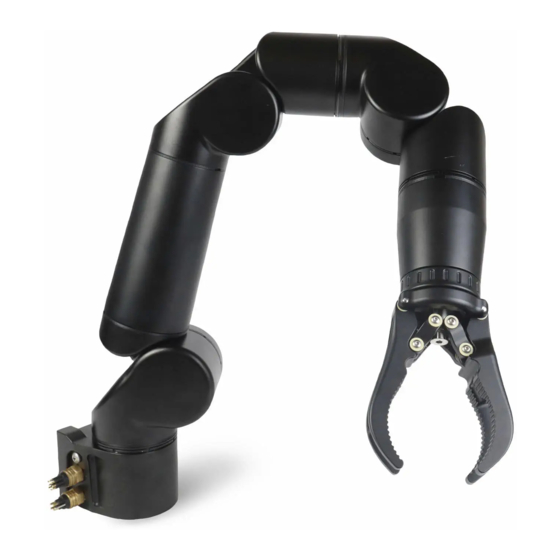
2 PRODUCT OVERVIEW The Reach Bravo is an advanced electric manipulator system that opens a new set of compact inspection and intervention opportunities for militaries, service providers, researchers, and other operators. Designed originally for the harsh subsea environment, and with an operating depth of 300m, the Reach Bravo is also suitable for austere out-of-water applications. -
Page 9: End-Effector Options
Bravo 3 – Three-Function Manipulator Bravo 2 – Two-Function Manipulator RB-3001 RB-2001 2.2 END-EFFECTOR OPTIONS Wide Quad Jaws Interlocking Quad Jaws (Stainless Steel option) RB-1025 RB-1041 (RB-1055) Parallel Jaws Cutter RB-1034 RB-1031 Image Not Available Page 8 of 37 Blueprint Lab Confidential Proprietary Information not to be reproduced or made available to third parties without prior consent from Blueprint Lab and not to be used in any unauthorised way. -
Page 10: Related Products And Accessories
2.3 RELATED PRODUCTS AND ACCESSORIES See respective manuals of related products for details. Master Arms Reach Control Pro RM-5201 and RM-7201 RC-2000 Page 9 of 37 Blueprint Lab Confidential Proprietary Information not to be reproduced or made available to third parties without prior consent from Blueprint Lab and not to be used in any unauthorised way. -
Page 11: Specifications
SPECIFICATIONS 3.1 MECHANICAL Bravo 7 Bravo 5 Bravo 3 Bravo 2 Functions Degrees-of-Freedom Full-Extension Reach 750mm 900mm 410mm 320mm (static) Dynamic Full- 10kg 12kg 15kg Extension Lift Base Joint Torque 110Nm 50Nm Max Dynamic Lift 15kg 20kg Max Axial Load 100kg 200kg Wrist Torque... - Page 12 Bravo 7 – Module breakdown. Bravo 7 – Range of Motion top view (left) and side view (right). Page 11 of 37 Blueprint Lab Confidential Proprietary Information not to be reproduced or made available to third parties without prior consent from Blueprint Lab and not to be used in any unauthorised way.
-
Page 13: Bravo 5
3.2.2 BRAVO 5 Bravo 5 – Dimensions and rotational capacity. Note: Base joint is software limited to 359° (not continuous). Figure 1 Bravo 5 module breakdown. Bravo 5 module breakdown. Page 12 of 37 Blueprint Lab Confidential Proprietary Information not to be reproduced or made available to third parties without prior consent from Blueprint Lab and not to be used in any unauthorised way. -
Page 14: Bravo 3
Bravo 5 – Range of motion top view (left) and side view (right). 3.2.3 BRAVO 3 Bravo 3 – Dimensions and rotational capacity Page 13 of 37 Blueprint Lab Confidential Proprietary Information not to be reproduced or made available to third parties without prior consent from Blueprint Lab and not to be used in any unauthorised way. - Page 15 Bravo 3 – Module breakdown Bravo 3 – Range of motion of the Bravo 3 (top view) Page 14 of 37 Blueprint Lab Confidential Proprietary Information not to be reproduced or made available to third parties without prior consent from Blueprint Lab and not to be used in any unauthorised way.
-
Page 16: Bravo 2
3.2.4 BRAVO 2 Bravo 2 – Dimensions and rotational capabilities. Bravo 2 – Module breakdown Note; Bravo 2 Range of Motion is limited to the continuous rotate joint only. Page 15 of 37 Blueprint Lab Confidential Proprietary Information not to be reproduced or made available to third parties without prior consent from Blueprint Lab and not to be used in any unauthorised way. -
Page 17: Environmental
3.3 ENVIRONMENTAL Operating Temperature Range -10°C to 35°C Storage Temperature Range -10°C to 70°C Depth Rating 300MSW Housing Material Hard Anodized AL6061 3.4 ELECTRICAL AND COMMUNICATION 3.4.1 POWER INTERFACE Bravo 7 Bravo 5 Bravo 3 Bravo 2 Input Voltage 20-48V 20-48V 24-48V 24-48V... -
Page 18: Interfacing And Integration
4 INTERFACING AND INTEGRATION Note: 3D CAD files for our manipulators are available upon request to assist with integration. 4.1 BRAVO 5 / BRAVO 7 4.1.1 MECHANICAL MANIPULATOR BASE INTEGRATION Page 17 of 37 Blueprint Lab Confidential Proprietary Information not to be reproduced or made available to third parties without prior consent from Blueprint Lab and not to be used in any unauthorised way. - Page 19 CONNECTOR CLEARANCE Page 18 of 37 Blueprint Lab Confidential Proprietary Information not to be reproduced or made available to third parties without prior consent from Blueprint Lab and not to be used in any unauthorised way. © Blueprint Lab Pty Ltd 2021...
-
Page 20: Electrical
4.1.2 ELECTRICAL POWER CONNECTOR - DWTEK MCBH4M Bulkhead Connector Receptacle Male Face View Pins Description Colour Black POWER White POWER Green Interface Cable (Supplied) MCIL4F - MC Inline, 4C Female to unterminated ends (100cm) COMMUNICATION CONNECTOR – DWTEK MCBH8ME Bulkhead Connector Receptacle Male Face View Pins Description... -
Page 21: Communication Protocol
4.2 BRAVO 2 / BRAVO 3 4.2.1 MECHANICAL MANIPULATOR BASE INTEGRATION Option 1 – Reach Bravo Mounting Kit Bravo 2 and 3 Mounting Kit Technical Drawings Page 20 of 37 Blueprint Lab Confidential Proprietary Information not to be reproduced or made available to third parties without prior consent from... - Page 22 Option 2 – Direct Backplate Integration Bravo 2/3 backplate technical drawing. Page 21 of 37 Blueprint Lab Confidential Proprietary Information not to be reproduced or made available to third parties without prior consent from Blueprint Lab and not to be used in any unauthorised way. © Blueprint Lab Pty Ltd 2021...
-
Page 23: Electrical
4.2.2 ELECTRICAL COMMUNICATION AND POWER CONNECTOR – DIL13F DBH13M Bulkhead Connector Receptacle Male Face View Inline cable colour code 1: Black 2: Screen (orange wire on bulkhead) 3: White *4-5: Brown, Brown/white *6-7: Blue, Blue/white *8-9: Orange, Orange/white *10-11: Green, Green/white 12: Red 13: Green * Twisted pairs... -
Page 24: Integration Electrical Diagram
4.3 INTEGRATION ELECTRICAL DIAGRAM The diagram below shows the basic electrical integration of a Bravo 7/5 and Master Arm controller, to a computer. Note that this is the same setup that is described in Bench Setup and Acceptance Test section of this manual. Page 23 of 37 Blueprint Lab Confidential Proprietary Information not to be reproduced or made available to third parties without prior consent from Blueprint Lab and not to be used in any unauthorised way. -
Page 25: Control Options
5 CONTROL OPTIONS Reach Bravo manipulators can be controlled by using the Reach Control Graphical User Interface, an external input such as a Gamepad or Blueprint Lab Master Arm, or by implementing the Reach Control Communication Protocol for custom control setups. -
Page 26: Master Arm
5.2.2 MASTER ARM The Blueprint Lab Master Arm system is a topside controller that maps the human operator control inputs to the movement of the manipulator’s joints in a corresponding manner. In this way, the Master Arm controller allows the manipulator to ‘mimic’ the movement of the operator. The following Master Arm products are available: Master Arm for Seven-Function Master Arm for Five-Function Reach... -
Page 27: Bench Setup And Acceptance Test
6 BENCH SETUP AND ACCEPTANCE TEST 6.1 BENCH SETUP This section outlines the basic setup and testing procedure users should complete to ensure their arm is fully operational. The following example is demonstrated with a Bravo 7. If you experience any issues in following these steps, please contact Blueprint Lab for technical support via info@blueprintlab.com. - Page 28 5) Ensure sheath is slid over pushrod. Rotate 6) Screw the collar to tighten. Fasten the pushrod if needed. screw with the 3/16 In. Allen key to secure. 7) Ensure the included power and 8) Plug the power and communications cables communications cables are securely into the arm.
-
Page 29: Communication Setup
1) On your Windows computer, press START > type “Settings” > Network and Internet > Ethernet > Change Adaptor Options. 2) Double click the ethernet connection to the Reach Bravo Arm. To check if you have the correct ethernet connection, unplug and re-plug the cable. The correct connection should disappear and reappear. -
Page 30: Reach Control
6.1.3 REACH CONTROL Reach Control will be provided to you digitally via email as well as on a USB within the Hard Carry Case. 1) Install Reach Control. 2) Open Reach Control > Settings (Cog Icon) > Ports > Add. Click the new Port. - Page 31 3) Click Settings (Cog Icon) > Device Select the existing device (or click add if none exist). Select the name of the port just created. Select the type of manipulator. 4) If the Bravo is setup correctly, the 3D model in the background will update to reflect the physical position of the manipulator.
-
Page 32: Acceptance Test
6.2 ACCEPTANCE TEST 6.2.1 RANGE OF MOTION TEST 1) On the control panel in the bottom right of Reach Control, click the velocity button. Directional arrows will appear on the 3D model. 2) Click Settings (Cog Icon) > Display > Feedback. The monitoring panel will open at the bottom of the screen. - Page 33 4) All Bravo products are shipped with a virtual obstacle to prevent collision with the ‘floor’ under the base of the manipulator. 5) Move each joint for a few seconds in each direction. Ensure movement is as expected and corresponds with control input. Page 32 of 37 Blueprint Lab Confidential Proprietary Information not to be reproduced or made available to third parties without prior consent from Blueprint Lab and not to be used in any unauthorised way.
-
Page 34: Master Arm Test (If Applicable)
6.2.2 MASTER ARM TEST (IF APPLICABLE) 1) Set up the Master Arm with the stand 2) Connect Master Arm to the computer via provided. USB. 3) Once powered, the Master Arm buttons will flash blue. 4) Open Reach Control, Settings (Cog Icon) > Ports > Add. Assign the new port a Name and select the comm port the Master Arm is communicating on. - Page 35 5) Settings (Cog Icon) > Control. If there is no Master Arm option underneath Spacemouse, click Add. Assign the new Control port a name. Set ‘Port’ to the name of your Master Arm port. Set ‘Device’ to the name of the Slave arm you wish to control. 6) The Master Arm is now ready to control the slave manipulator.
- Page 36 7) Move each Master Arm joint through its full range of motion. Note: J1 and J2 are controllable from the Master Arm Joystick. Check that: The corresponding joint on the slave arm responds. b. The joint moves in the correct direction. The motion of slave to master is a 1-to-1 ratio.
-
Page 37: Recommended Servicing Schedule
7 Recommended Servicing Schedule The Reach Bravo system is recommended for an OEM Servicing every one (1) year or 200 operational hours, whichever occurs first. Blueprint Lab offer a capped price service with each new Reach Bravo system. The coverage period of the capped price service program is for a period of two (2) years, or 200 operational hours, whichever occurs first. -
Page 38: Revision History
9 REVISION HISTORY Name Date Change V1.0 Anders 26 May 20 First Version V2.0 James 25 Aug 20 Inclusion of Bravo 2 & 3. Electrical Diagrams. Setup and Integration information. Acceptance Testing. V3.0 James Jan 2021 Bravo 2/3 Module breakdowns and Mounting kit diagrams. SS jaws added.
Need help?
Do you have a question about the REACH BRAVO and is the answer not in the manual?
Questions and answers