Advertisement
Quick Links
Quick Start Guide
(8200-1937-01_C0)
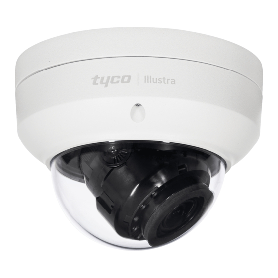
Illustra Flex Gen 3 Indoor Dome Camera
In the box
y 1 x Indoor dome camera
y 1 x Mounting template sticker
y 1 x Mounting plate
y 2 x 50x4mm tapping screws
y 2 x 40x6mm plastic screw anchors
y 2 x 10x4mm mounting plate screws
y 1 x Printed Quick Start Guide
Installation tools
y 1 x Drill
y 1 x Screw Driver
Camera Parts: Figure 1
1
2
3
4
5
6
Figure 1
Quick reference
y Default IP: 192.168.1.168 (DHCP enabled)
y Default Username / Password: admin / admin
y Power: AC24V / PoE 802.3af
Table 1: Camera part descriptions
Camera Part
Description
1
Mounting Plate
2
Camera base
Camera body
3
4
Camera Lens
5
Camera lens cover
6
Dome Cover
Mounting and powering up the camera
1. Place the mounting template sticker on the surface that you want to
attach the camera.
2. On the surface drill two Ø 6mm holes and cut out a cable hole as per
the markings identified on the mounting template sticker.
3. Securely place the two screw anchors into the two Ø 6mm holes.
Mounting and powering up the camera (continued)
4. Hold the camera dome with one hand and rotate the camera base to
unlock it and remove it from the dome.
Note: The camera dome includes a 'lock' and 'unlock' symbol to assist
with step 4.
5. Gently pull up and remove the camera lens cover (5) (Figure 1) to
easily access the cable connections and buttons.
6. Connect the PoE cable to the PoE slot on the camera or the AC24V
cable to the AC24 connection on the camera.
7. Before you secure the mounting plate (1) (Figure 1) to the camera base
(2) (Figure 2) you must place the cable through the cable hole on the
camera mounting plate.
8. Place the mounting plate onto the camera base so that the three
semicircular swellings on the mounting plate fit correctly into the three
screw holes on the camera base.
9. Place the cable through the cable hole on the mounting surface.
10. Hold the mounting plate with camera base up to the mounting template
and align two screw holes on the camera base with the two screw holes
on the mounting surface.
11. Insert the two screws into the two holes on the camera base and
securely attach the mounting plate and camera base to the surface.
12. Insert the camera lens cover (5) (Figure 1) on to the camera lens.
Mounting and powering up the camera (continued)
13. Hold the camera dome (6) (Figure1) up to the camera base and rotate
the camera dome to securely lock it to the camera base.
Note: The camera dome includes a 'lock' and 'unlock' symbol to assist
with step 13.
14. Connect the AC 24V cable to an AC 24V terminal or connect the RJ-45
jack to a PoE compatible network device that supplies power through
the Ethernet cable.
Camera buttons and connections: Figure 2
1
2
3
4
5
6
Figure 2
Table 2: Camera buttons and connections descriptions
Camera button /
Description
connection
1
AC cable connection
USB cable connection
2
Factory reset
3
y Hold for 5 seconds for soft reset
y Hold for 20 seconds for hard reset
Focus button
4
y Hold for 3 seconds to run one touch focus
5
Audio / Alarm cable connection
6
Micro SD card insert
PoE cable slot
7
7
Advertisement

Subscribe to Our Youtube Channel
Related Manuals for Tyco Illustra Flex Gen 3


Summary of Contents for Tyco Illustra Flex Gen 3
- Page 1 (8200-1937-01_C0) 14. Connect the AC 24V cable to an AC 24V terminal or connect the RJ-45 jack to a PoE compatible network device that supplies power through Illustra Flex Gen 3 Indoor Dome Camera Camera Part Description the Ethernet cable.
- Page 2 Note: The camera dome includes a ‘lock’ and ‘unlock’ symbol to assist JOHNSON CONTROLS, TYCO and ILLUSTRA are trademarks and/or with the above step. registered trademarks. Unauthorized use is strictly prohibited.
Need help?
Do you have a question about the Illustra Flex Gen 3 and is the answer not in the manual?
Questions and answers