
Related Manuals for Icom IC-M59euro


Summary of Contents for Icom IC-M59euro
-
Page 1: Instruction Manual
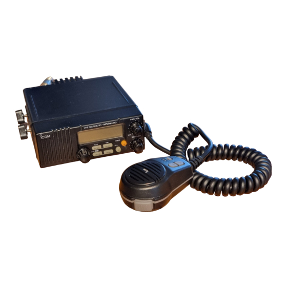
INSTRUCTION MANUAL VHF MARINE TRANSCEIVER iC- m59 euro PWR/VOL VHF MARINE SQUELCH SCAN DUAL HI/LO DIAL... -
Page 2: In Case Of Emergency
IN CASE OF EMERGENCY If your vessel requires assistance, contact other vessels and Or, transmit your distress call using digital selective calling on the Coast Guard by sending a distress call on channel 16. channel 70 (the optional UX-120 with RC-18 DSC UNIT must be installed). -
Page 3: Table Of Contents
TABLE OF CONTENTS IN CASE OF EMERGENCY ..........i 4 DIGITAL SELECTIVE CALLING ......12 – 17 TABLE OF CONTENTS ............ii General ..............12 IMPORTANT ..............iii Distress call transmission ......... 13 CAUTIONS................iii All ships call transmission ......... 14 Receiving DSC calls .......... -
Page 4: Important
IMPORTANT READ ALL INSTRUCTIONS YOU MUST HAVE carefully and com- a DSC vessel ID in order to operate pletely before using the transceiver. the optional DSC functions of the transceiver. See your Dealer for details. SAVE THIS INSTRUCTION MANUAL— This in- struction manual contains important operating instructions for The IC-M59 complies with the essential requirements of... -
Page 5: Operating Rules
OPERATING RULES OPERATOR’S LICENSE D Priorities A restricted Radiotelephone Operator Permit is the license • Read all rules and regulations pertaining to priorities and most often held by small vessel radio operators when a radio keep an up-to-date copy handy. Safety and distress calls is not required for safety purposes. -
Page 6: Panel Description
PANEL DESCRIPTION Front panel Function display (p. 4) PWR/VOL VHF MARINE Speaker SQUELCH SCAN DUAL HI/LO DIAL CHANNEL SELECTOR HIGH/LOW POWER SWITCH [HI/LO• Selects an operating channel in the selected channel • Toggles between high and low output powers. (p. 9) group. -
Page 7: Microphone
PANEL DESCRIPTION DUAL/TRI-WATCH SWITCH [DUAL• Microphone • Activates dualwatch for checking channel 16. (p. 8) • Push and hold for 1 sec. to activate tri-watch for checking channel 16 and the call channel. (p. 8) CALL CHANNEL SWITCH [C• • Selects the call channel—the call channel is programma- ble. -
Page 8: Function Display
PANEL DESCRIPTION Function display BUSY TAG DUAL LOW CALL SCAN SCRM DUP ACK RCV TRANSMIT INDICATOR SCAN INDICATOR Appears while transmitting. (p. 9) Appears and flashes during scan operation. (p. 10) BUSY INDICATOR DUALWATCH INDICATOR Appears when receiving a signal or when [SQUELCH] is Appears and flashes during dualwatch operation. -
Page 9: Distress Switch Box
PANEL DESCRIPTION Distress switch box DUPLEX INDICATOR (UX-120 required) Appears when the selected channel is a duplex channel (p. 7). ACKNOWLEDGEMENT/RECEIVE INDICATORS VHF DSC Appear during optional DSC operation. (pgs. 13–17) • “RCV” appears when a DSC call is received. •... -
Page 10: Basic Operation
BASIC OPERATION Power ON Channel selection Rotate [PWR/VOL] clockwise to turn power ON. D Channel 16 Channel 16 is the distress channel. It is used for establishing All display indications BUSY TAG DUAL initial contact with another station and for emergency com- LOW CALL SCAN appear briefly*. - Page 11 BASIC OPERATION D International channels D U.S.A. channels (U.K. and Italy versions only) There are 55 international channels for the IC-M59 For the U.K. and Italy versions, there are 61 U.S.A. channels EURO in addition to 55 international channels. These channel Push [DIAL] to select an international channel.
-
Page 12: Receiving
BASIC OPERATION Receiving • Dualwatch operation Push [DUAL• ] momentarily for dualwatch. Rotate [PWR/VOL] to turn power ON. Rotate [SQUELCH] fully counterclockwise. DUAL Adjust [PWR/VOL] to a suitable listening level. BUSY DUAL Rotate [SQUELCH] clockwise until the audio noise disap- pears. -
Page 13: Transmitting
BASIC OPERATION Transmitting CALL PROCEDURES You must identify yourself when you transmit and you must Before transmitting, read the call procedures at right. respect time limits. Select an operating channel. See pgs. 6, 7 for details. 1) Give your call sign each time you call another vessel or a Push [HI/LO] to select transmit output power. -
Page 14: Scan Function
BASIC OPERATION Scan function D Setting tag channels You can specify channels as tag channels for efficient scanning. The transceiver has a high speed scan function (8 chan- Select the desired channel, then push and hold nels/sec.) for standing by on utility signals. •TAG] for 1 sec. -
Page 15: Call Channel Programming
BASIC OPERATION Call channel programming Display backlighting The call channel key, [C], is used to select the call channel The function display and switches can be backlit for better vis- which you can program your most often-used channels. ibility under low light conditions. Push [C] to select the call While pushing [ •DIM], rotate the channel selector to ad-... -
Page 16: Digital Selective Calling
DIGITAL SELECTIVE CALLING UX-120 required General cially useful for distress calls and other urgent matters) can When an optional UX-120 with RC-18 DSC UNIT DISTRESS be pre-programmed into a radio and transmitted accurately. is installed, digital selective calling (DSC class-F) SWITCH BOX is available with via the IC-M59 EURO... -
Page 17: Distress Call Transmission
DIGITAL SELECTIVE CALLING Distress call transmission CAUTION: When a distress acknowledge- Distress calls may be transmitted under BUSY ment is received, emergency conditions of emergency only i.e. your vessel is in danger ACK RCV alarm sounds and channel 16 of sinking and/or a person’s life is in danger. is automatically selected. -
Page 18: All Ships Call Transmission
DIGITAL SELECTIVE CALLING All ships call transmission Large ships use channel 70 as their “listening channel.” When Push and hold [PTT] to send an announcement via the mi- you want to announce a message to these ships, use the “all crophone to all ships. -
Page 19: Receiving Dsc Calls
DIGITAL SELECTIVE CALLING Receiving DSC calls D Receiving a distress call While monitoring channel 70 and a distress call is received: Several types of DSC transmissions can be received. The re- Emergency alarm sounds. quired action depends on the particular DSC type as outlined BUSY “RCV”... - Page 20 DIGITAL SELECTIVE CALLING D Receiving an all ships call D Receiving an individual call While monitoring channel 70 and an all ships call is received: When receiving an individual call, an acknowledgement is transmitted automatically. The contents of the acknowledge- Beeps or emergency alarm ment must be specified in advance.
- Page 21 DIGITAL SELECTIVE CALLING While selecting “Able to comply” and an individual call D Receiving a geographical area call is received: While monitoring channel 70 and a geographical area call (for the area you are in) is received: Emergency alarm or beeps BUSY sound depending on the re- Emergency alarm or beeps...
-
Page 22: Set Mode
SET MODE Entering SET mode SET mode items SET mode is used to customize operation of the transceiver to suit your operating needs. Beep tones D To enter SET mode: While pushing [16], turn power ON. • Keep pushing [16] until the initial SET mode display appears. Normal/priority •... - Page 23 SET MODE D BEEP TONES D AUTO ACKNOWLEDGE CONTENTS This item sets the transceiver’s confirmation beep tones (when (appears when the UX-120 is installed) pushing a switch/rotating ‘channel selector’) ON or OFF. This item sets “unable to comply” or “able to comply” as the automatic acknowledgement when receiving an individual call.
-
Page 24: Connection And Maintenance
CONNECTION AND MAINTENANCE Unpacking Additional requirements q Mounting bracket ............. 1 D For general operation w DC power cable (OPC-355) ..........1 • Marine VHF antenna e Microphone hanger (OPC-562) ........1 • Coaxial cable r Mounting bracket knobs ........... 4 t Mounting screws (5 ×... -
Page 25: Connections
CONNECTIONS AND MAINTENANCE Connections Insert the cable lug into The rear panel for the Italy version this space after removing differs slightly from that shown here, the screw. however connections are basically Attach the supplied rub- the same. ber cap after tightening the screw. -
Page 26: Mounting The Transceiver
CONNECTIONS AND MAINTENANCE Mounting the transceiver DASHBOARD MOUNTING (with optional MB-28) The universal mounting bracket supplied with your transceiver allows overhead or dashboard mounting. Please read the fol- lowing instructions carefully. • Mount the transceiver securely with the 4 supplied screws (M5 ×... -
Page 27: Antenna
CONNECTIONS AND MAINTENANCE Antenna Cleaning A key element in the performance of any communication sys- If the transceiver becomes dusty or dirty, wipe it clean with a tem is an antenna. Ask your Dealer about antennas and the dry, soft cloth. best places to mount them. - Page 28 CONNECTIONS AND MAINTENANCE Opening the transceiver case UX-120 installation (Fig. 3) (Fig. 1) q Secure the UX-120 in place with 2 supplied screws. Be careful not to shift the connector. Apply 4 to 6 kg torque when replacing screws. UT-79 installation (Fig. 2) Attach to its original position.
-
Page 29: Vhf Marine Channel List
VHF MARINE CHANNEL LIST • International channels Frequency (MHz) Frequency (MHz) Frequency (MHz) Frequency (MHz) Frequency (MHz) Frequency (MHz) Transmit Receive Transmit Receive Transmit Receive Transmit Receive Transmit Receive Transmit Receive 156.050 160.650 156.550 156.550 157.050 161.650 156.125 160.725 156.625 156.625 157.225 161.825 156.100 160.700 156.600 156.600... -
Page 30: Specifications
SPECIFICATIONS General Transmitter • Frequency coverage : Transmit 156–157.5 MHz • Output power : High 25 W Low 1 W Receive 156–163 MHz • Modulation system : Variable reactance phase • Usable channels : All International channels modulation All U.S.A. channels additionally for •... -
Page 31: Options
OPTIONS MB-28 FLUSH MOUNT SP-10 EXTERNAL SP-5 EXTERNAL PS-66 For mounting the IC-M59 EURO SPEAKER SPEAKER DC-DC CONVERTER to a panel. Available in black A compact, external speaker. A large, external speaker for Input voltage: 19 to 32 V DC or white. - Page 32 Count on us! A-5498D-1EU Printed in Japan 6-9-16 Kamihigashi, Hirano-ku, Osaka 547-0002 Japan © 1998 Icom Inc.
Need help?
Do you have a question about the IC-M59euro and is the answer not in the manual?
Questions and answers