Table of Contents
Advertisement
Quick Links
Technical Services: Tel: (800) 381-9312 / Fax: (800) 791-5500
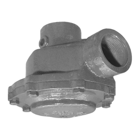
Preaction System with Model DV-3 Deluge Valve
Double Interlock, Electric/Pneumatic Release
2-1/2 Inch (DN65)
FIGURE 1
2-1/2 INCH (DN65) ELECTRIC/PNEUMATIC DOUBLE INTERLOCK PREACTION SYSTEM
— SCHEMATIC OF TYPICAL ARRANGEMENT —
Page 1 of 10
JANUARY, 2005
TFP1462
Advertisement
Table of Contents

Related Manuals for Tyco DV-3


Summary of Contents for Tyco DV-3
- Page 1 Technical Services: Tel: (800) 381-9312 / Fax: (800) 791-5500 Preaction System with Model DV-3 Deluge Valve Double Interlock, Electric/Pneumatic Release 2-1/2 Inch (DN65) FIGURE 1 2-1/2 INCH (DN65) ELECTRIC/PNEUMATIC DOUBLE INTERLOCK PREACTION SYSTEM — SCHEMATIC OF TYPICAL ARRANGEMENT — Page 1 of 10...
-
Page 2: General Description
In order for the Double Interlock Pre- The 2-1/2 inch (DN65) Model DV-3 action System to automatically actu- Electric/Pneumatic Double Interlock WARNING ate, two independent events must oc- Preaction System (Ref. -
Page 3: Technical Data
TFP1462 Page 3 of 10 GRAPHS A-1 and A-2 NOMINAL PRESSURE LOSS VERSUS FLOW FOR THE MODEL DV-3 DOUBLE INTERLOCK PREACTION SYSTEM (DELUGE VALVE, ELBOW, AND CHECK VALVE COMBINATION) Technical Data Approvals UL and C-UL Listed as Double Inter- lock Type Water Control Valves. FM... - Page 4 TFP1462 Page 4 of 10 FIGURE 3 — PART 1 of 2 2-1/2 Inch (DN65) DOUBLE INTERLOCK PREACTION TRIM (See Page 5 for Bill of Materials)
-
Page 5: Operation
Pilot Actuator and the Solenoid Valve Figure 1. The System Shut-Off Valve Model MC-1 Manual must occur to actuate the Model DV-3 should be a listed or approved (as ap- Control Station .. -
Page 6: Installation
Page 6 of 10 PORV Operation Area “A” of the PORV is connected directly to the top of the DV-3 Dia- phragm Chamber. In the set position, water pressure is supplied through the Screen (16) and the orifice in the Diaphragm (14) to both sides of the Diaphragm, Areas “A”... -
Page 7: System Setting Procedure
Drainage water must be directed such Automatic Drain Valve (Fig. 3), to verify that it will not cause damage or result that it is open and that the DV-3 Valve in dangerous conditions. has been completely drained. The Double Interlock Preaction Sys- tem must be manually reset, and it Step 10. -
Page 8: Care And Maintenance
This procedure is used to verify that leakage problem. If there are no leaks, stalling contractor or product manufac- the DV-3 Deluge Valve will remain set fully open the Main Control Valve (Fig. turer should be contacted relative to if the electric detection system oper- any questions. -
Page 9: Limited Warranty
This procedure is used to verify that original Buyer for ten (10) years cordance with Figure 4 and then rein- the DV-3 Deluge Valve will remain set against defects in material and work- stall the PORV into the Double Inter-... -
Page 10: Ordering Procedure
• Preaction Trim ELECTRIC/PNEUMATIC DOUBLE INTERLOCK PREACTION TRIM • Automatic Pressure Maintenance Specify: (specify finish — galvanized is standard) Preaction Trim for Model DV-3 Deluge Device Valves, P/N (specify). Galvanized ............
Need help?
Do you have a question about the DV-3 and is the answer not in the manual?
Questions and answers