Advertisement
Quick Links
Advertisement

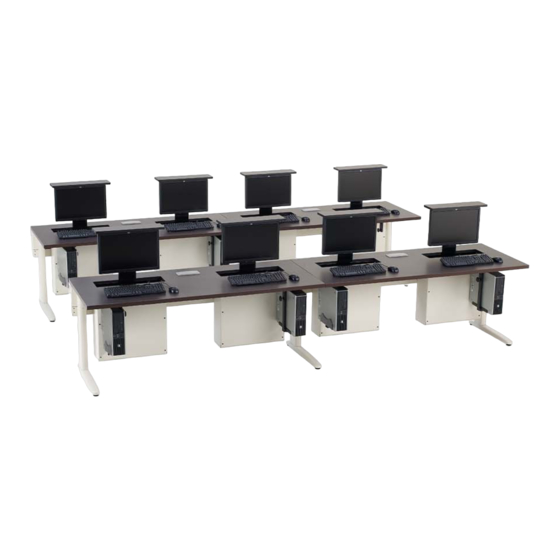
Summary of Contents for KI Smart Lift
- Page 1 Assembly Instructions Smart Lift Table System ® February 2015...
- Page 3 • Screw Gun, Battery, Charger assembly upside down on a soft, • T25 Torx Drive Bit protective surface. Unpack the • #2 Phillips Drive Bit Smart Lift unit and locate the • ⁄ ” Hex Allen Wrench installation kit (Detail A) within Smart Lift™...
- Page 4 If the desk has another Smart Lift unit, attach its remote lock wire garage housing plug into the remaining female remote lock wire garage housing plug.
- Page 5 Smart Lift Table System ® Assembly Instructions Assemble units as described herein only. To do otherwise may result in instability. All screws, nuts and bolts must be tightened securely and must be checked periodically after assembly. Failure to assemble properly, or to secure parts may result in assembly failure and personal injury.
- Page 6 “lock button” on the remote key FOB and then press the “un-lock button” (Figure 8). Press buttons again to verify that the key FOB correctly controls the solenoid locking mechanism to lock or un-lock the Smart Lift unit.
- Page 7 Smart Lift Table System ® Assembly Instructions Assemble units as described herein only. To do otherwise may result in instability. All screws, nuts and bolts must be tightened securely and must be checked periodically after assembly. Failure to assemble properly, or to secure parts may result in assembly failure and personal injury.
- Page 8 Smart Lift Table System ® Assembly Instructions Assemble units as described herein only. To do otherwise may result in instability. All screws, nuts and bolts must be tightened securely and must be checked periodically after assembly. Failure to assemble properly, or to secure parts may result in assembly failure and personal injury.
- Page 9 Smart Lift Table System ® Assembly Instructions Assemble units as described herein only. To do otherwise may result in instability. All screws, nuts and bolts must be tightened securely and must be checked periodically after assembly. Failure to assemble properly, or to secure parts may result in assembly failure and personal injury.
- Page 10 Smart Lift Table System ® Assembly Instructions Assemble units as described herein only. To do otherwise may result in instability. All screws, nuts and bolts must be tightened securely and must be checked periodically after assembly. Failure to assemble properly, or to secure parts may result in assembly failure and personal injury.
- Page 11 Refer 4mm screw diameter clearance holes in pivot to Smart Lift monitor storage bracket, matching the VESA hole installation for additional pattern in flat screen monitor, and instructions (Figure 16). torx drive screw...
- Page 12 1330 Bellevue Street P .O. Box 8100 Green Bay, Wisconsin 54308-8100 1-800-424-2432 www.ki.com Ki is a registered trademark of Krueger International, Inc. © 2015 KI All Rights Reserved Code KI-62216R2/KI/PDF/0215...


Need help?
Do you have a question about the Smart Lift and is the answer not in the manual?
Questions and answers