Table of Contents
Advertisement
Advertisement
Table of Contents

Related Manuals for Xtool IP616


Summary of Contents for Xtool IP616
- Page 1 User Manual IP616 Smart Diagnostic System Shenzhen Xtooltech Intelligent Co., LTD...
-
Page 2: Copyright
CO., LTD. In countries where the trademarks, service marks, domain names, logos and the name of the company are not registered, XTOOL claims that it still reserves the ownership of the unregistered trademarks, service marks, domain names, logos and the company name. All other marks for the other products and the company’s name mentioned in the manual still... -
Page 3: Declaration
ECLARATION This manual is designed for the usage of the IP616 Smart Diagnostic System and provides operating instructions and product descriptions for users of the IP616 Smart Diagnostic system. No part of this manual can be reproduced, stored in a retrieval system, or... -
Page 4: Aftersales-Services
Do not touch the cooling system components or exhaust manifolds when the engine is running due to the high temperatures reached. Make sure the car is securely parked, Neutral is selected or the selector is at P or N position to prevent the vehicle from moving when the engine starts. -
Page 5: Table Of Contents
ONTENT TRADEMARKS ................I COPYRIGHT ..................I DECLARATION ................II OPERATION INSTRUCTIONS ............II CAUTIONS! ................... III AFTERSALES-SERVICES ............III CONTENT ..................IV GENERAL INTRODUCTION ........... 1 Tablet ....................1 Front View of Tablet ..................1 Back View of Tablet ..................2 Host Ports ......................3 Technical Specifications ............... - Page 6 UPDATE ................. 14 DIAGNOSTIC ................. 15 Vehicle Connection ................15 Diagnostic ................... 17 Vehicle Selection..................17 Diagnostic functions ...................20 SPECIAL FUNCTIONS ............28 5.1 OIL RESET ................... 29 5.2 EPB ....................31 5.3 SAS ....................33 5.4 DPF ....................36 5.5 BMS RESET ................. 40 5.6 THROTTLE ...................
- Page 7 Report ....................55 Replay ....................58 File Manager ..................59 REMOTE ASSISTANCE ............59 FAQ ..................61 Q1: Failed to generate Diagnostic report ..........61 Q2: How to print Diagnostic report ............62 Q3: Failed to extract files ..............63 Q4: Mailbox supported ................63 Q5: How to make an appointment for remote support ......
-
Page 8: General Introduction
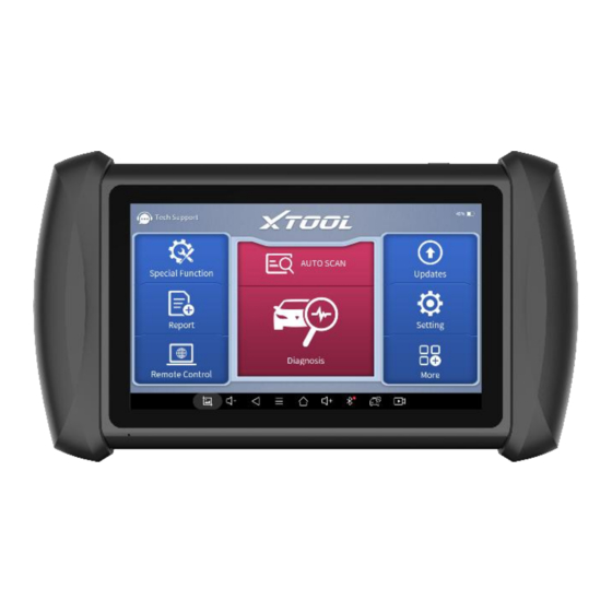
ENERAL NTRODUCTION The XTOOL IP616 smart diagnostic system is an advanced flatbed scanning tool based on the Android operating system. It supports multi- language switching and is suitable for different countries and regions. The advantage of this obd2 scanner is not only its comprehensive functions,... -
Page 9: Back View Of Tablet
Operation Display: Display basic information such as S/N and model etc. The main unit of the IP616 is the tablet, which has a built-in VCI module, which can be directly connected to the tablet and the car with the test line. -
Page 10: Host Ports
HOST PORTS ① ④ ② ③ Fig 1-3 Tablet Host Ports USB Port: Data synchronization with PC. DB15 Port: This port is used to connect to the main test cable. DC charging port: This port is used for charging. Power Button: Long press to power on or off. In the power-on state, short press the button to make the device enter sleep mode. -
Page 11: Package Kit
Sensors Gravity sensor, light sensor Microphone, dual speakers, 4-band Auto Input/Output 3.5mm stereo/standard headset jack Power and Battery 5000mAh, 3.65V lithium-polymer battery Power Voltage Power Consumption Operating Temperature -20 to 60℃(-4 to 140℉) Storage Temperature -40 to 70℃(-40 to 158℉) Humidity <90% Dimension (L*W*H) -
Page 12: Getting Started
ETTING TARTED ACTIVATION After first-time users press and hold the power button to turn on the system, the system will automatically enter the guide process and request to select the language for the operating system. Fig 2-1 Sample of Select Languages before Activation After setting the system language, you will enter the activation page, as shown in the figure below. - Page 13 Fig 2-2 Sample of Activation, screen 1 Click Start Activate to enter the activation page, as shown below: Fig 2-3 Sample of Activation, screen 2 A pop-up window showing Activation Success indicates that you have completed the first boot setup, click OK to enter the diagnostic system and start using the device.
-
Page 14: Main Interface
Fig 2-4 Sample of Activation Succussed MAIN INTERFACE OPERATION SYSTEM As shown in the figure below, this interface is the main page of the operating system of the device. You can also return to this interface at any time by clicking 【⚪】on the bottom navigation bar. Fig 2-5 Sample of Android system home page... - Page 15 Settings for Android System Browser: Click on the browser icon to enter the browser to view the official website of XTOOL or search for other information. Gallery: Click the Gallery icon to enter the album to quickly view the pictures or screenshots stored on the device. You can select the...
-
Page 16: Diagnostic System Entrance
You can manage the APP, music, files, pictures, etc. in the device in this function, and you can also use Local/Home/Cleaner to clean up files. DIAGNOSTIC SYSTEM ENTRANCE Once activated, you will automatically enter the diagnostic system with the following main screen. Tap on the Diagnostic application button on the menu, the main interface will be shown as below: Fig 2-7 Sample of the Main Menu of the diagnostic program The main interface is mainly composed of Function Buttons and... -
Page 17: Navigation Buttons
Table 2-2 Sample of function buttons Item Description Quickly access the vehicle system to identify the VIN Enter to select a vehicle Includes special functions for car Diagnostic You can view the vehicle diagnostic report In case of failure, you can control the diagnostic equipment remotely Users can upgrade the available software with one click Users can set the language, unit, Bluetooth, and repair... -
Page 18: Notification Bar
Shows recently used applications Back to the main interface of the Android system Increase volume Showing the Bluetooth states Click this button to return to the diagnostic vehicle interface Press for screen recording NOTIFICATION BAR Slide down to open the notification bar. Users can adjust the brightness of the screen when they need it, and you can also connect Wi-Fi and so on. -
Page 19: Factory Reset
FACTORY RESET When you choose to restore factory settings in the Android OS system, the device will automatically restart and enter the factory mode to pull the software. You can select the language in the following interface. Fig 2-9 Select the Languages of the Android system After selecting the system language, click Next to enter the Wi-Fi connection page, as shown below: Fig 2-10 Connect to Wi-Fi... - Page 20 Select a network to connect to on the Wi-Fi connection page. After a successful network connection, the automatic system will jump to Factory mode to download the software: Fig 2-11 Install all applications Once the software has been downloaded, the tablet will automatically reboot and request the system language selection again.
-
Page 21: Update
Since restoring the factory settings will erase the user information on your device, you need to enter the email again to activate your device PDATE After activating the device, please update the software in "Update" first. The device will pull all currently supported software packages, and you can download them as needed. -
Page 22: Diagnostic
(ABS), airbag system (SRS), and perform kinds of actuation tests. VEHICLE CONNECTION The Diagnostic operation needs to connect the IP616 smart Diagnostic system to a vehicle first so that the tablet can establish correct vehicle communication. Please perform the following steps: Turn on the tablet;... - Page 23 H6 Elite diagnostic function, please upgrade the vehicle diagnostic software to the latest version or consult the technical service department; 5. It is forbidden to use wiring harnesses other than Xtool for connection testing to avoid unnecessary losses;...
-
Page 24: Diagnostic
DIAGNOSTIC After the tablet device is properly connected to the vehicle, you could start the vehicle diagnosis. VEHICLE SELECTION The IP616 supports the following 3 ways to access the smart Diagnostic system. AUTO SCAN MANUAL INPUT SELECT VEHICLE BY AREA ... - Page 25 AUTO SCAN: It supports automatic reading of vehicle VIN code. You also can tap on the button “AUTO SCAN” on the diagnosis system entrance to use this function. Please make sure that the car and the device are well connected before using this function. If your model is not recognized, please try the following steps: UPDATE all software, and check whether the APP is updated in [Settings]...
- Page 26 In addition to the above 3 methods, you can also choose a car brand according to the region. You can select the vehicle model that needs to be diagnosed according to the area, as shown below: Figure 4-5 Sample of Vehicle Selection by Ares OBD- Ⅱ...
-
Page 27: Diagnostic Functions
Enter "System Selection", you can also diagnose the vehicle according to the system according to your needs after selecting the model. DIAGNOSTIC FUNCTIONS Diagnostic functions supported by IP616 Smart Diagnostic System are as below:: Read ECU Information Read/Clear Trouble Code ... - Page 28 Figure 4-8 Sample of ECU Information READ TROUBLE CODE Figure 4-9 Sample of reading DTC ※ NOTE: In the process of diagnosis, if the device shows “System is OK” or “No Trouble Code”, it means there is no related trouble code stored in ECU or some troubles are not under the control of ECU, most of these troubles are mechanical system troubles or executive circuit troubles, it is also possible that signal of the sensor may bias within limits, which can be judged in Live...
- Page 29 CLEAR TROUBLE CODE It allows clearing current and historical trouble codes memory in ECU, under the premise that all the troubles are eliminated. Figure 4-10 Sample of Clear DTC The trouble codes can’t be erased without eliminating all the troubles, which will cause the diagnostic tool to always read the trouble code because the code will always be saved in ECU.
- Page 30 Figure 4-11 Sample of PIDs List Click the magnifying glass on the top right, you can search for related PIDs based on keywords Figure 4-12 Sample of the PIDs List related by Key Words Custom ...
- Page 31 Figure 4-13 Sample of Custom the PIDs Support to show the selected PIDs. Click Display All, back to the page which displays all PIDs Combine Support to select multiple PIDs and click Combine to make different graphs into one chart. Figure 4-14 Sample of the PIDs Combination...
- Page 32 Data recording Supports recording the current data value in the form of text, you can view the recorded files in Reports->Data Replay. Figure 4-15 Data Recording, Screen 1 Figure 4-15 Data Recording, Screen 2 Pause ...
- Page 33 Click this button to pause the timeline FREEZE FRAME When the signal of the sensor is abnormal, the ECU will save the data at that moment of failure to form a freeze-frame. It is usually used to analyze the reasons that may lead to car failures. The living data items supported by vehicles of different brands are not the same, so the freeze frames displayed when diagnosing vehicles of different brands may also be different.
- Page 34 Figure 4-17 Sample of the Freeze frame for Renault Duster ii ph (Screen 2) Context when fault appeared: record the live data when fault appeared to help the user to know the vehicle status. *Some vehicles don't support this function; users will get a prompt when they click the menu. Current context: Displays the current live data stream associated with the DTC Figure 4-18 Sample of the Freeze frame for Renault Duster ii ph (Screen 3)
-
Page 35: Special Functions
Figure 4-19 Sample of the Freeze frame for Renault Duster ii ph (Screen 4) PECIAL UNCTIONS The IP616 Smart Diagnostic System supports a lot of commonly used special reset functions, allowing you to quickly access your vehicle system for various scheduled services, maintenance, and reset performance, eliminating the need to reset after resolving common problems. -
Page 36: Oil Reset
Figure 5-1 Sample of Special Functions 5.1 OIL RESET Reset the Engine Oil Life System, which calculates the optimum oil life change interval based on the vehicle’s driving conditions and climate. The oil life reminder must be reset each time the oil is changed so that the system can calculate when the next oil change is required. - Page 37 Figure 5-2 Sample of oil reset function (screen 1) Enter the Maintenance mileage reset menu. Input reasonable value of mileage and press OK. Figure 5-3 Sample of oil reset function (screen 2) Message of ‘Reset success’ displayed when Oil Reset function has successfully performed.
-
Page 38: Epb
5.2 EPB Electronic Parking Brake (EPB) System reset is a popular special function. You can use this function to reset the electronic parking brake system and brake pads, which also supports the brake pad replacement (retraction, release of the brake pump), G-sensor, and body angle calibration. This function has multiple uses and can safely and effectively maintain the electronic brake system. - Page 39 Figure 5-4 Sample of EPB function (screen 1) Enter the Enter maintenance mode menu and release the handbrake brake. And press OK after completing the instructions shown. Figure 5-5 Sample of EPB function (screen 2) Wait until the message ‘Successful operation’ pops up. And press OK to exit the menu.
-
Page 40: Sas
Enter the Exit maintenance mode menu and wait until the message of ‘‘Successful operation’ popes up. 5.3 SAS Steering Angle Sensors (SAS) System Calibration permanently stores the current steering wheel position as the straight-ahead position in the SAS EEPROM. Therefore, the front wheels and the steering wheel must be set exactly to the straight-ahead position before calibration. - Page 41 Figure 5-6 Sample of SAS function (screen 1) Wait until the following instruction is displayed and press Yes after completing the instructions shown. Figure 5-7 Sample of SAS function (screen 2) Follow the instructions displayed and press OK after completing the instructions shown.
- Page 42 Figure 5-8 Sample of SAS function (screen 3) Wait until the following instruction is displayed and press OK after completing the instructions shown. Figure 5-9 Sample of SAS function (screen 4) Message of ‘Function execution is completed’ displayed when SAS function has successfully performed.
-
Page 43: Dpf
5.4 DPF The Diesel Particle Filter (DPF) function manages DPF regeneration, DPF component replacement teach-in, and DPF teach-in after replacing the engine control module (ECM). The ECM monitors driving style and selects a suitable time to employ regeneration. Vehicles driven a lot at idling speed and low load will attempt to regenerate earlier than vehicles driven more with higher load and speed. - Page 44 Figure 5-10 Sample of DPF function (screen 1) Read the fuel tank level and make sure that it fulfills the requirement displayed. Read the carbon deposit load. Choose the drive to warm up and follow the instructions listed below. And press OK after completing the instructions shown. Figure 5-11 Sample of DPF function (screen 2)
- Page 45 Read the note carefully and follow the instructions shown on the screen. And press OK after completing the instructions shown. Figure 5-12 Sample of DPF function (screen 3) Follow the instructions displayed and press OK after completing the instructions shown. Please pay attention to the Note. Figure 5-13 Sample of DPF function (screen 4)
- Page 46 Press the OK button to start the regeneration. Figure 5-14 Sample of DPF function (screen 5) 10. Wait for the value of the carbon deposit to decrease until a message of ‘Emergency regeneration has been completed’ popes up, this process may take up to 40 minutes. Figure 5-15 Sample of DPF function (screen 5)
-
Page 47: Bms Reset
11. Wait for 2 minutes to let the particulate filter cool down. Figure 5-16 Sample of DPF function (screen 6) 12. Press drop out to exit the DPF function. 5.5 BMS RESET The Battery Management System (BMS) allows the scan tool to evaluate the battery charge state, monitor the close-circuit current, register the battery replacement, and activate the rest state of the vehicle. - Page 48 function. Battery matching is performed to re-match the control module and motoring sensor to detect battery power usage more accurately, which can avoid an error message displayed on the instrument cluster. The operation guidelines of the BMS Reset function are shown below: Enter the BMS Reset menu and choose relevant models according to the vehicle being tested.
- Page 49 Figure 5-18 Sample of BMS function (screen 2) Enter the 10-digit battery serial number and press OK after the input. Figure 5-19 Sample of BMS function (screen 3)
-
Page 50: Throttle
5.6 THROTTLE Throttle Position Sensor (TPS) Match, this function enables you to make initial settings to throttle actuators and returns the “learned” values stored on ECU to the default state. Doing so can accurately control the actions of regulating throttle (or idle engine) to adjust the amount of air intake. The operation guidelines of the Throttle function are shown below: Enter the Throttle menu and choose relevant models according to the vehicle being tested. -
Page 51: Injector Coding
Figure 5-21 Sample of throttle function (screen 2) Press the F2 button and wait until a message of ‘Match successfully’ pops up. 5.7 INJECTOR CODING This function can write the identification code of the fuel injector into the ECU so that the ECU can recognize and work normally. Write actual injector code or rewrite code in the ECU to the injector code of the corresponding cylinder for controlling accurately and correcting cylinder injection quantity. - Page 52 The operation guidelines of the Injector Coding function are shown below: Enter the Injector coding menu and choose relevant chassis models according to the vehicle being tested. Enter the Fuel injection nozzle injection volume adjustment menu. Read the note displayed carefully and press OK after the reading. Figure 5-22 Sample of injector coding function (screen 1) Read and confirm the value stored in the cylinders.
- Page 53 Figure 5-23 Sample of injector coding function (screen 2) Enter the Change the value of cylinder menu of the replaced injector(s), enter the new 5-digit value, and then press OK. Figure 5-24 Sample of injector coding function (screen 3) Wait until the message ‘Write successfully’ pops up. Turn off the ignition switch.
-
Page 54: Gearbox Match
menu to check whether the new value(s) are shown. Figure 5-25 Sample of injector coding function (screen 4) 5.8 GEARBOX MATCH After changing the gearbox or changing the gearbox ECU, you need to use the gearbox matching function to re-match the engine and the gearbox. -
Page 55: Gear Learning
Figure 5-26 Sample of gearbox matching function (screen 1) Wait until the message ‘Successful operation’ pops up. 5.9 GEAR LEARNING The crankshaft position sensor learns crankshaft tooth machining tolerance and saves to the tablet to more accurately diagnose engine misfires. If gear learning is not performed for a car equipped with a Delphi engine, the MIL turns on after the engine is started. - Page 56 Read carefully and complete the requisites listed before performing the gear learning function. And press OK after completing the instructions shown Figure 5-27 Sample of gear learning function (screen 1) Read the instructions displayed and press Yes to start the learning process.
-
Page 57: Settings
Release the accelerator pedal and press OK to exit the gear learning function. ETTINGS Click the Settings button to adjust the default settings and view information about the IP616 Smart Diagnostic System. There are seven options available in the system settings: Language ... -
Page 58: Units
Step4: Back to Updates to pull all packages again UNITS You can switch the unit used by the system. IP616 Smart Diagnostic System provides you with Metric, Imperial, and U.S. units. You can directly click on the unit you need, after the switch is successful, a blue... -
Page 59: My Workshop Info
Fig 6-2 Select the Unit System MY WORKSHOP INFO Click on My Workshop Information, you can input your workshop information here. As shown in the figure below, you just need to fill in the valid information in the corresponding column and click "SUBMIT". And then it will show your workshop information in the report when you generate a diagnostic report, including your company name, address, website, telephone, and mailbox. -
Page 60: Firmware Information
Fig 6-3 Example of workshop information input FIRMWARE INFORMATION Fig 6-4 Sample of Firmware Information... -
Page 61: About
You can view the firmware information here, including the firmware name, the latest firmware version, the currently used firmware version, and the VCI firmware type. The Diagnostic tablet supports automatic firmware update, please make sure that the device is connected to the network when you enter the diagnostic software and the firmware will be automatically updated to the latest version. -
Page 62: Report
EPORT Diagnostic Report is used for viewing and printing the saved files, such as Live Data, Trouble Codes, or pictures generated in the process of Diagnostic, users also can view a record of which cars have been previously tested. It includes 3 parts: Report ... - Page 63 Fig 7-2 Sample of Reports information Fig 7-3 Sample of Reports List When you open the report, located in the header of the table is the studio information you filled in advance in the system setup, then the information of the vehicle, as shown below:...
- Page 64 IP address of the printer in the APP, or you can contact your dealer for help. IP616 Smart Diagnostic System doesn’t provide the printer driver software, please install a third part App on the tablet if you need the print your Diagnostic report.
-
Page 65: Replay
Step 3: Report-> Choose report-> Print PDF Report-> Print Step 4: Click the top-left corner of the screen and choose the printer you added before. Then click the button on the right to print. REPLAY This function allows you to replay the living data recorded during the Diagnostic process. -
Page 66: File Manager
If you encounter problems and are not able to solve them, you could open this application and ask for remote assistance. To obtain remote support from your partners or XTOOL After-service Center: 1. Turn on the power of the tablet. - Page 67 4. Provide your ID to the partner or XTOOL technician, and then wait for him/her to send you a remote-control request. 5. A pop-up window will be displayed, asking you to confirm to allow the remote-control program to control your device.
-
Page 68: Faq
9 FAQ Q1: FAILED TO GENERATE DIAGNOSTIC REPORT 1. Currently only perform diagnostic functions, that is, read ECU information, read code and clear code, live data, freeze frame, which trigger diagnostic report. Other functions, such immobilization and maintenance services will not be displayed in the report. -
Page 69: Q2: How To Print Diagnostic Report
Fig 9-3 Click clear cache Q2: HOW TO PRINT A DIAGNOSTIC REPORT The XTOOL device is compatible with third-party print drivers. You can download the printer driver you need in the browser that comes with the tablet to install it, and then set your printer in the OS settings. After the... -
Page 70: Q3: Failed To Extract Files
Q3: FAILED TO EXTRACT FILES Since the XTOOL tablet is equipped with an Android system, you have to confirm the system type of receiver. For Android: supports transferring files via Bluetooth, USB cable, etc.; For IOS: only supports transferring files through a wired connection (Bluetooth connection is not available). -
Page 71: Q7: How To Switch Languages
Q7: HOW TO SWITCH LANGUAGE 1. Contact your dealer and leave a message about the language you need and the S/N of your device, The technician will modify the language configuration for you in the backend system. 2. Settings->Language->Choose language 3. -
Page 72: Q10: Failed To Turn On When Charging
Generally, it is caused by the connection timeout or the sending timeout, please check whether you have blocked the outgoing network traffic to non-US regions like China. We recommend that you unblock and try to register again. Q10: FAILED TO TURN ON WHEN CHARGING In the charging state, you need to first press the power button to light up the screen(showing the charging status). -
Page 73: Warranty & Services
ERVICES Shenzhen Xtooltech Intelligent Co., LTD.(the Company) warrants to the original retail purchaser of this XTOOL device that should this product or any part thereof during normal usage and under normal conditions be proven defective in material or workmanship that results in product failure... -
Page 74: Compliance Information
11 C OMPLIANCE NFORMATION FCC COMPLIANCE FCC ID: 2AW3IP710 This device complies with Part 15 of the FCC Rules. Operation is subject to the following two conditions: This device may not cause harmful interference; This device must accept any interference received, including interference that may cause undesired operation. -
Page 75: Ukca
This device meets the government's requirements for exposure to radio waves. The guidelines are based on standards that were developed by independent scientific organizations through periodic and thorough evaluations of scientific studies. The standards include a substantial safety margin designed to assure the safety of all persons regardless of age or health. - Page 76 SHENZHEN XTOOLTECH INTELLIGENT CO., LTD COMPANY ADDRESS: 17&18/F, BUILDING A2, CREATIVITY CITY, LIUXIAN AVENUE, NANSHAN DISTRICT, SHENZHEN, CHINA FACTORY ADDRESS: 2/F, BUILDING 12, TANGTOU THIRD INDUSTRIAL ZONE, SHIYANSTREET, BAOAN DISTRICT, SHENZHEN, CHINA SERVICE-HOTLINE: 0086-755-21670995/86267858 EMAIL: MARKETING@XTOOLTECH.COM FAX: 0755-83461644 WEBSITE: WWW.XTOOLTECH.COM...
Need help?
Do you have a question about the IP616 and is the answer not in the manual?
Questions and answers