
Subscribe to Our Youtube Channel
Related Manuals for Xtool IP819TP


Summary of Contents for Xtool IP819TP
- Page 1 User Manual IP819TP TPMS Diagnosis System Version 1.0 Revise date 2022/11 Shenzhen Xtooltech Intelligent Co., LTD...
-
Page 2: Cautions
Keep the unit away from strong magnetic fields. FTERSALES ERVICES XTOOL strives to provide best-in-class support! E-Mail: support1@xtooltech.com (for Amazon) | support2@xtooltech.com (for Ali-Express, eBay and others) Tel: +86 755 21670995 or +86 755 86267858 (China) Official Website: www.xtooltech.com www2.xtooltech.com... -
Page 3: Table Of Contents
ONTENT OPERATION INSTRUCTIONS ..........................I CAUTIONS! ................................I AFTERSALES-SERVICES ........................... I CONTENT ................................I GENERAL INTRODUCTION ........................4 GETTING STARTED ..........................5 Connecting Power ................................5 Activation ...................................5 DIAGNOSTIC ............................26 Vehicle Connection ..........................错误!未定义书签。 Beginning Diagnostic Testing ............................26 Vehicle Selection....................................26 Diagnosis functions..................................... 28 SPECIAL FUNCTIONS .......................... - Page 4 Firmware Information ..............................49 About ....................................50 REPORT ..............................50 Report ....................................52 Replay ..................................... 54 File Manager ................................... 54 UPDATE & FACTORY RESET ........................55 Update .....................................55 Factory Reset .................................. 55 FAQ ................................57 Q1: Failed to generate Diagnostic report ........................57 Q2: How to print a Diagnostic report ..........................
- Page 5 Function Buttons ....................................61 Navigation Buttons....................................62 Notification Bar ..................................... 62 Compliance Information ..............................64 FCC Compliance....................................64 CE ..........................................64 UKCA .........................................64...
-
Page 6: General Introduction
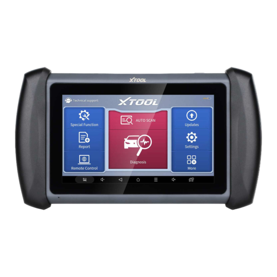
ENERAL NTRODUCTION The XTOOL IP819TP TPMS diagnosis system (referred to as the “IP819TP” in the rest of the manual) is an advanced automotive scanning tool based on the Android operating system. It supports multiple languages and is suitable for different countries and regions. The advantage of this OBD-II (On-Board Diagnostics, Gen.2) scanner is its comprehensive functions and its ability to quickly provide the user with more accurate diagnostic information. -
Page 7: Getting Started
2. G ETTING TARTED CONNECTING POWER The scan tool may need to be charged before first use. Confirm the proper power adapter (either 120 VAC North American or 240 VAC European version) is attached to the AC/DC charger. Plug the AC/DC charger into a wall outlet Plug the USB cable into the AC/DC charger and also into the scan tool’s USB charging port. - Page 8 Select a network to connect to on the Wi-Fi connection page. You need to enter the Wi-Fi password to establish Wi-Fi connectivity and the activation page, as shown in the figure below. You can also click the "Trial" button in the upper right corner to try it out before activation.
-
Page 9: Vehicle Connection
Click OK to enter the diagnostic system and start using the device. VEHICLE CONNECTION IP819TP must be connected to the vehicle’s OBD-II port so that the tablet can establish correct vehicle communication when doing diagnosis process. Please perform the following steps: ... - Page 10 Updates menu or consult the XTOOL technical service department; 5. Only wiring harnesses provided by XTOOL and designed for the scan tool are permitted to be used with this scan tool to avoid damage to the vehicle or the scan tool;...
- Page 11 To begin TPMS testing, select “TPMS” menu on the center of the main screen. The following menu allows you to select the system via those methods: Vehicle: Select the manufacturer and the model of the car and get into the menu for that specific vehicle. OEM: Choose the manufacturer and the part number of the OEM TOMS sensor and get into the menu for specific sensors.
- Page 12 ⚠ Diagnosis and relearn menu are not supported via selecting menu via OEM sensor. Please select by vehicle if necessary. Auto detect VIN: Automatically choose the manufacturer by scanning the VIN code of the vehicle. Please connect the VCI box to do so. Manually Input VIN: Automatically choose the manufacturer by recognizing the VIN code that you have manually input.
- Page 13 History: Check the vehicles that you have done before. You can also check TPMS Diagnosis Report here (see Report section for details). SELECT BY VEHICLE To select the vehicle that you are going to do TPMS diagnosis, please select the region first. Normally the region should match the area where you are in.
- Page 14 After that, select the region on the left (the region where the brand is originated) to find the manufacturer you need. Click the brand, find the model, and select the model year to continue. ⚠ Sometimes there are multiple menus with the same model year, The menu will also show the frequency and the part number of the sensor for you to recognize which one to choose.
- Page 15 SELECT BY OEM SENSOR P/N To activate and program sensors based on the OEM sensors, select “OEM” menu on the top of the screen to continue. Find the manufacturer for the sensor first, then search the correct part number for that specific sensor. ⚠...
- Page 16 Here is the screen when you select the menu by sensor P/N: Here are all the functions available on the TPMS diagnosis system. SENSOR ACTIVATION TPMS SYSTEM DIAGNOSIS XTOOL SENSOR PROGRAMMING SENSOR RELEARN ...
- Page 17 OEM/XTOOL SENSOR INFORMATION CHECK We will introduce these functions on the following parts of the manual. ⚠ Sometimes not all functions are shown on the menus. It may because of: Only activation and programming menus will be shown on the menus when you select the menu via searching by sensors.
- Page 18 The device will show the TPMS sensor ID, tire pressure, temperature and the battery status if the sensor is successfully triggered. If not, a failed sign will show up like the picture below. After activated one of the sensors, go clockwise and check other tires, and go through the entire vehicle. Sometimes there are also sensor inside the spare tire, and you can activate that if necessary.
- Page 19 XTOOL SENSOR PROGRAMMING IP819 TP can write specific IDs into XTOOL Tire Pressure Sensors before they are applied into the tires. There are several options to program the sensors, we will introduce them one by one in the following sections.
- Page 20 COPY ID BY ACTIVATION: Before doing this, make sure that you have activated all 4 sensors on the car. Do not exit, go to “Program” section and select the tire position that you want to program. Put the sensor close to the top-right corner of the device. Click “Copy by Activation” and the device will automatically scan the sensor close to the device.
- Page 21 After finding the sensor, the device will write ID into the sensor, and the S/N of the sensor will show up. When the process is done, the new ID will show up at the form on the right. Make sure it is the same as the original ID, and you are free to install it on your new tires.
- Page 22 Select the tire position that you want to install the sensor into, then put the XTOOL sensor close to the top-right corner of the device and click “Copy by OBD” . After finding the sensor, the device will write the original ID into the sensor, and the S/N of the sensor will show up.
- Page 23 WRITE ID MANUALLY: Manually write an ID into the sensor. ⚠ When you select this function, you can only write one sensor at once. Click “Copy by Input”, then input the ID that you want to write into the sensor. ⚠...
- Page 24 CREATE RANDOM ID: Automatically generate random IDs and write to the sensors. To do that, put the sensor(s) close to the right-top corner of the device and click “Auto Create” button. The device will find the sensor(s) and write random IDs into them. After the process, the ID and the S/N will show up on the screen.
- Page 25 You can also put multiple sensors close to the device and program them at the same time. Theoretically you can program up to 8 sensors at once, but we suggest you program the sensors one by one to maximize the success rate. TPMS RELEARN ...
- Page 26 When you are in the TPMS check menu, click the sensor icon on the right to get the OEM sensor info. You can also check the XTOOL sensor info on the right side. To do that, click the search icon to trigger the sensor first.
- Page 27 Put the sensor that you want to check close to the top-right corner of the device and leave other sensors away. The device will show the info for that sensor. ⚠ When finished TPMS diagnosis procedure, please exit the menu. We don’t suggest to turn off the screen when you are still inside the diagnosis menu, and if you do so, please restart the app to re-enter the diagnosis procedure.
-
Page 28: Diagnostic
Please click Diagnosis on the main menu to enter the selection menu, manually select the engine system to read the ECU information, and confirm whether the VIN can be read. Contact the XTOOL technical team to provide the VIN code to confirm whether the model supports automatic identification of VIN. - Page 29 SELECT VEHICLE BY AREA In addition to the above 3 methods, you can also choose a car brand by selecting the appropriate region at the top of the screen. You can select the vehicle model that needs to be diagnosed according to the area, as shown below: OBD-II supports reading the related fault codes of the Powertrain Control Module (PCM);...
-
Page 30: Diagnosis Functions
the vehicle in the sub-menu to diagnose the vehicle. Enter "System Selection", you can also diagnose the vehicle according to the system according to your needs after selecting the model. DIAGNOSIS FUNCTIONS Diagnostics functions supported by the scan tool are listed below: Read ECU Information ... - Page 31 In the process of diagnosis, if the device shows “System is OK” or “No Trouble Code”, it means there is no related trouble code stored in ECU or some troubles are not under the control of ECU. Most troubles are mechanical system troubles or executive circuit troubles.
- Page 32 Current DTC’s can be cleared using the Current DTC’s are trouble codes that are stored in the Clear DTC’s function of the Scantool, or ECU when both continuous and non-continuous (2 trip) Current /Present when the ECU monitor (2 trip monitor) has monitors fail.
- Page 33 Custom The scan tool includes support to select and show multiple PIDs. Click Display All to display all PIDs Combine The scan tool includes support to select multiple PIDs and click Combine to combine different graphs into one chart. Data recording ...
- Page 34 Pause Click this button to pause the recording timeline FREEZE FRAME When the signal of the sensor is abnormal, the ECU will save the data at that moment of failure to form a freeze-frame. It is usually used to analyze the reasons that may lead to component(?) failures. The live data items supported by vehicles of different brands are not the same, so the freeze frames displayed when diagnosing vehicles of different brands may also be different.
- Page 35 Context when fault appeared: record the live data when fault appeared to help the user to know the vehicle status. *Some vehicles don't support this function; users will get a prompt when they click the menu. Current context: Displays the current live data stream associated with the DTC Additional data: record other data related to the fault ACTUATION TEST (BI-DIRECTIONAL CONTROL) ...
-
Page 36: Special Functions
These functions often eliminate the need to reset codes after resolving common problems. Since XTOOL is continuously developing, the manual may not include all of the latest special functions that are available for download. This user manual lists some of the commonly used special reset services for your reference. - Page 37 When ready, click "OK" to enter the bleed procedure, and pumping the brake pedal continuously with steady applies every 2 seconds during the entire procedure...
- Page 38 Continue pumping the brake pedal, when air bubbles are no longer visible, select OK to enter next bleed procedure for left front wheel Repeat the operation 3 times to complete the bleed procedure for the left front wheel, right front wheel and right rear wheel in turn.
-
Page 39: Oil Reset
Caution The ABS pump screw needs to be unscrewed Brake fluid will be under pressure during this process. Secure the bleed hose and open bleeder screws slowly Some vehicles do not support automatic bleeding, but manually bleeding 5.2 OIL RESET The scan tool can be used to reset the engine oil life system, which calculates the optimum oil life change interval based on the vehicle’s driving conditions and climate. - Page 40 Enter Maintenance mileage reset menu. Click INPUT and enter a reasonable value of remaining oil life and press OK. Confirm the [New Value] you just entered, and then click OK at the bottom right to complete the procedure. Message of ‘Write successfully’ displays when Oil Reset function has successfully performed.
-
Page 41: Epb
5.3 EPB Electronic Parking Brake (EPB) System reset is a popular special function. You can use this function to reset the electronic parking brake system and brake pads (retraction, release of the brake pump), G-sensor and body angle calibration. This function has multiple uses and can safely and effectively maintain the electronic brake system. These applications include deactivating and activating brake control systems, assisting in controlling brake fluid, applying and releasing brake pads, setting brakes after replacing brake discs or brake pads, etc. -
Page 42: Sas
Wait until the message of ‘Successful operation’ popes up. And press OK to exit the menu. Enter the Exit maintenance mode menu and wait until the message of ‘‘Successful operation’ popes up. 5.3 SAS Steering Angle Sensors (SAS) System Calibration permanently stores the current steering wheel position as the straight- ahead position in the SAS EEPROM. -
Page 43: Bms Reset
Follow the instructions displayed and press OK after completing the instructions shown. Wait until the following instruction is displayed and press OK after completing the instructions shown. Message of ‘Function execution is completed’ displayed when SAS reset function has successfully completed. 5.5 BMS RESET The Battery Management System (BMS) allows the scan tool to evaluate the battery charge state, monitor the close-circuit current, register the battery replacement and activate the rest state of the vehicle. - Page 44 The main battery is replaced. Battery matching must be performed to clear original low battery information and prevent the related control module from detecting false information. If the related control module detects false information, it will invalidate some electric auxiliary functions, such as automatic start & stop function, sunroof without one-key trigger function or power window without automatic function.
-
Page 45: Injector Coding
5.6 INJECTOR CODING This function can write the identification code of the fuel injector into the ECU so that the ECU can recognize the new injector. After the ECU or injector is replaced, the injector code of each cylinder must be confirmed or re-coded so that the cylinder can better identify injectors to accurately control fuel injection. - Page 46 Enter the Change the value of cylinder menu of the replaced injector(s), enter the new 5-digit value, and then press OK. Wait until the message ‘Write successfully’ pops up. Turn off the ignition switch. Wait until the message asks you to turn on the ignition switch. Re-enter the Fuel injection nozzle injection volume adjustment menu to check whether the new value(s) are shown.
-
Page 47: Dpf Regeneration
5.7 DPF REGENERATION The Diesel Particle Filter (DPF) function manages DPF regeneration, DPF component replacement teach-in, and DPF teach-in after replacing the ECM. The ECM monitors driving style and selects a suitable time to employ regeneration. Vehicles driven a lot at idling speed and low load will attempt to regenerate earlier than vehicles driven more with higher load and speed. - Page 48 Read the instructions carefully and follow the instructions shown on the screen. Press OK after completing the instructions shown. Follow the instructions displayed and press OK after completing the instructions shown. IMPORTANT: Please pay attention to the Note. Press the OK button to start the regeneration.
-
Page 49: Settings
10. Wait for the value of carbon deposit to decrease until a message of ‘Emergency regeneration has been completed’ pops up, this process may take up to 40 minutes. 11. Wait for 2 minutes to let the particulate filter cool down. 12. -
Page 50: Language
How to change the language of your software? Step1: Contact your dealer or XTOOL Support and leave a message about the language you need and the S/N of your device. A technician will modify the language configuration for you in the background. Wait for a response from the technician indicating Step 1 is complete. -
Page 51: My Workshop Info
MY WORKSHOP INFO Click on My Workshop Information, you can input your workshop information here. As shown in the figure below, you need to fill in the valid information in the corresponding column and click "SUBMIT". Then it will show your workshop information in the report when you generate a diagnostic report, including your company name, address, website, telephone, and mailbox. -
Page 52: About
You can view the firmware information here, including the firmware name, the latest firmware version and the currently used firmware version. ⚠ The Diagnostic tablet supports automatic firmware update, please make sure that the device is connected to the network when you enter the diagnostic software and the firmware will be automatically updated to the latest version. ABOUT Tap on ABOUT, you can check the serial number and APP version on here. - Page 53 Press and hold each item to delete the selected reports. If you want to resume the diagnostic progress, click the button on the right to go back to diagnostic menu, with all recorded data saved inside (activated ID, ECU ID…).
-
Page 54: Report
DIAGNOSTICS REPORTS & DATA REPLAY Diagnostic Report is used for viewing and printing the saved files, such as Live Data, Trouble codes or pictures generated in the process of diagnosis. Users also can view a record of which cars have been previously tested. It includes 3 parts: Diagnosis Report ... - Page 55 Please follow the below steps to print your report▼ Step 1: Install an APP that can connect to your target printer. Add the printer and input the IP address of the printer in the APP, or you can contact the XTOOL support team (support1 / support2@xtooltech.com) for help.
-
Page 56: Replay
⚠ The Scan tool doesn’t provide the printer driver software, please install a third part App on the tablet if you need the print your Diagnostic report. Step 2: On the Android main menu, go to Settings -> Printing-> Turn printer on. Step 3: Report->... -
Page 57: Update & Factory Reset
Internet. To access the update application, open the Diagnostic application and click Updates to enter the screen shown below: ⚠ After contacting your XTOOL Support to change the language configuration, you need to download all the software packages on the device again. - Page 58 After selecting the system language, click Next to enter the Wi-Fi connection page, as shown below: Select a network to connect to on the Wi-Fi connection page. You will need to enter the Wi-Fi password to establish Wi- Fi connectivity. After successfully connecting to an Internet network connection, the scan tool will jump to Factory mode to download the software: This download process can take several minutes, largely determined by the speed of your Internet connection.
-
Page 59: Faq
Q2: HOW TO PRINT A DIAGNOSTIC REPORT The XTOOL device is compatible with third-party print drivers. You can download the printer driver you need in the browser that comes with the tablet to install it, and then set your printer in the OS settings. After the configuration is completed, you can print Reports. -
Page 60: Q5: How To Make An Appointment For Remote Support
The tablet has to connect to the network every 30 days, otherwise, the Diagnostic app will be locked and disabled until the device is connected to the network. After connecting to the network, the APP will be available again. If the device is still unavailable, please contact XTOOL technical support team for help. -
Page 61: Q12: Can't Receive The Email After Sharing The Diagnostic Report
TeamViewer program (http://www.teamviewer.com) online, and then start the software on their computer at the same time, to provide support and remote control of the tablet. 4. Provide your ID to the partner or XTOOL technician, and then wait for them to send you a remote-control request. - Page 62 5. A pop-up window will be displayed, asking you to permit the remote-control program to control your device. 6. Click Allow to accept, or click Reject to reject.
-
Page 63: Appendix
This manual is designed for the usage of the IP819 Smart Diagnostic System and provides operating instructions and product descriptions for users of this scan tool. Use the device only as described in this manual. XTOOL is not responsible for any consequences of violating the laws and regulations caused by using the product or its data information. -
Page 64: Navigation Buttons
Special Functions for diagnostics View Vehicle diagnostic reports Remote Control: This function allows someone to remotely view the tablet screen and also issue commands to the tablet over the Internet. This function is helpful when consulting with a colleague about a particular set of scan tool readings. Updates: Once the scan tool is connected to a Wi-Fi Internet connection, any available software updates are identified on this icon. -
Page 66: Compliance Information
COMPLIANCE INFORMATION FCC COMPLIANCE FCC ID: 2AW3IP710 This device complies with Part 15 of the FCC Rules. Operation is subject to the following two conditions: This device may not cause harmful interference This device must accept any interference received, including interference that may cause undesired operation. Warning Changes or modifications not expressly approved by the party responsible for compliance could void the user’s authority to operate the equipment. - Page 67 SHENZHEN XTOOLTECH INTELLIGENT CO., LTD COMPANY ADDRESS: 17&18/F, BUILDING A2, CREATIVITY CITY, LIUXIAN AVENUE, NANSHAN DISTRICT, SHENZHEN, CHINA FACTORY ADDRESS: 2/F, BUILDING 12, TANGTOU THIRD INDUSTRIAL ZONE, SHIYAN STREET, BAOAN DISTRICT, SHENZHEN, CHINA SERVICE-HOTLINE: 0086-755-21670995/86267858 EMAIL: MARKETING@XTOOLTECH.COM FAX: 0755-83461644 WEBSITE: WWW.XTOOLTECH.COM...
Need help?
Do you have a question about the IP819TP and is the answer not in the manual?
Questions and answers