Advertisement
Quick Links
Advertisement

Subscribe to Our Youtube Channel
Related Manuals for fantastic furniture Vior


Summary of Contents for fantastic furniture Vior
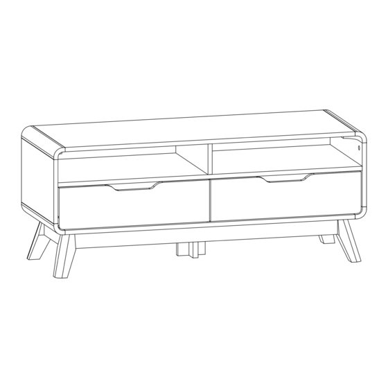
- Page 1 Version 1.0 Vior Two People Lowline Small 1100mm fantasticfurniture.com.au Required...
- Page 2 We’re thrilled you’ve chosen Fantastic Furniture to help create a home you’ll love! Love it? Share it! Fantastic buy! Share how it looks at home on Instagram for you chance to win a $250 Fantastic Furniture Gift Card! @fantasticfurniture fantasticfurniture.com.au Page 2...
-
Page 3: Assembly Checklist
Assembly Checklist Read through the instructions carefully Make sure you have all the required tools. before you begin. Never use power tools unless instructed. Unless instructed, do not fully tighten Identify and lay out all of the screws until the item is fully assembled. components before you begin assembly. - Page 4 What you need to assemble the product Othe tools you need Flat head screwdriver; Phillips head Top Panel (P1) screwdriver; Mallet Right Side Panel Upper Divider (P3) Panel (P8) Left Side Panel (P2) Shelf (P10) Back Panel (P20) Lower Divider Panel (P9) Bottom Panel (P4) Leg (P5)
- Page 5 Hardware Pack 44 x Dowels 21 x Long Screws 12 x Small Cam 55 x Cam Bolts 43 x Big Cam (H3) 38mm (H5) Nuts (H4) (H1) Nuts (H2) 4 x Felt Pads 1 x Adjustable 24 x Screws 4 x Slides 4 x Long Screws (H8) Foot (H10)
- Page 6 Step 1 You will need 13 x Cam Bolts Phillips Head (P4) (H1) Screwdriver Screw 13 x Cam Bolts (H1) into Bottom Panel (P4) as shown, tighten with a Phillips Head Screwdriver. Step 2 (P6) (P6) You will need 14 x Dowels Mallet (H3) (P7)
- Page 7 Step 3 You will need 8 x Cam Bolts Phillips Head (H1) Screwdriver (P5) 4 x Felt Pads (H8) Screw 2 x Cam Bolts (H1) into each Leg (P5) using a Phillips Head Screwdriver. Attach 1 x Felt Pad (H8) onto each Leg (P5) as shown. This is how a cam nut works..
- Page 8 Step 5 (P5) You will need (P5) 4 x Big Cam Flat Head Nuts (H2) Screwdriver (P7) (P7) (P5) (P5) Position 2 x Long Rails (P7) between the assembled units as shown. Insert 4 x Big Cam Nuts (H2) into Long Rails (P7), using a Flat Head Screwdriver turn clockwise to lock.
- Page 9 Step 7 (P19) (P18) You will need 2 x Dowels Phillips Head (H3) Screwdriver 1 x Long Screw 38mm (H5) (P18) (P19) Insert 2 x Dowels (H3) into Small Middle Leg (P19) and Big Middle Leg (P18). Attach Small Middle Leg (P19) to Big Middle Leg (P18) with 1 x Long Screw (H5), tighten with a Phillips Head Screwdriver.
- Page 10 Step 9 You will need 4 x Cam Bolts Phillips Head (H1) Screwdriver (P4) 4 x Long Screws 38mm (H9) Screw 4 x Cam Bolts (H1) into Bottom Panel (P4) as shown, tighten with a Phillips Head Screwdriver. Screw 4 x Long Screws (H9) into Bottom Panel (P4), tighten with a Phillips Head Screwdriver. Step 10 You will need 6 x Cam Bolts...
- Page 11 Step 11 You will need (P8) 4 x Cam Bolts 16 x Dowels (H1) (H3) Phillips Head Mallet Screwdriver (P20) (P10) Insert 4 x Dowels (H3) into Upper Divider Panel (P8) as shown. Insert 8 x Dowels (H3) into Back Panel (P20) as shown. Insert 4 x Dowels (H3) into Shelf (P10) as shown.
- Page 12 Step 12 Separate the 4 sets of Slide Runners (H7-2) and Slide Tracks (H7-1) from Slides (H7) by following the steps below: You will need Extend the Slide Runner all the way forward. Press the plastic release lever of the Slide down and pull the Slide Runner (H7-2) completely out.
- Page 13 Step 13 H7-1 H7-1 Note the position of the rubber stopper You will need Second hole H7-1 from back Laminated 6 x Screws 4 x Dowels edge 12mm (H6) (H3) Phillips Head Mallet Screwdriver (P9) (P9) Note the screw fixing hole is di erent to 2 x Slide Tracks (H7-1)
- Page 14 Step 15 These hole are facing up You will need (P9) (P20) Phillips Head 2 x Long Screws 38mm (H5) Screwdriver Round corner Attach Lower Divider Panel (P9) to Back Panel (P20) with 2 x Long Screws (H5) using a Phillips Head Screwdriver as shown. Two People Step 16 You will need...
- Page 15 Step 17 You will need (P2) H2 Flat Head (P10) Screwdriver (P20) Position Left Side Panel (P2) to assembled unit as shown. Insert 4 x Big Cam Nuts (H2) into Panels (P10) & (P20). Turn clockwise to lock using a Flat Head Screwdriver. Step 18 (P3) You will need...
- Page 16 Two People Step 19 You will need (P3) Required Flat Head Screwdriver (P2) (P20) (P4) Position assembled unit onto Bottom Panel (P4) as shown. Insert 4 x Big Cam Nuts (H2) into Panels (P2) & (P3), turn clockwise to lock using a Flat Head Screwdriver.
- Page 17 Step 21 Two People You will need (P1) Required Flat Head Screwdriver (P3) (P8) (P2) Position Top Panel (P1) to assembled unit as shown. Insert 6 x Big Cam Nuts (H2) into Panels (P2), (P3) & (P8), turn clockwise to lock using a Flat Head Screwdriver. Step 22 You will need (P16)
- Page 18 Step 23 You will need (P15) (P11) Flat Head (P15) Screwdriver (P11) (P12) (P12) (P16) (P17) Position both Drawer Sides (P11), (P12) and Drawer Rail (P15) onto Drawer Fronts (P16) and (P17). Insert 12 x Small Cam Nuts (H4) into Drawer Sides (P11), (P12) and Drawer Rails (P15). Turn Small Cam Nuts to lock using a Flat Head Screwdriver.
- Page 19 Step 25 Ensure the pre-drilled holes on the side of Drawer Left & Right (P11, P12) align with holes on drawer back (P13), You will need and the holes on drawer back (P13) align with the holes on drawer rails (P15). (P11) Phillips Head Screwdriver...
- Page 20 Step 27 (P17) (P16) Move inner ball bearing track to front of Slide Track (H7-1). Gently insert Drawer Slide Runner into ball bearing Track. H7-2 H7-1 Position drawer so that the Slide Runners (H7-2) align with Slide Tracks (H7-1) as shown. Gently push drawer into the closed position.
-
Page 21: Job Complete
Step 28 Job complete! In the interest of our environment please dispose of all packaging thoughtfully. fantasticfurniture.com.au Page 21...
Need help?
Do you have a question about the Vior and is the answer not in the manual?
Questions and answers