Table of Contents
Advertisement
Quick Links
Assembly Instructions
VISION
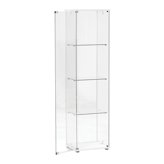
Display Cabinet
Tempered Glass SHOULD ALWAYS BE
HANDLED WITH CARE
Ver:1.1
Advertisement
Table of Contents

Related Manuals for fantastic furniture VISION


Summary of Contents for fantastic furniture VISION
- Page 1 Assembly Instructions VISION Display Cabinet TEMPERED GLASS SHOULD ALWAYS BE HANDLED WITH CARE Ver:1.1...
- Page 2 Lay out all of the components on a soft surface as if you were preparing to do a jigsaw puzzle. Read Instructions carefully. Check no parts are missing Separate and identify each component from the Carefully identify each component, especially hardware pack and rest each one in its proper those that are similar.
- Page 3 As wall materials vary, screws for fixing to wall are not included. For advice on suitable screw systems, contact your local specialised dealer. TEMPERED GLASS should be handled with care. Scratches, chips, sudden changes in temperature, hairline fractures or other minor impurities may cause the glass to break suddenly and without warning.
- Page 4 What You Need Joiner strip Joiner Strip (P3) (P3) Top (P5) Back (P2) Side Panel (Tools are not provided) Shelf (P7) (P4) Phillips screwdriver Door (P6) Shelf (P7) Shelf (P7) Base (P1) Side Panel (P4) 4 x Front brackets 8 x M3 x 13 mm Screws 12 x Bolts 4 x Rear Corner Brackets (H2)
- Page 5 Step 1 You will need: 4x M4 x 22 mm Screws (H6) 4 x 20 x 44 mm Feet Base (H5) (P1) Attach Feet (H5) to Base (P1) using 4 x Screws (H6) and tighten using phillips head screwdriver. Turn the Base (P1) to let it stand on its feet. Step 2 Back (P2)
- Page 6 Step 3 Strip Joiner (P3) Back (P2) Base (P1) With the help of another person, attach 2x Strip Joiners (P3) to the sides of Back Panel (P2). Step 4 Side Panel Side Panel (P4) (P4) Base (P1) Insert one short edge of Side Panel (P4) into the groove of Base (P1) and the adjacent long edge into the Strip Joiner (P3).
- Page 7 Step 5 Top (P5) Side Panel Side (P4) Panel (P4) Back (P2) Place Top (P5) so that the top edges of the two Side Panels (P4) and Back (P2) are in the grooves of Top (P5) Step 6 Top (P5) You will need: Rear Corner Brackets (H1)
- Page 8 Step 7 Top (P5) You will need: 12 x Shelf lugs (H7) Back (P2) Side Side Magnetic Catch Panel Panel (P4) (H9) (P4) Base (P1) Note: This installs the door to open from the left. To install the door to open from the right, install the Catch (H9) on the right side. Insert a magnetic catch (H9) each into the top (P5) and Base (P1).
- Page 9 Step 9 You will need: Sleeve (H15) Note: Door This installs the door to open from the left. (P6) If you have set up the magnetic catches in step 7 to open from the right, please install the door from the left side. Insert a Sleeve (H15) each into the Top (P5) and Base (P1).
- Page 10 Step 11 Shelf (P7) Shelf (P7) Shelf (P7) Carefully move each Shelf (P7) into the cabinet above the lugs. Place each Shelf (P7) onto the lugs, making sure it sits firmly on all four lugs. Step 12 You will need: Wall Strap (H12) Washer...
- Page 11 Step You will need: 1x M4 x 14 mm Screws (H13) Washer (H14) Reposition the cabinet. Attach the cabinet at its top to the wall strap (H12) using 1 x screw (H13) and washer (H14). Step The job is now complete! In the interest of our environment Please dispose of all packaging thoughtfully.
Need help?
Do you have a question about the VISION and is the answer not in the manual?
Questions and answers