Table of Contents
Advertisement
Quick Links
Advertisement
Table of Contents

Subscribe to Our Youtube Channel
Related Manuals for KSB COBRA-TDC01/03


Summary of Contents for KSB COBRA-TDC01/03
- Page 1 Tilting Disc Check Valve COBRA-TDC01/03 Installation/Operating Manual...
- Page 2 All rights reserved. The contents provided herein must neither be distributed, copied, reproduced, edited or processed for any other purpose, nor otherwise transmitted, published or made available to a third party without the manufacturer's express written consent. Subject to technical modification without prior notice. © KSB SE & Co. KGaA, Frankenthal 18/08/2022...
-
Page 3: Table Of Contents
Flange connection.......................... 17 Insulation ................................ 17 Commissioning/Start-up/Shutdown.................... 18 Commissioning.............................. 18 6.1.1 Prerequisites for commissioning/start-up .................. 18 6.1.2 Functional test............................ 18 Operating limits.............................. 18 6.2.1 Pressure/temperature ratings...................... 19 6.2.2 Flow velocity............................ 19 Shutdown................................ 20 6.3.1 Measures to be taken for shutdown .................... 20 Returning to service ............................ 20 COBRA-TDC01/03 3 of 32... - Page 4 7.2.4 Assembling the valve ......................... 23 7.2.5 Tightening torques .......................... 24 Trouble-shooting.......................... 25 Related Documents .......................... 26 General assembly drawing with list of components COBRA-TDC01 ............ 26 General assembly drawing with list of components COBRA-TDC03 ............ 27 Index .............................. 29 COBRA-TDC01/03 4 of 32...
-
Page 5: Glossary
Glossary Glossary Nominal pressure; a characteristic upon which standards regarding piping, piping components, valves, etc., are based COBRA-TDC01/03 5 of 32... -
Page 6: General
Conditions which need to be fulfilled before proceeding with the step-by-step instructions ⊳ Safety instructions ⇨ Result of an action Cross-references ⇨ Step-by-step instructions Note Recommendations and important information on how to handle the product If included in agreed scope of supply COBRA-TDC01/03 6 of 32... -
Page 7: Key To Safety Symbols/Markings
In conjunction with one of the signal words this symbol indicates a hazard involving electrical voltage and identifies information about protection against electrical voltage. Machine damage In conjunction with the signal word CAUTION this symbol indicates a hazard for the machine and its functions. COBRA-TDC01/03 7 of 32... -
Page 8: Safety
Consult the manufacturer if the valve is subjected to dynamic loads or any other additional influences. ▪ Consult the manufacturer about any other modes of operation not described in the product literature. ▪ Do not use the valve as a foothold. COBRA-TDC01/03 8 of 32... -
Page 9: Prevention Of Foreseeable Misuse
▪ Eliminate all electrical hazards. (In this respect refer to the applicable national safety regulations and/or regulations issued by the local energy supply companies.) ▪ Take protective measures against the impact of potentially occurring surge pressure (e.g. bursting discs). COBRA-TDC01/03 9 of 32... -
Page 10: Safety Information For Maintenance, Inspection And Installation
2.8 Unauthorised modes of operation ▪ The valve is operated outside the limits stated in the operating manual. ▪ The valve is not operated in accordance with the intended use. (ð Section 2.2, Page 8) COBRA-TDC01/03 10 of 32... -
Page 11: Transport/Storage/Disposal
Fig. 1: Transporting the valve 1. Suspend the valve from the lifting equipment and transport it. 3.3 Storage/preservation If commissioning is to take place some time after delivery, we recommend that the following measures be taken for storing the valve: COBRA-TDC01/03 11 of 32... -
Page 12: Return To Supplier
Collect greases and other lubricants during dismantling. 2. Separate and sort the valve materials, e.g. by: - Metals - Plastics - Electronic waste - Greases and other lubricants 3. Dispose of materials in accordance with local regulations or in another controlled manner. COBRA-TDC01/03 12 of 32... -
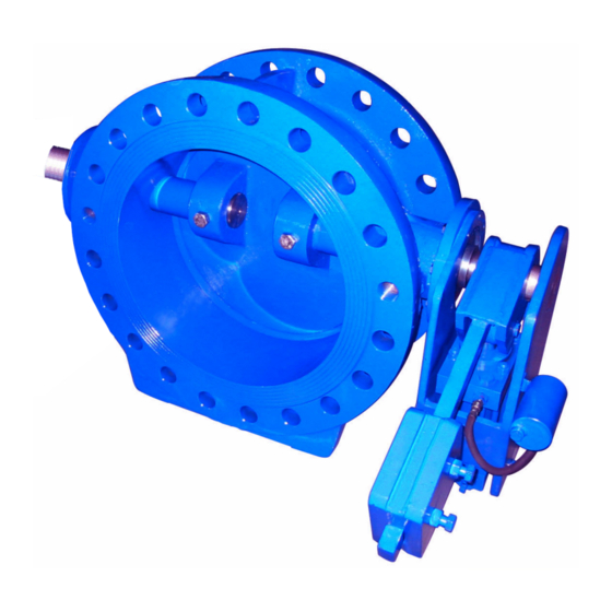
Page 13: Description Of The Valve
▪ With counterweight, or with counterweight with hydraulic damper ▪ Epoxy-coated body ▪ Valve certified for drinking water applications to WRAS (elastomer and coating) Variants ▪ Smaller nominal sizes from DN 80 (only after technical evaluation) ▪ NBR gasket ▪ Counterweight for vertical installation COBRA-TDC01/03 13 of 32... -
Page 14: Function
80 dB in acc. with IEC 60534-8-4. Unfavourable piping layouts or off- design operating conditions may give rise to physical phenomena like cavitation, resulting in significantly higher sound pressure levels. COBRA-TDC01/03 14 of 32... -
Page 15: Installation At Site
The valves should preferably be installed in horizontal pipes. When installing them in vertical pipes, make sure that the flow direction is upward. In the unpressurised condition, the valve disc will then be closed by its own weight. Fig. 2: Vertical and horizontal installation position of COBRA-TDC01/03 DANGER Dead-end valve... -
Page 16: Preparing The Valve
▷ Connect the pipes to the valve without transmitting any stresses or strains. ▷ Take structural measures to prevent any piping forces from being transmitted to the valve. ▷ Avoid mechanical loads beyond normal levels, e.g. piping forces, moments and vibrations. COBRA-TDC01/03 16 of 32... -
Page 17: Flange Connection
5.5 Insulation WARNING Cold/hot piping and/or valve Risk of thermal injury! ▷ Insulate the valve. ▷ Fit warning signs. For any insulation fitted on the valve observe the following: ▪ The valve's function must not be impaired. COBRA-TDC01/03 17 of 32... -
Page 18: Commissioning/Start-Up/Shutdown
▪ The material's chemical resistance and stability under load have been checked. 6.1.2 Functional test The following functions must be checked: 1. Check the shut-off function of the installed valve prior to commissioning/start- up by opening and closing the valve several times. 6.2 Operating limits COBRA-TDC01/03 18 of 32... -
Page 19: Pressure/Temperature Ratings
6.2.1 Pressure/temperature ratings Table 5: Permissible operating pressure [bar] Material [°C] -10 to 120 EN-GJS-400-15 15,5 14,7 13,9 12,8 11,2 24,3 21,8 17,5 38,8 36,8 34,8 6.2.2 Flow velocity Table 6: Permissible flow velocity with the valve fully open [m/s] COBRA-TDC01/03 19 of 32... -
Page 20: Shutdown
6.4 Returning to service For returning the equipment to service, observe the sections on commissioning/start- up and the operating limits (ð Section 6.2, Page 18) . In addition, carry out all servicing/maintenance operations before returning the valve to service. (ð Section 7, Page 21) COBRA-TDC01/03 20 of 32... -
Page 21: Servicing/Maintenance
NOTE All maintenance work, service work and installation work can be carried out by KSB Service or authorised workshops. For contact details refer to the enclosed "Addresses" booklet or visit "www.ksb.com/contact" on the Internet. -
Page 22: Inspection Work
ü The valve has been disconnected from the pipe on one side at least. 1. Fully open valve disc 2. 2. Loosen retaining ring 3. 3. Undo nuts and bolts 11 (COBRA-TDC01) or 14 (COBRA-TDC03). 4. Remove and clean gasket 7 (COBRA-TDC01) or 10 (COBRA-TDC03) and retaining ring 3. COBRA-TDC01/03 22 of 32... -
Page 23: Assembling The Valve
2. Fit front cover 6 (COBRA-TDC01) or 8 (COBRA-TDC03) and rear cover 9. 3. Tighten bolts 12 and 15 (COBRA-TDC01) or 15 and 18 (COBRA-TDC03). (ð Section 7.2.5, Page 24) 4. Fit the counterweight or hydraulic damper. 5. Check the position of the valve disc and the position indicator. COBRA-TDC01/03 23 of 32... -
Page 24: Tightening Torques
7 Servicing/Maintenance 7.2.5 Tightening torques Table 7: Tightening torques of bolts/screws for valve disc sealing element [Nm] Thread size Tightening torque Table 8: Tightening torques of bonnet/cover bolts [Nm] Thread size Tightening torque COBRA-TDC01/03 24 of 32... -
Page 25: Trouble-Shooting
Replace body; check for water hammer. High actuating forces Deposits at valve seat Flush valve, dismantle, if necessary, and clean seat area. Dry piping environment, i.e. valve is Verify contact with fluid handled. not in contact with fluid handled. COBRA-TDC01/03 25 of 32... -
Page 26: Related Documents
AISI 420 Hinge pin bearing G-CuSn10 Front cover St-37 Epoxy-coated Joint ring EPDM 65-70 Shore O-ring EPDM 65-70 Shore Rear cover St-37 Epoxy-coated Ck 45 Bolt/screw Bolt/screw Setting screw Circlip Ck 60 Setting screw Setting screw Lever COBRA-TDC01/03 26 of 32... -
Page 27: General Assembly Drawing With List Of Components Cobra-Tdc03
AISI 420 Rear hinge pin AISI 420 Hinge pin bearing G-CuSn10 Spacer bush Delrin Front cover St-37 Epoxy-coated Rear cover St-37 Epoxy-coated Joint ring EPDM 65-70 Shore O-ring EPDM 65-70 Shore O-ring EPDM 65-70 Shore Ck 45 COBRA-TDC01/03 27 of 32... - Page 28 9 Related Documents Part No. Description Material Note Bolt/screw Bolt/screw Setting screw Circlip Ck 60 Setting screw Setting screw Bolt/screw Washer Counterweight Hydraulic damper Body seat AISI 309L COBRA-TDC01/03 28 of 32...
-
Page 29: Index
Intended use 8 Key to safety symbols/markings 7 Maintenance 21 Marking 13 Materials COBRA-TDC01 26 COBRA-TDC03 27 Noise characteristic 14 Operating limits 8 Other applicable documents 6 Piping 16 Preservation 12 Product description 13 Removing the O-ring 23 Removing the valve disc sealing element 22 Return to supplier 12 Returning to service 20 COBRA-TDC01/03 29 of 32... - Page 32 KSB SE & Co. KGaA Johann-Klein-Straße 9 • 67227 Frankenthal (Germany) Tel. +49 6233 86-0 www.ksb.com KSB Italia S.p.A. Via Massimo D’Azeglio, 32 20863 Concorezzo MB Tel. +39 039 6048-000 – Fax +39 039 6048-097 www.ksb.com Centri Service Concorezzo MB • Via Massimo D’Azeglio, 32 Tel.
Need help?
Do you have a question about the COBRA-TDC01/03 and is the answer not in the manual?
Questions and answers