KSB LevelControl Basic 2 Supplementary Operating Manual
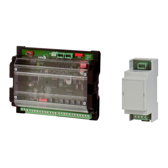
Signalling module, current measuring module, level control unit
Hide thumbs
Also See for LevelControl Basic 2:
- Supplementary operating manual (8 pages) ,
- Booklet (38 pages) ,
- Installation & operating manual (84 pages)

Related Manuals for KSB LevelControl Basic 2


Summary of Contents for KSB LevelControl Basic 2
- Page 1 Level Control Unit LevelControl Basic 2 Signalling Module Current Measuring Module Supplementary Operating Manual...
- Page 2 All rights reserved. The contents provided herein must neither be distributed, copied, reproduced, edited or processed for any other purpose, nor otherwise transmitted, published or made available to a third party without the manufacturer's express written consent. Subject to technical modification without prior notice. © KSB SE & Co. KGaA, Frankenthal 19/01/2018...
-
Page 3: Table Of Contents
10.1.1 Individual signals - control board display (example) ............... 30 10.1.2 Analog output............................ 30 10.1.3 Three-phase current measurement.................... 31 10.1.4 Single-phase current measurement .................... 32 10.1.5 Field bus connection .......................... 32 10.1.6 Redundant pneumatic level measurement .................. 33 10.1.7 Partially redundant bubbler system.................... 35 Index .............................. 37 LevelControl Basic 2 3 of 40... -
Page 4: General
This supplementary operating manual accompanies the installation/operating manual. All information contained in the installation/operating manual must be observed. Table 1: Relevant operating manuals Type series Reference number of the installation/operating manual LevelControl Basic 2 4041.80 LevelControl Basic 2 4 of 40... -
Page 5: Safety
The contents of this supplementary operating manual must be available to the specialist personnel at the site at all times. The operator is responsible for ensuring compliance with all local regulations which are not taken into account in this supplementary operating manual. LevelControl Basic 2 5 of 40... -
Page 6: Transport/Temporary Storage/Disposal
(as far as this is possible). ▪ Prevent excessive fluctuations in atmospheric humidity (see table "Ambient conditions for storage"). If stored properly, the accessories will be protected for a maximum of 12 months. LevelControl Basic 2 6 of 40... -
Page 7: Description
4 Description 4.1 Compatibility NOTE The KSB Service Tool can be downloaded free-of-charge from the KSB web site. The web site also contains further information on how to order the additional parameterisation cable required. Signalling module and current measuring module can be used with device firmware version 1.2 or higher. - Page 8 Up to 10 A, the pump current is measured directly, over 10 A, it is measured via an upstream current transformer. The current measuring module is connected to LevelControl Basic 2 via the signalling module. LevelControl Basic 2...
-
Page 9: Technical Data
(ð Section 10.1, Page 30) 4.3 Technical data Signalling module Table 3: Technical data Characteristic Value Power supply 9–30 V DC via LevelControl Basic 2 Enclosure BC version: IP00 BS version: IP20 Switching capacity of individual signals 30 V, 1 A Analog output 0/4-20 mA... - Page 10 The signalling module can be used with device firmware version 1.2 or higher. Current measuring module NOTE LevelControl Basic 2 is only fitted with current measuring module(s) ex works. Current measuring modules cannot be retrofitted! The current measuring modules are connected to LevelControl Basic 2 via the signalling module.
-
Page 11: Installation At Site
3. Carefully detach the BC PCB cover plate from the spacers. 4. Connect the signalling module to the BC PCB using the connection cable supplied. Make sure the connector is correctly positioned! When attaching the connection cable, observe the mechanical coding on the connectors! LevelControl Basic 2 11 of 40... - Page 12 If the green status LED on the signalling module flashes, the signalling module has not been detected by LevelControl Basic 2. In this case, check the firmware version of the control unit, which is displayed at parameter 4-1-1. Firmware version 1.2 or higher is required.
-
Page 13: Connecting The Current Measuring Module
If the green status LED on the signalling module flashes, the signalling module has not been detected by LevelControl Basic 2. In this case, check the firmware version of the control unit, which is displayed at parameter 4-1-1. Firmware version 1.2 or higher is required. - Page 14 5 Installation at Site Connect the current measuring module in accordance with the wiring diagram. (ð Section 10.1.3, Page 31) / (ð Section 10.1.4, Page 32) LevelControl Basic 2 14 of 40...
-
Page 15: Commissioning/Start-Up/Shutdown
4. Close the control unit again. Long-term shutdown 1. Set the manual-0-automatic switches for both pumps to "0". 2. Switch off the power supply. LevelControl Basic 2 15 of 40... - Page 16 6 Commissioning/Start-up/Shutdown ð This disables all control and signalling functions. LevelControl Basic 2 16 of 40...
-
Page 17: Operation
- A17 - Signalling module fault 7.1.2 Additional functions 7.1.2.1 Volt-free signals If the signalling module is used, six volt-free signals are provided: ▪ Switching capacity: 30 V, 1 A ▪ Type: Change-over contact. LevelControl Basic 2 17 of 40... - Page 18 Fault pump 2 Pump 2 is blocked due to a fault and cannot be started upon de-energised demand. Pump 1 operational No fault at pump 1, the manual-0-automatic switch is in "Auto" energised position LevelControl Basic 2 18 of 40...
- Page 19 7.1.2.2.1 Level measurement using float switches or digital sensors When digital level measuring methods are employed (floats, digital switches), a step signal corresponding to the switching status is displayed. The allocation of the switching states is shown in the table below: LevelControl Basic 2 19 of 40...
- Page 20 4 mA Pumps OFF Peak load pump ON 7 mA Peak load pump OFF Base load pump ON (irrelevant) Medium 10 mA High 13 mA Base load pump ON Peak load pump OFF (irrelevant) LevelControl Basic 2 20 of 40...
- Page 21 4 to 20 mA, depending on the measuring range of the pressure sensor used in the signalling module. LevelControl Basic 2 21 of 40...
- Page 22 On control units for lifting units of the MiniCompacta/Compacta series, the analog output provides a level-proportional current signal, i.e. the values measured in the range of 0 to 1 mlc are converted into output currents from 4 to 20 mA, regardless of any settings made. LevelControl Basic 2 22 of 40...
- Page 23 If a pump that represents a potential ignition source in a potentially explosive atmosphere can no longer be guaranteed to be sufficiently submerged, all running pumps will be stopped. In the event of a fault, message "A11 – Sensor fault" is output. LevelControl Basic 2 23 of 40...
- Page 24 7 Operation 7.1.2.3 Field bus connection The extension module for LevelControl Basic 2 offers a Modbus-(RTU) interface which is galvanically isolated from the control unit. The ModBus interface can be used directly for integration into a ModBus network and provides the option of connecting corresponding field bus gateways.
- Page 25 Bit 9 - A10 - External alarm External alarm – Device at the external input has been triggered Bit 10 - A11 - Sensor fault Sensor fault (float switch fault, broken wire, short circuit) LevelControl Basic 2 25 of 40...
- Page 26 If the signalling module is not the end device, remove the terminating resistors. If LevelControl Basic 2 is operated as the end device in the field bus system or if a point-to-point connection with a field bus gateway is made, the terminating resistors must be set on the PCB in order to guarantee correct operation.
- Page 27 Fig. 9: DIL switch S1 Table 18: DIL switch assignment DIL switch Connection Description Factory setting ModBus RTU RS485 termination RS485 termination Galvanically isolated GND (connecting RS485 GND with common GND) System bus CAN termination CAN termination Not used LevelControl Basic 2 27 of 40...
-
Page 28: Servicing/Maintenance
Inspection Maintenance Read the supplementary operating manual and the installation/operating manual Check cable connection between signalling module and LevelControl Basic 2 PCB for correct installation Check cable connection between current measuring module and signalling module for correct installation Re-tighten connection terminals (individual... -
Page 29: Trouble-Shooting
▪ Reset control unit Incorrect parameter settings Undocumented parameters can also be ▪ Restore parameter settings after field bus access changed via field bus ▪ Check script for field bus access and correct LevelControl Basic 2 29 of 40... -
Page 30: Related Documents
The assignment of the signal relays can be altered using the service tool. 10.1.2 Analog output Fig. 11: Analog output NOTE The analog output provides a level-proportional 4–20 mA signal. The assignment can be altered using the service tool. LevelControl Basic 2 30 of 40... -
Page 31: Three-Phase Current Measurement
Power supply to pump 1 Power supply to pump 2 Pump 1 current measuring module Pump 2 current measuring module Pump 1 current measurement connection to Pump 2 current measurement connection to signalling module signalling module LevelControl Basic 2 31 of 40... -
Page 32: Single-Phase Current Measurement
Pump 1 current measuring module Pump 2 current measuring module Pump 1 current measurement connection to Pump 2 current measurement connection to signalling module signalling module 10.1.5 Field bus connection Fig. 14: Field bus connection LevelControl Basic 2 32 of 40... -
Page 33: Redundant Pneumatic Level Measurement
The use of a redundant pneumatic system (without compressor) offers redundant level measurement and also, when ATEX mode is activated, redundant minimum level monitoring. Fig. 15: Redundant pneumatic level measurement LevelControl Basic 2 pressure sensor Redundant pressure sensor on signalling module Reducer... - Page 34 Tubes which are too long must be cut to length during installation. LevelControl Basic 2 34 of 40...
-
Page 35: Partially Redundant Bubbler System
If the compressor fails due to a fault, both level measurement systems continue to operate as redundant pneumatic level measurement systems (without compressor). Fig. 16: Partially redundant bubbler system LevelControl Basic 2 pressure sensor Redundant pressure sensor on signalling module Compressor for bubbler system... - Page 36 Tubes which are too long must be cut to length during installation. LevelControl Basic 2 36 of 40...
-
Page 37: Index
Index Index Analog output 19 Commissioning/start-up 15 Faults 29 Field bus connection 24 Individual signals 9 Inspection 28 Installation 11 Maintenance 28 Measured values menu 17 Menu extension 17 ModBus 24 Redundant level measurement 23, 33 Settings menu 17 Shutdown 15 Storage 6 Transport 6 LevelControl Basic 2 37 of 40... - Page 40 KSB SE & Co. KGaA Johann-Klein-Straße 9 • 67227 Frankenthal (Germany) Tel. +49 6233 86-0 www.ksb.com...
Need help?
Do you have a question about the LevelControl Basic 2 and is the answer not in the manual?
Questions and answers