Table of Contents
Advertisement
Available languages
Available languages
Quick Links
Advertisement
Table of Contents

Related Manuals for Soozier A90-065


Summary of Contents for Soozier A90-065
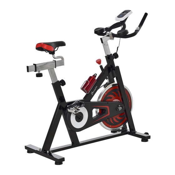
- Page 1 USER MANUAL A90-065...
- Page 3 Safety Precautions – Please Read the Instruction before Using! Assembly this product properly using original parts according to the installation instruction. Before assembly, inspect whether packages are in good condition and whether spare parts are complete in accordance with transport precautions and the list of spare parts.
-
Page 4: Part List
PART LIST SIZE SIZE DESCRIPTION DESCRIPTION main frame flat wahser ø 10 front stabilizer nylon nut rear stabilizer bearing 6004 seat post decoration cover seat bar bolt st4.2x20 front post bolt st4.2x12 handlebar bolt st4.2x10 flywheel Computer cable chain cover m5x12 belt bottle holder... - Page 5 ASSEMBLY INSTRUCTIONS STEP 1 SECURE FRONT STABILIZER (2) TO MAIN FRAME (1) AND FIX IT WITH CARRIAGE BOLTS (26), WASHERS (27), AND DOME NUTS (29). STEP 2 SECURE REAR STABILIZER (3) TO MAIN FRAME (1) AND FIX IT WITH CARRIAGE BOLTS (43), WASHERS (44), AND DOME NUTS (45).
- Page 6 STEP 5. SECURELY FIX THE SEAT(64) TO THE SEAT BAR(5). SLIDE THE SEAT BAR(5) INTO THE SEAT POST(4) AND TIGHTEN THE SPRING KNOB(52) TO SECURE TEP6. FIRMLY SCREW EACH PEDAL(16) INTO IT'S CRANK ARM. Failure to follow the directions can result in damage to either the crank or the pedal threads. The right-hand pedal, marked with letter R, screws onto the right-hand crank, also marked with R, in clockwise direction till tight.
- Page 7 EXERCISE COMPUTER- 2007 K/M SPECIFICATIONS: TIME………………………………………………….…..…00:00-99:59MIN:SEC SPEED………………...…….……………………….…..…0.0-999. 9KM/H DISTANCE…………………………………………...… ..0-99.99KM CALORIES………………………………………………….0-999.9KCAL PULSE(PUL) ……………………………....40-240BPM ODO/TOTAL DIST (IF HAVE ).........0.0-999.9 KEY FUNCTIONS: MODE: To select the function you want. Hold the key for 4 seconds to have all function values reset (total reset) SET: To input the target value by the key.
-
Page 8: Manuel D'utilisation
MANUEL D’UTILISATION... - Page 10 Précautions de sécurité - Veuillez lire l'instruction avant d'utiliser! 1.Assembler ce produit en utilisant correctement les pièces d'origine conformément aux instructions d'installation. Avant l'assemblage, vérifier si les colis sont en bon état et si les pièces de rechange sont complét ées conformément aux précautions de transport et à...
-
Page 11: Liste De Pièces
LISTE DE PIÈCES TAILLE QTÉ TAILLE QTÉ DESCRIPTION DESCRIPTION Cadre principal Rondelle plate ø 10 Stabilisateur avant Écrou en nylon Stabilisateur arrière support 6004 Couverture de Poste de siège decoration Barre de siège boulon st4.2x20 Poste frontal boulon st4.2x12 guidon boulon st4.2x10 Câble d’ordinateur... -
Page 12: Instructions D'assemblage
INSTRUCTIONS D’ASSEMBLAGE ÉTAPE 1 STABILISATEUR AVANT SECURISE (2) AU CADRE PRINCIPAL (1) ET FIXEZ-LE AVEC DES BOULONS DE TRANSPORT (26), DES RONDELLES (27) ET DES NUTS DE DOME (29). ÉTAPE 2 STABILISATEUR ARRIÈRE SÉCURISÉ (3) AU CADRE PRINCIPAL (1) ET FIXEZ-LE AVEC DES BOULONS DE TRANSPORT (43), RONDELLES (44), ET NUTS DE DOME (45). - Page 13 ÉTAPE 5. ATTACHEZ LE SIÈGE (64) À LA BARRE DE SIÈGE (5). FAITES GLISSER LA BARRE DE SIÈGE (5) DANS LE POSTE DE SIÈGE (4) ET SERREZ LE BOUTON DE PRINTEMPS (52) POUR SÉCURISER ÉTAPE 6. VISSEZ FERMEMENT CHAQUE PEDAL (16) À L'ARM DE CRANK. Le non-respect des instructions peut endommager la manivelle ou les fils de la pédale.
-
Page 14: Fonctions Clés
ORDINATEUR D'EXERCESSION-2007 K / M CARACTÉRISTIQUES : HEURE ............. .00: 00-99: 59MIN: SEC VITESSE ............0.0-999. 9KM / H DISTANCE ............0-99.99KM CALORIES ............0-999.9KCAL POUL (PUL) ............40-240BPM ODO / TOTAL DIST (SI ONT) ......0.0-999.9 FONCTIONS CLÉS: MODE: Pour sé...
Need help?
Do you have a question about the A90-065 and is the answer not in the manual?
Questions and answers