Table of Contents
Advertisement
Quick Links
Advertisement
Table of Contents

Related Manuals for envea VIEW 370


Summary of Contents for envea VIEW 370
- Page 1 VIEW 370 VIEW 373 USER MANUAL...
- Page 3 VIEW 370 VIEW 373 Particulate Measurement System USER MANUAL Publication Part Number: PC-000855-MA...
- Page 4 ENVEA UK Ltd. Disclaimer ENVEA reserves the right to revise and update this documentation from time to time without obligation to provide notification of such revision or change. Revised documentation may be obtainable from ENVEA.
-
Page 5: Table Of Contents
VIEW 370/373 Table of Contents INTRODUCTION _____________________________________________ 1 1.1 Purpose of this Manual ................... 1 1.2 Product Safety ....................1 1.2.1 Danger from Process ................1 1.3 Safety Procedures ..................1 1.4 Intended Use ....................3 1.4.1 Limits of Use ..................3 1.5 Additional Information .................. - Page 6 VIEW 370/373 6.1.2 Standard Controller UI ............... 21 6.2 ProController – Function Keys ................ 21 6.3 Main Menu Screens ..................22 6.3.1 Other Symbols ................. 23 6.4 Initial System Checks ................... 24 6.4.1 On Power-up ..................24 6.4.2 Performing a Master Reset ..............24 6.4.3...
- Page 7 ENVEA SERVICE AND SUPPORT CENTRES ___________________________ 52 List of Figures Figure 1: Dimensional drawing of VIEW 370_373 sensor........... 6 Figure 2: VIEW 370/373 X sensor (with grounding strap)........10 Figure 3: Principle of operation – ElectroDynamic ® sensors........11 Figure 4: Fitting the sensor to the stack (example).
- Page 8 VIEW 370/373 [This page is left blank intentionally.] viii ENVEA UK Ltd (PC-000855-MA Issue 6, December 2021)
-
Page 9: Introduction
VIEW 370/373 1 Introduction 1 Introduction Purpose of this Manual This manual contains all the information necessary for the correct installation, setup, operation, and maintenance of the instrument. The procedures included in this manual must be carried out only by suitably trained and qualified personnel. - Page 10 1 Introduction VIEW 370/373 location of the warning label. These safety instructions must be followed to avoid possible personal injury, injury to others, and damage to the product. If the equipment is used in a manner not specified in this manual, the protection provided by the equipment may be impaired.
-
Page 11: Intended Use
VIEW 370/373 1 Introduction Intended Use The VIEW 370/373 is a Particulate CEM designed for high-quality emission measurement in industrial stacks after bag filters, cartridge filters, cyclones, and process driers, where regulatory approvals are not required. The instrument operates between operator-switchable modes for bag-leak/broken-bag detection, process control or emissions reporting, and offers patented quality assurance features for reliable and stable performance. -
Page 12: Product Parts And Options
1.5.4 Product Parts and Options For details of product options, software, accessories, spares, and upgrade options for your instrument, refer to the VIEW 370/373 datasheet and order information available on request and from the ENVEA UK website (see the reverse of this manual). Certification 1.6.1 Conformance and related Standards... -
Page 13: Technical Data
Inspection frequency Every 6 months Environmental information Temperature range -20 to +50 °C (-4 to 122 °F), ambient Sensor Specification VIEW 370 / 373 Sensor Standard sensor: 0–100 °C / 0–250 °C Insulated sensor: 0–250 °C Sensor variants Passive/active sensor: 0–250 °C / 0–400 °C... -
Page 14: Dimensioned Drawings - Standard Sensor
35 mA Cable type 4-core screen (see the cable specifications below) Other requirements May be required on some applications (contact ENVEA or your local ENVEA representative for further details). Air Purge provision Requires optional air purge fitting and an external supply of 5–10 L/min of dry, clean (oil-free) -
Page 15: Sensor Options
ELATED OCUMENTATION Network modules must only be used in conjunction with ENVEA NOTE control units. If a control unit is required, refer to the VIEW 370/373 datasheet and order information for details (see on page 4). RODUCT ARTS AND PTIONS... -
Page 16: Cabling
All cabling should be rated for use up to at least +65 °C (149 °F) to allow for an ambient temperature of up to +50 °C (122 °F). Cables supplied by ENVEA meet these requirements. For information on sensor cabling requirements and considerations, refer to Technical Note TN007 Network Cable Lengths (see page ... -
Page 17: Pc Software Suite (Pc-Me Dust Tools)
USB 2.0, standard type A-to-A, M:M PC-ME DUST TOOLS software is supplied on a Optical disc software CD, and it is also available for download drive from the ENVEA UK website (http://www.envea.global/s/process-en/dahs- (DVD/CD) software/pc-me-dust-tools/). Multi-user license options (for up to 5 or up to 10... -
Page 18: System Description
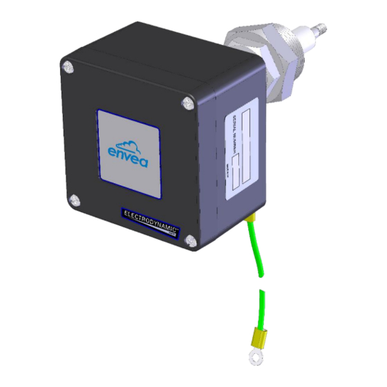
Figure 2: VIEW 370/373 X sensor (with grounding strap). Sensor The VIEW 370 (373) sensor has a metal probe rod mounted to the small ‘B’ enclosure containing the electronic circuitry. The sensor is connected to the control unit by a cable of up to 1,000m (0.6 mi) in length. For multi-sensor systems, network spurs must be used to connect the sensors to a network. -
Page 19: Principle Of Operation
The sensor utilizes the proven and reliable ElectroDynamic Probe Electrification technology patented by ENVEA, whereby the collision and interaction of particles with the probe rod (particle impingement) causes a small electrical charge transfer to occur between the particulate and the probe rod. It is this small electrical charge that provides the signal that is monitored by the electronics. -
Page 20: Unpacking And Preparation
Unpacking and Inspection Carefully unpack the units and retain the packaging to return equipment for servicing or repair. If the equipment is damaged in any way, return it to ENVEA (see the reverse of this manual) in its original packaging. -
Page 21: Grounding The Sensor
The sensor may only be fitted to a metal duct or stack. If the stack is not metallic or you are concerned that the stack may not provide a suitably earthed shield for the sensor, please contact ENVEA or your local ENVEA representative. -
Page 22: Sensor Installation
5 Sensor Installation VIEW 370/373 5 Sensor Installation Safety Information WARNING Danger from the process. It is possible that the sensors are to be installed in ducting containing process particulate that is a hazard to health. Unless the process conditions are known to be entirely safe, suitable... -
Page 23: Mounting The Sensor
VIEW 370/373 5 Sensor Installation Mounting the Sensor 5.2.1 Fitting the Sensor to the Stack 1 ............ Sensor ‘B’ enclosure 2 ............. Air purge inlet 3 ..............Lock nut 4 ..............Floating nut 5 ..............Insulator 6 ........Probe rod (insulated version) 7 ............ - Page 24 5 Sensor Installation VIEW 370/373 probe rod [6] points slightly down into the stack, allowing condensate to drain off. 3. Weld a suitable earth stud or bolt to the stack wall and connect the grounding strap (supplied with earth stud [7] and fitted on the rear of the enclosure) between sensor enclosure [1] and stack wall [9].
-
Page 25: Connecting The Sensor
Ensure the sensor is not connected to the control unit power during wiring. CAUTION The VIEW 370 (373) sensor wiring order differs from the standard ENVEA wiring connection. – Please check the wiring tables carefully. Refer to above for the location of the terminals. After the installation of IGURE the sensor, make the comms/power connections as described below. -
Page 26: Set Address Switch (Sw100)
5 Sensor Installation VIEW 370/373 Sensor Route the input cable through the cable gland nearest to connector K1. Make the connections to the K1 terminals from top to bottom as outlined below. Pins (top to bottom): Wire colour Connector name... - Page 27 VIEW 370/373 5 Sensor Installation When setting up the system, ensure that the settings in the control unit match those in the sensor (see 6.4.3 on page 24). SECTION • The default mode is ASCII: 19200 Baud, No Parity, 1 Stop bit, ASCII mode (7 bits).
-
Page 28: Basic System Setup
6 Basic System Setup VIEW 370/373 6 Basic System Setup This section provides information on the initial setup and operation of the ENVEA control unit. The same procedure applies to both the Standard Controller (Standard systems) ProController (PRO systems). advanced configuration, refer to the relevant control unit manual (see page 3). -
Page 29: Standard Controller Ui
VIEW 370/373 6 Basic System Setup Switch ON power. Red (flashing) = alarm Alarm LED [Status] Off = no alarm 6.1.2 Standard Controller UI Figure 7: Standard Controller – User interface with controls. Refer to the appropriate control unit manual to view the UI layout showing the location of the user controls and Alarm/Power indicators. -
Page 30: Main Menu Screens
6 Basic System Setup VIEW 370/373 operate them and set the function keys for quick access to frequently viewed screens. Meaning Action Symbol Displays the current top-level menu icon. ‘BACK TO TOP’ Press the BACK TO TOP button to return to the current top-level menu screen (see icon) in one click. -
Page 31: Other Symbols
VIEW 370/373 6 Basic System Setup QUALITY ASSURANCE Provides access to self-check screens, calibration, maintenance, and to run sensor checks manually. SELF-TESTS Set a password; with the Lock option PASSWORD ENTRY (to prevent unauthorized changes). Main Setup screen; access other... -
Page 32: Initial System Checks
6.4.2 Performing a Master Reset CAUTION Loss of data- Performing a Master Reset deletes all settings and logged data. Download the data to a PC using the ENVEA software tool before carrying out a system reset. 1. Open the Setup menu screen. -
Page 33: Adding Sensors To The Network
VIEW 370/373 6 Basic System Setup Adding Sensors to the Network Use the manual method of adding sensors only when manual NOTE control over the order in which the devices are displayed is required, or if only specific sensors are to be added. -
Page 34: Editing Basic Sensor Settings
6 Basic System Setup VIEW 370/373 Editing Basic Sensor Settings After running Autodetect, a configuration button for each detected channel (up to six) is displayed in the Sensor Setup section of the main Setup screen 10). IGURE Figure 10: Setup screen – Sensor/system settings. -
Page 35: Scaling Factor
VIEW 370/373 6 Basic System Setup Scaling Factor The Scaling Factor is used to scale the raw dust reading. The Scaling Factor scales the raw reading as follows: Scaled reading = Raw instrument reading x Scaling Factor The Scaling Factor is applied to the following settings: •... -
Page 36: Editing Sensor/Device Settings
6 Basic System Setup VIEW 370/373 1. Select the Setup | More Settings | Add a new device. 2. Choose the correct Channel Type from the list and set the following parameters: a. Modbus Address: set to the address set on the sensor DIP switches. -
Page 37: Editing Settings For All Sensors/Devices At Once
VIEW 370/373 6 Basic System Setup This will permanently remove all settings and logged data NOTE associated with the device. Entries in the Event Log for the device will be marked as deleted. 6.9.4 Editing Settings for all Sensors/Devices at Once... -
Page 38: Quality Assurance And Sensor Self-Tests
7 Quality Assurance and Sensor Self-Tests VIEW 370/373 7 Quality Assurance and Sensor Self-Tests Introduction The control unit QA/Self-Tests menu screen provides the following maintenance and testing functions. Function Purpose Puts sensor in a Maintenance mode to Maintenance mode allowing cleaning and maintenance of the (Start/Stop) sensor. -
Page 39: Zero And Span Checks
VIEW 370/373 7 Quality Assurance and Sensor Self-Tests The following main sensor self-tests are provided: • Zero and Span checks: used to check for faults with the sensor hardware. • Contamination check (short-circuit check): indicate the probe needs cleaning. The QA/Self-Tests menu screen displays the latest self-test results for the currently selected sensor (default: Stack1 Dust). -
Page 40: Comms Check
7 Quality Assurance and Sensor Self-Tests VIEW 370/373 Comms Check This sensor self-check tests the communication between the control unit and a selected sensor automatically and should show ‘OK’ at no loss. If this test fails, check the wiring between the control unit and the sensor. Check the address and comms settings on the sensor and control unit. -
Page 41: Maintenance
VIEW 370/373 8 Maintenance 8 Maintenance Safety Information WARNING Refer all servicing and maintenance to qualified personnel. Only suitably trained and competent staff should be carrying out the procedures in this chapter. WARNING Electric shock. The control unit contains lethal voltages! Ensure the power supply is switched off and isolated before opening the unit enclosures. -
Page 42: Placing A Sensor In Maintenance Mode
8 Maintenance VIEW 370/373 Response’ alarm will be generated in the Control Unit for that channel during the maintenance period. • Maintenance mode menu in the control unit: Sensors placed in Maintenance mode will be re-enabled automatically after 8 hours. -
Page 43: Sensor Status
VIEW 370/373 8 Maintenance Figure 15: Sensor status (list). 2. Use the scrollbar to highlight the required channel in the list, then press EDIT to put the sensor into Maintenance mode (‘MAINT’). 3. Press BACK to return to the main menu. -
Page 44: Clearing Service Messages
Action required installation Remove the sensor from the stack Inspection due 6 months for inspection and cleaning Arrange service visit by ENVEA Service due 12 months Service Engineer or a local representative Recommended return to ENVEA for Major Service due... - Page 45 VIEW 370/373 8 Maintenance 5. Check that the lock nut and floating nut move freely. 6. Apply a small amount of copper slip or grease to the mounting thread. This prevents binding and helps ensure a good grounding is maintained with the stack.
-
Page 46: Troubleshooting
8 Maintenance VIEW 370/373 Troubleshooting 8.5.1 Communication Failure The control unit can support many sensors and devices that may be spread over a wide area of plant. It is, therefore, essential to be methodical in the approach to locating the cause of communications problems. If you cannot get the complete network to communicate, it is best to disconnect some of the sensors and add them in one by one to see where the problem occurs. -
Page 47: Sensor Reading Too Low Or Too High
If the stack/duct is not metallic or you are concerned it may not provide a suitably earthed shield for the sensor, then please contact NOTE ENVEA or your local ENVEA representative (see the reverse of this manual for details). ENVEA UK Ltd... -
Page 48: Appendix A- Scaling
Appendix A– Scaling VIEW 370/373 Appendix A– Scaling Introduction VIEW 370 (373) sensors attached to a control unit can be calibrated in mg/m³ in certain applications. Calibration of each sensor is necessary on at least an annual basis NOTE and should be carried out either by ENVEA or an authorized representative. -
Page 49: Using The Calibration Tool
VIEW 370/373 Appendix A– Scaling 3. Calculate the average sensor response displayed in your control unit (‘Sensor Average’). 4. Record the sensor settings. 5. Obtain the isokinetic sampling results (‘Test Result’). 6. Calculate the new SF using the automatic or manual method (see above). -
Page 50: Calculating The Scaling Factor
Appendix A– Scaling VIEW 370/373 4. Set the Start Time by using the LEFT/RIGHT arrow keys to move between fields and pressing the + / – keys to adjust the values. The control unit will now search the logs and calculate and display the Sensor Average. -
Page 51: Appendix B- Menu Maps
VIEW 370/373 Appendix B– Menu Maps Appendix B– Menu Maps Main Menu Screens Figure 17: Menu map – Main menu screens and their icons. ENVEA UK Ltd (PC-000855-MA Issue 6, December 2021) -
Page 52: Basic Sensor Setup
Appendix B– Menu Maps VIEW 370/373 Basic Sensor Setup Figure 18: Menu map – Basic sensor setup. ENVEA UK Ltd (PC-000855-MA Issue 6, December 2021) -
Page 53: More Sensor Settings
VIEW 370/373 Appendix B– Menu Maps More Sensor Settings Figure 19: Menu map – More Settings menus. ENVEA UK Ltd (PC-000855-MA Issue 6, December 2021) -
Page 54: Basic System Setup
Appendix B– Menu Maps VIEW 370/373 Basic System Setup Figure 20: Menu map – System setup menus. ENVEA UK Ltd (PC-000855-MA Issue 6, December 2021) -
Page 55: Other Functions
VIEW 370/373 Appendix B– Menu Maps Other Functions Figure 21: Menu map – Other Functions menus. ENVEA UK Ltd (PC-000855-MA Issue 6, December 2021) -
Page 56: Quality Assurance (Qa) And Scaling
Appendix B– Menu Maps VIEW 370/373 Quality Assurance (QA) and Scaling Figure 22: Menu map – QA and Scaling menus. ENVEA UK Ltd (PC-000855-MA Issue 6, December 2021) -
Page 57: General Notices
Dispose of this product at a collection point for the recycling of electrical and electronic equipment according to local government regulations. RoHS Compliance Statement ENVEA UK Ltd is compliant with the EU Directive on the restriction of the use of certain hazardous substances in electrical and electronic equipment (RoHS Directive). -
Page 58: Index
Index VIEW 370/373 Index ROM (definition) · 3 abbreviations · 3 location requirements · 12 AIM (definition) · 3 safety alarms procedures · 1 latched alarms · 22 product · 1 AOM (definition) · 3 safety information · 14, 33 mains isolation device ·... -
Page 60: Envea Service And Support Centres
ENVEA Sales and Service engineers are available to consult regarding equipment suitability and technical support. To find a local ENVEA representative for your country or region, please contact us or visit our website www.envea.global ENVEA UK Ltd ENVEA House Rose &...
Need help?
Do you have a question about the VIEW 370 and is the answer not in the manual?
Questions and answers