
Related Manuals for envea PicoFlow


Summary of Contents for envea PicoFlow
- Page 1 OPERATING INSTRUCTIONS PicoFlow FLOW MEASUREMENT AT LOW SOLIDS/AIR RATIOS ENVEA Process GmbH - Gutedelstraße 31 – 79418 Schliengen - GERMANY Tel.: +49 (0) 7635 827248-0 / info.process@envea.global / www.envea.global...
-
Page 2: Table Of Contents
CONTENTS Page System overview ............... 3 Function . -
Page 3: System Overview
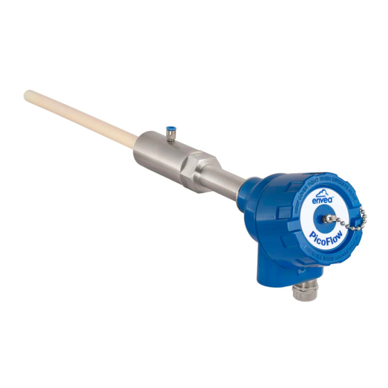
1. System overview A measuring point consists of the following components: Evaluation unit (MSE 300) in the DIN Rail housing or field housing • Weld-on sensor socket with air purge connection • Sensor • C1- or C3-Box (optional) • The system can be equipped with up to three sensors. Depended on the number of sensors, different C-Boxes (C1, C3) should be use. - Page 4 C3-Box MSE 300-FH 1 (+ 24 V) 2 (GND) Sensor 3 (A) 4 (B) Shield Sensor Sensor max. 300 m Fig. 3: Overview with C3-Box and MSE 300 in the field housing C3-Box MSE 300-DR 16 (+ 24 V) 15 (GND) 14 (A) 13 (B) max.
-
Page 5: Function
2. Function The PicoFlow is a measuring system which has been specially developed for measuring the quantity of • pneumatically conveyed solids. It is used for very small solid / air ratios. • The intrusive sensor probe is made of solid stainless steel and has an additional ceramic coating. -
Page 6: Safety
3. Safety The PicoFlow was designed, built and tested for safety and is shipped in this condition. Components within the supplied system could be hazardous if not unpacked, installed, connected and commissioned by authorised qualified persons. All operating instructions must be read, and understood, before handling the system. Failure to do so will cause the warranty to be revoked. -
Page 7: Mounting And Installation
Mounting and installation 4.1 Delivery range: Evaluation unit (MSE 300) in the DIN Rail housing or field housing • Weld-on sensor socket with air purge connection • Sensor • Operating instructions • C1- or C3-Box (optional) • 4.2 Auxiliary Drill Ø 27 mm for steel •... - Page 8 Weld the sensor accommodation to the duct. The plastic inlay • and the air connection must be removed before welding. Drill the hole of 27 mm diameter through sensor accommodation. • Ensure that the borehole is not angled so that the sensor can be installed precisely at a later stage.
-
Page 9: Mounting The Evaluation Unit
4.4 Mounting the Evaluation unit The evaluation unit can be installed at a maximum distance of 300 m from the sensor. A cable of type “Ölflex Classic 110 CY” is recommended. The cable should be four wired, twisted and shielded. A minimum cable cross-section of 0.75 mm²... - Page 10 Fig. 9: Dimension of the MSE 300-FH (side view) 175 mm 35 mm 35 mm 35 mm 163 mm max. max. max. max. 13 mm 13 mm 13 mm 13 mm Fig. 10: Dimension of the C3-Box...
- Page 11 113 mm 125 mm 50 mm max. max. 13 mm 13 mm Fig. 11: Dimension of the C1-Box Fig. 12: Dimension of the PicoFlow sensor...
-
Page 12: Use In Hazardous Areas
4.5 Use in Ex hazardous areas Marking DustEx: II 1/2D Ex ia/tb IIIC Tx* °C Da/Db *-electronics / enclosure Zone 20: -20 °C _ < T _ < 250 °C process Zone 21: -20 °C _ < T _ < 60 °C - Equipment group: 2 - Equipment category: 1/2 Electrode zone 20 / enclosure zone 21... -
Page 13: Electrical Connection
Electrical connection 5.1 Terrminal layout MSE 300-DR Current output Current output Input Input - 4 ... 20 mA + 4 ... 20 mA Power supply Power supply 0 V DC + 24 V DC Not used Alarm relay Alarm relay Alarm relay NC (break contact) NO (make contact) -
Page 14: Terminal Layout Mse 300-Fh
5.2 Terminal layout MSE 300-FH Fig. 15: Electrical connection of the MSE 300-FH Evaluation unit Terminal No. Connection Power supply connection L / +24 V Input power supply 230 V / 50 Hz, 110 V / 60 Hz (optional 24 V DC) N / 0 V Input power supply 230 V / 50 Hz, 110 V / 60 Hz (optional 24 V DC) Earth... -
Page 15: Terminal Layout C-Boxes
5.3 Terminal layout C-Boxes Evaluation unit Sensor 1 Sensor 2 Sensor 3 Fig. 16: Electrical connection for the C3-Box Sensor 1 / 2 / 3 Power supply + 24 V 2 Power supply 0 V 3 RS 485, Data A 4 RS 485, Data B S Shield Sensor 1... -
Page 16: Operator Interface
• Field housing with display, alternative operation via PC software • One to three sensor system In the following, the basic operation of the PicoFlow system will be described as a one sensor system without re-entering the differences between the various variants. -
Page 17: Display
If no selection is made, the initialization disappears and the German language with a PicoFlow sensor is selected. Initialization screen when the Evaluation unit in the field housing started first time. - Page 18 With the key [I] you can choose between different Sensor Status information windows. The first window shows the raw values, Temp Raw value Stat temperature and the status of the sensor. 0.000123 The second window displays the error memory. 0.000213 Recent error codes always come first.
-
Page 19: Pc Interface
• Baud rate 9600, 8, E,1 • An RS 485 to USB adapter can be purchased from ENVEA Process. ✔ For the USB connection to the DIN Rail version is a standard USB-A-B cable included. The USB connection is a point-to-point connection that is not BUS-capable. The ModBus address and the baud... - Page 20 The edited data is transmitted to the evaluation unit via “Device program”. Critical data concerning the ModBus communication and the calibration must be confirmed before the parameters are transmitted to the evaluation unit: ✔ If, when saving the the parameters in the evaluation unit, the system calibration data is changed, this action must be confirmed by checking “Overwrite calibration”.
-
Page 21: One Or More Sensor Systems
6.4 One or more sensor systems Up to three sensors can be connected to a evaluation unit if, for example, a larger flow section needs to be illuminated. In the evaluation unit, the corresponding number of sensors will then be registered and a joint average value will be calculated from their measurements. - Page 22 With delivery of a multi-sensor system the sensors will be preconfigured on the addresses 1 – 2 – 3 and • noted in the evaluation unit as active. Sensors and evaluation units, which are not preconfigured for a multi-sensor system always have •...
-
Page 23: Menu Structure
6.5 Menu structure The menu structure supports the user when adjusting the measuring range, the calibration, the measurement values and the choice of additional functions. In this connection, the numbering both on the display and in the PC interface is identical: 1. - Page 24 Calibration Deposit a calibration curve Depending on the selection under 8.2.4 Calibration, the parameters to be entered are changing. Average-Calibration From the average value of all sensors, a common calibration table is created for throughput calculation. Input: 0.01 … 9.99 Calibration factor Factor for the subsequent adjustment of the actual measurement.
- Page 25 Single calibration Each sensor is assigned an individual calibration table. Afterwards, a throughput calculation takes place on the basis of the individual throughput values. Input: 0.01 … 9.99 Calibration factor Factor for the subsequent adjustment of the actual measurement. All measurements are scaled by this factor.
- Page 26 Calibration Calibration sub-menu for sensor 2 2.5.1 Calibration factor Input: 0.01 … 9.99 Factor for the subsequent adjustment of the actual measurement of sensor 2. 2.5.2 P1 value Input: measurement Output measurement in the selected mass/time unit. 2.5.3 P1 calibration Transfer: raw value Transfer of the current raw value (filtered) from the mass flow with the key [ ←...
- Page 27 Alarm Settings for relay contacts Alarm type Selection: Min / Max / none The relay is operated if the measurement exceeds or falls below the max. limit or min. limit. Alarm value Input: 0 … 999.9 Limit value for monitoring min. or max. Input: 0.1 …...
- Page 28 Analog output Settings and calibration of analogue output Input: 0 … 22 mA Lower limit Standard: 3.2 mA Input: 0 … 22 mA Upper limit Standard: 21 mA Input: 0 … 22 mA Alarm value Standard: 2 mA Selection: Alarm: Alarm value at output, during alarm Alarm mode alarm / freeze measuring value is 0.
- Page 29 / or the 4.1 Lower limit must be set to 4 mA. The PicoFlow gives only to analog output 1 a signal for the flow rate. If the settings of the 4 mA or 20 mA signal are changed, the checkbox Overwrite calibration must be set.
- Page 30 Pulse output Passive signal for pulse cleaning or output of a totaliser Function Selection: none / None: No pulse output cleaning / quantity Cleaning: Possibility to control a solenoid valve for compressed air-fluid. 5.4 Pulses/unit without function. Quantity: The quantity is send as an impulse sequence to the output;...
- Page 31 Analogue input Possibility of autocorrection via external current signal. The connection of the current input is not galvanically isolated. If the connection is incorrect, the CPU of the evaluation unit can be destroyed. An external galvanic isolation, by current disconnector or similar shall be provided. Input calibration 4 mA Selection: calibrate 4 mA input...
- Page 32 Digital input Selection of function for external control. Digital input 1 Submenu 7.1.1 Function Selection: None: digital imput disabled Reset totaliser: totaliser would be none / reset totaliser / AutoCal reset to zero AutoCal: an auto calibration will be start Selection: NO / NC 7.1.2 Working direction...
- Page 33 (This function should only be used by trained personnel of ENVEA Process.) Average: Calibration by the average value from raw values: The throughput will be calculated with a common calibration table after forming the average from raw values.
- Page 34 The evaluation unit verifies the availability of SolidFlow 2.0 / Paddy / registered sensors on the selected type, PicoFlow / MaxxFlow HTC / calculates the measurement values on this DensFlow / SpeedFlow 2.0 / basis and signals if necessary corresponding SlideControl 2.0 / ProSens / errors.
- Page 35 PC software. Only according to instructions from personnel of ENVEA Process: If a detailed error analysis is necessary, a copy of all ModBus registers can be stored as a text file in the installation folder of the software by clicking on the sensor dump.
-
Page 36: Start-Up Procedure
Start-up procedure Basic start-up Upon delivery, the sensor is not calibrated to the product to be measured and must be parameterised when started up. During the process, the mass flows measured by the sensor will be assigned to the display values and output quantities required by the user. -
Page 37: Adjusting The Measurement Values
For an evaluation of the recorded log file, it must be opened with Excel or a similar program. The content of each column of the log file is named in the first line. In order to determine the appropriate raw value for a calibration point, the mean value must be determined from the period of the reference extraction. -
Page 38: Error Signalling
8. Error signalling For monitoring the availability a wide range of functions for self-diagnostics were integrated, in order to signal various errors: 1. Fatal error (ERR): Fatal errors (ERR) always set the current output to the set alarm value. Technical problems or problems with the complete system are displayed on the touchscreen. -
Page 39: Compatibility
8.1 Compatibility For the PicoFlow system two different software versions for the evaluation unit and associated PC software are available. Technical innovations have caused a supplement of new functions, so that only the corresponding versions can be used together on evaluation unit and PC:... -
Page 40: Connection Examples
9. Connection examples 9.1 Digital input ▼ = ((U - 1,6 V) / 20 mA) - 2 kW 9.2 Impulse output Open Collector Open: 0 V Closed: Ub - 0.7 V Closed: Ub - 0.7 V Open: Ub Closed: 0.7 V Closed: 0.7 V Open Collector R = (Ub - 0,7 V)/l... -
Page 41: Maintenance
In case of a defect during the warranty period, defective components are repaired or are replaced free of charge. Replaced parts turn into the property of ENVEA Process. If desired by the costumer that the parts should be repaired or replaced in its factory, then the costumer has to take over the costs for the ENVEA Process-service staff. -
Page 42: Error Codes
If not helpfully sensor exchange. E100 2 mA Parameter table not read- Turn power off / on. able. If not helpfully sensor exchange. A detailed error description and following troubleshooting can be carried out by trained ENVEA Process technicians. -
Page 43: Technical Data
Data backup Flash memory Pulse output Open Collector - Max. 30 V, 20 mA ENVEA Process GmbH Gutedelstraße 31 · 79418 Schliengen (Germany) Fon +49 7635 827248-0 · Fax +49 7635 827248-48 · www.envea.global PART OF THE ENVEA GROUP DE 05/08/2020...
Need help?
Do you have a question about the PicoFlow and is the answer not in the manual?
Questions and answers