
Related Manuals for envea AirFlow P


Summary of Contents for envea AirFlow P
- Page 1 OPERATING INSTRUCTIONS AirFlow P VOLUME CURRENT MEASUREMENT ENVEA Process GmbH - Gutedelstraße 31 – 79418 Schliengen - GERMANY Tel.: +49 (0) 7635 827248-0 / info.process@envea.global / www.envea.global...
- Page 2 If you want to communicate with our sensor using our dedicated software, you need to download the latest version on our website and install it. https://www.envea.global/solutions/process-optimization/dahs-software/ It might also be necessary to install drivers, also available on our website.
- Page 3 1st start note 3. MSE 300-DR / -DR2 (NO SCREEN) Our dedicated software must be used to connect to the sensor evaluation unit. Select software language Right click on „Sprache/Language/ Langue“ and select desired language. Connect to sensor Select the correct COM port and connect to the device using the „read device“...
-
Page 4: Table Of Contents
CONTENTS Page System overview ..........5 2. -
Page 5: System Overview
System overview A measuring point consists of the components: Evaluation unit in the DIN Rail housing or field housing • Double weld-on socket for sensor mounting • Sensor (consisting of 2 x antenna, 1 x electronic box) • Assembly instructions •... - Page 6 The system can be equipped with up to three sensors. Accordingly, different C-Boxes (C1, C3) are used. C3 box MSE 300-FH 1 (+ 24 V) 2 (GND) Sensor 3 (A) 4 (B) Shield Sensor Sensor max. 300 m Fig. 3: Overview with C3-Box and MSE 300-FH C3 box MSE 300-DR / -DR2 1 (+ 24 V)
-
Page 7: Function
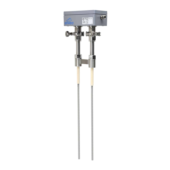
2. Function The AirFlow P is a volumetric flow meter specially designed for dusty applications. The sensor technology is based on the electrodynamic measuring principle. Every particle that flies past the antenna within a radius of 300 mm generates an electrical signal. The signals from the two antennas are further processed in the sensor‘s electronics box. -
Page 8: Safety
The measuring system may only be installed in metallic pipes to measure the medium passing • through them. It is not suitable for any other use or measuring system modifications. Only genuine spare parts and accessories from ENVEA Process may be used. • 3.2 Identification of hazards Possible dangers when using the measuring system are highlighted in the operating instructions with •... - Page 9 If the device is operated under high pressured conditions, there is a risk of explosion. When cleaning • or blowing out the pipe and when transporting material, always ensure that the permissible pressure according to the DGRL is not exceeded. Due to the process, hot components on the device can cause burns.
-
Page 10: Maintenance
3.5 Technical statement The manufacturer reserves the right to change any technical data concerning technical developments, without prior notice. If any queries arise, ENVEA Process GmbH will be happy to inform customers of any possible changes made. 3.6 Reliability For any additional information concerning product reliability, please contact ENVEA Process GmbH. -
Page 11: Mounting And Installation
Suitable tools for the electrical connection • 4.3 Determining the installation position To determine the correct position of the AirFlow P, proceed as follows: The sensor can be used in round or angular pipes. In the case of horizontal or sloping •... -
Page 12: Installation In Non-Metallic Lines
In applications where the mounting location requirements cannot be fully met, the best possible mounting position should be selected. The AirFlow P should be installed so that the two antennas of the sensor are aligned with the material flow. 2. In horizontal pipes with a round cross-section, the AirFlow P can be installed in any position above the horizontal axis (between 9 and 3 o‘clock). -
Page 13: Installation Of The Sensor
4.5 Installation of the sensor At the selected installation position, the double weld-on sleeve must be installed on the line wall and drilled out completely to the inner diameter of the sleeve. The sleeve must be installed with the material flow direction. Attention! After drilling, it is essential to check whether any burr has formed on the drill edges as a result •... -
Page 14: Dimensions
4.6 Dimensions Fig. 7: Dimensions of the MSE 300-DR Fig. 8: Dimensions of the MSE 300-DR2... - Page 15 Fig. 9: Dimensions of the MSE 300-FH 113 mm 125 mm 50 mm max. max. 13 mm 13 mm Fig. 10: Dimensions C1 box 163 mm 175 mm 35 mm 35 mm 35 mm max. max. max. max. 13 mm 13 mm 13 mm 13 mm...
- Page 16 G 1" 226 mm 43 mm 80 mm 100 mm Fig. 12: Dimensions G 1“ double socket Abb. 13: Dimensions G 1"-double-screw on-socket for thin channels 120,0 220,00 100,0 Fig. 14: Dimensions AirFlow P sensor...
-
Page 17: Electrical Connection
Electrical connection Different variants of the Evaluation unit are available for the evaluation of the sensor signals. The MSE 300-FH variants are supplied in an IP65 housing and can be installed in a free environment according to the specification. The MSE 300-DR variants are designed for installation in an electrical cabinet. The MSE 300-DR2 is a variant of the MSE 300-DR and can be extended to a display as required. -
Page 18: Terminal Layout Mse 300-Dr2
Terminal layout MSE 300-DR2 Alarm relay Alarm relay Alarm relay Not used NO (make contact) NC (break contact) 1. Digital pulse 1. Digital pulse 2. Digital pulse 2. Digital pulse output (+) output (-) output (+) output (-) 1. Current output 1. -
Page 19: Terminal Layout Mse 300-Fh
5.3 Terminal layout MSE 300-FH Fig. 17: Electrical connection of the MSE 300-FH Evaluation unit Terminal No. Connection Power supply connection L / +24 V Input power supply 230 V / 50 Hz, 110 V / 60 Hz (optional 24 V DC) N / 0 V Input power supply 230 V / 50 Hz, 110 V / 60 Hz (optional 24 V DC) Earth... -
Page 20: Terminal Layout Of C-Boxes
5.4 Terminal layout of C-Boxes It is not needed to install a C1-Box, the system also run without C1-Box. The C1-Box could be installed in-between sensor and Evaluation unit. The C1-Box could be used to secure the sensor and Evaluation unit in case of electric error. The C3 box is absolutely necessary as soon as an averaging of up to three sensors at one measuring point is to take place. -
Page 21: Electrical Connection Sensor
5.4 Electrical connection sensor PIN 1: Power supply + PIN 2: Power supply – PIN 3: Modbus A PIN 4: Modbus B PIN 5: Shield Fig. 20: Electrical connection of the plug connector... -
Page 22: Operator Interface
6. Operator interface The Evaluation unit is a multi-sensor Evaluation unit. So it is strongly recommended to check before commissioning whether the correct sensor is selected under menu item System. The operator interface differs depending on the system design: • DIN Rail housing without touchscreen, operation via PC software •... -
Page 23: Configuration Via Display
To be available: SolidFlow 2.0, Paddy, PicoFlow, MaxxFlow HTC, AirFlow P DensFlow, AirFlow P, SpeedFlow 2.0, SlideControl 2.0, ProSens, M-Sens 2, M-Sens 3, M-Sens WR, M-Sens WR2. Afterwards the start page appears. The start page in the display shows the following values: AirFlow P Name „AirFlow P“, a freely selectable text... - Page 24 The [ I ] key can be used to call up an information window. Sensor status The first window displays the raw values, temperature and the status of the sensor. Temp raw value Stat 63.0 0.000123 The error memory is displayed in the second window. The most recent error codes are always listed first.
-
Page 25: Configuration Via Pc-Software
• Parity: even • An RS 485 to USB adapter can be purchased from ENVEA Process. ✔ A standard USB-A-B cable is supplied for the USB connection to the DIN Rail version. The USB connection is a point-to-point connection that is BUS-enabled. The ModBus... - Page 26 Communication is established by clicking on “Read device”. The acknowledgement message “Parameter read in” is displayed. If an error message is displayed instead, check the communication parameters and cable connections between the PC and the Evaluation unit. The edited data is transmitted to the Evaluation unit via “Program device”. Critical data concerning the ModBus communication and the calibration must be confirmed before the parameters are transmitted to the Evaluation unit: ✔...
-
Page 27: One Or More Sensor Systems
7.4 One or more sensor systems Up to three sensors can be connected to an Evaluation unit if, for example, a larger flow section needs to be monitored. In the Evaluation unit, the corresponding number of sensors will then be registered and a joint average value will be calculated from their measurements. - Page 28 With delivery of a multi-sensor system the sensors will be preconfigured on the addresses 1 – 2 – 3 • and noted in the Evaluation unit as active. Sensors and Evaluation units, which are not preconfigured for a multi-sensor system always have •...
-
Page 29: Menu Structure
6.5 Menu structure The menu structure supports the user when adjusting the measuring range, the calibration, the measurement values and the choice of additional functions. In this connection, the numbering both on the display and in the PC interface is identical: Measurement range Setting all relevant measuring range settings 1.1 Tag No. - Page 30 Calibration Deposit a calibration curve Depending on the selection under 7.2.7 Calibration, the parameters to be entered are changing. . Average-Calibration From the average value of all sensors, a common calibration table is created for volumeflow calculation. Calibration factor Input: 0.01 … 9.99 Value for adjusting the measured speed.
- Page 31 Single calibration Each sensor is assigned an individual calibration table. Afterwards, a throughput calculation takes place on the basis of the individual throughput values. Calibration factor Input: 0.01 … 9.99 Factor for the subsequent adjustment of the actual measurement. All measurements are scaled by this factor.
- Page 32 Calibration sensor 1 Calibration sub-menu for sensor 1 2.6.1 Calibration factor Input: 0.01 … 9.99 Factor for the subsequent adjustment of the actual measurement of sensor 1. 2.6.2 P1 value Input: measurement Output measurement in the selected mass/time unit. Transfer: raw value 2.6.3 P1 calibration Transfer of the current raw value (filtered)
- Page 33 Alarm Settings for the alarm via the relay contacts Alarm type Selection: The relay is activated when the measured Min / Max / None value exceeds the Max. limit or undershoots the Min. limit. Alarm value Input: 0 … 999.9 Limit value for monitoring Min.
- Page 34 Analogue output Setting and calibrating the analogue output Lower limit Input: 0 … 22 mA Standard setting: 4 mA Upper limit Input: 0 … 22 mA Standard setting: 20 mA Alarm value Input: 0 … 22 mA Value to be output at pending alarm (Standard setting 2 mA) Alarm mode Selection:...
- Page 35 Analog output 3 Submenu 4.7.1 Calibration 4 mA Selection: Key functions can be used to set the Setting the output current current and equalise it to the receiver side. Selection: 4.7.2 Calibration 20 mA Key functions can be used to set the Setting the output current current and equalise it to the receiver side.
- Page 36 Pulse output Passive signal for pulse cleaning. Function Selection: OFF / Cleaning OFF: No pulse output Cleaning: Option for actuation of a solenoid value for pneumatic air flushing. Input: 1 s … 600 s Pulse period Duration between two pulses Input: 1 s …...
- Page 37 Current input Option for auto-correction by external current signal. The signal is not electrically isolated. If the connection is incorrect, the CPU of the Evaluation unit may be destroyed. An external, galvanic isolation by means of a current disconnector or similar must be provided.
- Page 38 (This function should only be used by trained ENVEA Process personnel). Average: The mean value from all activated sensors is stored in a common calibration table in a common calibration table for the calculation of the measured value.
- Page 39 SlideControl 2.0 / ProSens / possible errors are displayed. Incorrect M-Sens 2 / M-Sens 3 / sensor selection leads to communication M-Sens WR2 / AirFlow P denial. Display Submenu Selection: ON /OFF ON: The key for querying sensor 7.3.1...
- Page 40 In the case of a change of display, the PC software can be used to adjust the contrast, if necessary. Only by instruction of trained personnel from ENVEA Process: If a detailed error analysis is necessary, you can use the PC software by clicking on Sensor Dump to save a copy of all ModBus registers as a text file in the installation folder of the software.
-
Page 41: Start-Up Procedure
Start-up procedure Basic start-up procedure The sensor is an absolute measuring device and must be parametrised during the commissioning procedure. The following points must be checked before parametrisation: The correct installation of the sensor in the conveyor line. • The correct connection between the sensor and the Evaluation unit. •... -
Page 42: Adjusting The Measurement Values
Adjusting the measurement values The system's additional functions can be set in the following menus: Alarms Throughput upper/lower limit values can be set in 3. Alarm. A sensor monitoring alarm can also be activated here. Analogue output The analogue output values are assigned in 4. Analogue output. Upper and lower limits of the permitted power and fault current are set here. -
Page 43: Error Signalling
Error signalling To monitor availability, comprehensive system diagnostic functions have been integrated to signal various errors: 1. Serious errors (ERR): Serious errors (ERR) always set the current output to the configured alarm value. Technical problems affecting the sensor or the entire system that require replacement or repair of a component are displayed: •... -
Page 44: Maintenance
ENVEA Process plant free of charge at the discretion of ENVEA Process. Replaced parts will become the property of ENVEA Process. If the customer requests that parts be repaired or replaced at its plant, the customer must pay the travel expenses for ENVEA Process service personnel. -
Page 45: Error Codes
Set parameters, configuration flags, set fixed speed, check process PROC P2000 4…20 mA Empty calculation buffer Wait, reset if necessary if not gone after some time A detailed error description and subsequent troubleshooting can be carried out by trained ENVEA Process GmbH personnel. -
Page 46: Technical Data
12. Technical data Sensor Power supply 24 V DC, fed by Evaluation unit Measuring range from 1 mg/m Speed range 1 m/s … 100 m/s Process temperature -20 … +250 °C Ambient temperature -20 … +60 °C Housing material Aluminium Sensor rod material Stainless steel Protection type... - Page 47 Flash memory Pulse output 2 x Open Collector - max. 30 V, 20 mA ENVEA Process GmbH Gutedelstraße 31 · 79418 Schliengen (Germany) Fon +49 7635 827248-0 · Fax +49 7635 827248-48 · www.envea.global PART OF THE ENVEA GROUP EN 11/04/2022...
Need help?
Do you have a question about the AirFlow P and is the answer not in the manual?
Questions and answers