Table of Contents
Advertisement
Quick Links
Advertisement
Table of Contents

Related Manuals for envea STACK 710


Summary of Contents for envea STACK 710
- Page 1 STACK 710 USER MANUAL...
- Page 3 STACK 710 Particulate Measurement System USER MANUAL Publication Part Number: PC-000878-MA...
- Page 4 ENVEA UK Ltd. Disclaimer ENVEA reserves the right to revise and update this documentation from time to time without obligation to provide notification of such revision or change. Revised documentation may be obtainable from ENVEA.
-
Page 5: Table Of Contents
Important information for installing the Transceiver and Retro-reflector ....... 19 Mounting the Transceiver and Retro-reflector ............20 Electrical Connections ................. 21 Transceiver Connections ................22 3.10 Connection to ENVEA Control Unit ..............23 3.11 Cable Specification ..................25 3.12 PC Software (PC-ME DUST TOOLS) ............... 26 3.13... -
Page 6: List Of Figures
Configuration Record Sheet................61 ENVEA SERVICE AND SUPPORT CENTRES ___________________________ 68 List of Figures Figure 1: STACK 710- general overview..............13 Figure 2: STACK 710- installation diagram..............14 Figure 3: STACK 710- installation schematic ............... 16 Figure 4: STACK 710- pathlength distance..............17 Figure 5 Mounting flange schematic. - Page 7 Figure 19: Examples of Different Pathlength Correction Factors (PLCF)....... 52 Figure 20: STACK 710- overview................53 Figure 21: STACK 710- Transceiver................54 Figure 22: STACK 710- removing the cover..............60 ENVEA UK Ltd (PC-000878-MA Issue 7, December 2021)
- Page 8 STACK 710 [This page is left blank intentionally.] viii ENVEA UK Ltd (PC-000878-MA Issue 7, December 2021)
-
Page 9: Introduction
Equipment Operation Use of this instrument in a manner not specified by ENVEA may be hazardous. Electrical Power Supply Before working on the electrical connections, all electrical power lines to the equipment must be isolated. - Page 10 1 Introduction STACK 710 Lifting Instructions Where items are too heavy to be lifted manually, use suitably rated lifting equipment. Refer to the Technical Specification for weights. All lifting should be done as stated in local regulations. ENVEA UK Ltd...
-
Page 11: Limits Of Use
STACK 710 1 Introduction Limits of Use To achieve optimum performance and safe operation, the equipment must be operated within the limits detailed in the section of this System Specification manual. Operation outside these limits may result in damage to the equipment or failure to achieve the performance specification. -
Page 12: Certification
Certification 1.4.1 Conformance and Related standards ENVEA UK Ltd hereby declares that this instrument – within the limits specified in this manual – conforms to the essential requirements and other provisions of the pursuant of the following: 1. European Union Directives: Low Voltage and EMC. -
Page 13: Product Description
2.1.1 Power Supply The STACK 710 operates from a 24 V DC supply. 2.1.2 Analogue Output The STACK 710 Dust (opacity monitor) has a current loop output that may be set to one of the four functions: • • Opacity Dust •... -
Page 14: Installation Diagram
CALIBRATION c. ALARMS 2.1.4 Computer Interface Operation The STACK 710 Dust (opacity monitor) may be connected to a computer or data acquisition system via its RS485 Modbus interface. Installation Diagram The STACK 710 Dust Opacity Monitoring System, showing all components installed. -
Page 15: Installation Instructions
STACK 710 3 Installation Instructions Installation Instructions Installation Checklist 1. Select the installation location. 2. Install the mounting flanges. 3. Install the Air Blower Unit(s) for the purge air supply. Consult the Air Blower Unit Instruction Manual for full details. -
Page 16: Maintaining The Pathlength During Installation
Figure 3: STACK 710- installation schematic Maintaining the pathlength during installation The installation pathlength is defined as the distance between the outer faces of the mounting flanges fitted to the stack or duct. -
Page 17: Installing The Mounting Flanges
Figure 4: STACK 710- pathlength distance. Installing the Mounting Flanges The STACK 710 is supplied with two mounting flanges with stand-offs (sleeves) used to mount the Transmissometer onto the stack or duct. 1. Each sleeve is 128 mm (5.04”) long.Adjust the sleeves to obtain the proper measurement path. -
Page 18: Mounting Details
Standpipe. Figure 6: Front view of Air Purge showing mounting holes. Flange Alignment Tool Please refer to the STACK 710 Datasheet and Order Codes Guide available from ENVEA, your ENVEA representative, or the ENVEA website (www.envea.global). ENVEA UK Ltd... -
Page 19: Important Information For Installing The Transceiver And Retro-Reflector
STACK 710 3 Installation Instructions Important information for installing the Transceiver and Retro-reflector Figure 7: Installing the Transceiver and Retro-reflector (side view). Figure 8: Installing the Transceiver and Retro-reflector (top view). 1. Check the dimensions carefully before installation. 1a. Allow at least 1 m (3.3 ft) for mounting and removal procedures 1b. -
Page 20: Mounting The Transceiver And Retro-Reflector
3 Installation Instructions STACK 710 3. The flange-to-flange path length (5) is factory set and must not be changed. It is given on the back of the Transceiver. 4. Pre-terminated 5 m power and data cables are supplied with this instrument. -
Page 21: Electrical Connections
STACK 710 3 Installation Instructions Electrical Connections All switch cabinets, distribution boxes, fuses and other components for electrical installation must be provided by the customer, as must the mains power supply connections. Installation should be carried out by a competent person, and cables should satisfy current carrying capacity and voltage rating. -
Page 22: 3.10 Transceiver Connections
3 Installation Instructions STACK 710 3.10 Transceiver Connections Figure 10: Transceiver connections. ENVEA UK Ltd (PC-000878-MA Issue 7, December 2021) -
Page 23: 3.11 Connection To Envea Control Unit
3.11 Connection to ENVEA Control Unit A spur unit is supplied to facilitate connecting the power and comms cable to the ENVEA control unit. Standard ENVEA 4-core cable should be used to connect from the Control Unit to the terminal box. - Page 24 3 Installation Instructions STACK 710 Middle Connector (from left to right): to sensor connector A (power): Blue Screen Screen Right Connector (from left to right): to sensor connector C (comms): Black Comms B (RS485 D0) Yellow Comms A (RS485 D1)
-
Page 25: 3.12 Cable Specification
STACK 710 3 Installation Instructions 3.12 Cable Specification Cable types recommended: Electrical Nº of Core Size Core Size Core Size Screened Supplied Connections Cores strands/dia Overview 16/0.2 ENVEA 0.25 7/0.2 ENVEA 0.25 7/0.2 ENVEA 16/0.2 0.5 to 1.5 22 to 16 Customer to 30/0.2... -
Page 26: Pc Software (Pc-Me Dust Tools)
Ethernet (RJ45; via Modbus TCP) USB 2.0 cable, standard type A-to-A, M:M Optical disc drive PC-ME DUST TOOLS software is supplied on a software CD and is also available for download from the ENVEA UK (DVD/CD) website ( www.envea.global/s/process-en/dahs- software/pc-me-dust-tools/... -
Page 27: Getting Started
4 Getting Started Getting Started User Interface The STACK 710 is operated from the User Interface in the Transceiver. The User Interface has four function keys and four illuminated indicators. The liquid crystal display normally indicates the opacity measured by the instrument. -
Page 28: Function Keys
When the value is correct, press to store it permanently. To abandon the change and revert to the previous value, press The STACK 710 provides an accelerator facility for entering large numbers. To increase the value, hold down the arrow. Initially, the least significant digit is highlighted white on black. -
Page 29: Stack 710 Symbols
STACK 710 4 Getting Started STACK 710 Symbols Enter Show Negative Values Exit Alarm Output Type Down Output Range Unlock Constant Current Supervisor Unlocked Dust Settings Engineer Unlocked Parameter Number Lock Scroll Parameters Locked List Faults Calibration Clear Faults Settings... -
Page 30: Glossary Of Terms
4 Getting Started STACK 710 No Negative Values X Constant Show Negative Values B Constant Opacity Opacity Density Dust Density Previous Calibration Glossary of Terms Opacity Optical Density Dust Dust Density Averaging Time period used to calculate block Status System... -
Page 31: Using The Instrument For The First Time
4.5.2 Check the Pathlength Correction Factor If the STACK 710 is to be used to report Opacity, the Pathlength Correction Factor (PLCF) must be set correctly. PLCF is not relevant for Dust Density or Optical Density (Extinction) measurements. -
Page 32: Align The Retro-Reflector
4 Getting Started STACK 710 Align the Retro-reflector Captive Socket Head Screws Quick Release Clip Figure 14: Opening the Retro-reflector case & releasing the reflector. 1. Open the Retro-reflector case by undoing the two quick-release clamps. 2. Release the Retro-reflector Mount by unscrewing the two captive socket head screws on either side of the Retro-reflector Mount. -
Page 33: Align The Transceiver
STACK 710 4 Getting Started Figure 15: Aligning the Retro-reflector. Align the Transceiver Transceiver Alignment Target 1. Observe the alignment target through the window (3). A bright green spot (4) should be visible. 2. To move the green spot horizontally, adjust M10 nut (1) on the air purge... -
Page 34: Setup Calibration Check Interval
Switch off the power. Remove the rear cover from the Transceiver (see section C -4) and locate Link 1 and Link 2 on the Main printed circuit board. The STACK 710 is shipped set for Active output with the Links in the following positions:... - Page 35 STACK 710 4 Getting Started Use the arrows to select Output Type and press Use the arrows to select Opacity , Optical Density Dust Density Press to return to Output Range. Use the arrows to select Output Range and press...
-
Page 36: 4.10 Setup Alarm
The STACK 710 is now ready for use. 4.12 Modbus Interface Modbus communications, based on the RS485 duplex hardware standard, provide direct access to the STACK 710 system data. Details of the Modbus protocol are available from the Modbus website . The STACK 710 implements www.modbus.org... - Page 37 STACK 710 4 Getting Started - Termination resistor Supplied ON The STACK 710 is shipped with the following default communication settings: Baud rate: 57 00 Parity: Even Data bits: Stop bits: Slave Address: The Baud rate, Parity and Slave Address can be changed as follows:...
-
Page 38: 4.13 Modbus Registers
4 Getting Started STACK 710 4.13 Modbus Registers A brief list of the most useful Registers is in section . A complete list is included on the CD-ROM. Note: The definition of Register Numbers given in the Modbus standard can confuse. For historical reasons, Registers are given decimal numbers beginning at 1, but Register 1 is located at Address Offset 0. - Page 39 STACK 710 4 Getting Started Indicates the Number of 0 - 32 number of faults faults currently present (regardless of mask states) Error Flags Error flags Bit 0 = Zero motor jammed Bit 1 = Upscale motor jammed Bit 2 = Source LED fail...
-
Page 40: Periodic Mode Of Operation
The opacity value of the span filter (9) is shown on the calibration certificate which accompanies the instrument. As required by ASTM D 21 -07, the STACK 710 indicates the PLCF value on the current loop output for 90 s at the end of each calibration check. The value is scaled from 0.0 to 10.0. -
Page 41: Calibration Audit
Displayed Opacity = 1 - (1-FilterOpacity) 1/PLCF The operating wavelength of the STACK 710 is 525 nm. All audit filters will be calibrated at this wavelength. Remove the filter, insert the next filter and record the reading. -
Page 42: Clear Stack Calibration
Alternatively, the instrument may be removed and attached to test stands or a pipe for calibration. The STACK 710 provides a convenient facility for testing on a workbench or other flat surfaces. The Transceiver may be laid on its left side and the Retro-reflector on its right side;... -
Page 43: Gravimetric Calibration (Isokinetic Calibration)
When the hourglass disappears, the Clear Stack Calibration is complete. Gravimetric Calibration (Isokinetic Calibration) The STACK 710 measures the opacity of dust and smoke emissions. As explained in the Reference section of the manual, this may be converted to Dust Density using calibration constants. - Page 44 If the data points form a marked curve rather than a straight line, change the Trendline to a Polynomial of order 2. The coefficient of the x2 term is the Dust Gain 2 calibration constant. To enter the Dust Gain and Offset values into the STACK 710, press Unlock displayed, press Use the...
-
Page 45: Setting Calibration Constants Manually
Press three times to return to the main display. Setting Calibration Constants Manually If the STACK 710 is miscalibrated, it is possible to recover the situation by replacing the erroneous calibration constants. The Previous constants and the constants determined during Factory testing are stored in the instrument. - Page 46 5 Periodic Mode of Operation STACK 710 Use the arrows to select Previous Calibration and press Use the arrows to select Use Previous Calibration and press Confirm is displayed. Press The Previous Calibration constants are copied into the Current Calibration constants.
- Page 47 In the event of a major malfunction resulting in loss of the calibration data, the STACK 710 provides a facility for entering the calibration constants manually. The original calibration data determined during factory testing are recorded on the Calibration Report.
-
Page 48: Theory Of Operation And Application
The wavelength response of an opacity monitor must mimic that of the human eye. An instrument must have a nearly photopic response. The STACK 710 uses a high-intensity green LED light source to achieve this. Beer-Lambert’s Law... - Page 49 STACK 710 6 Theory of Operation and Application Since opacity (Op) = 1 – τ, the above equation becomes: (1 - Op) e -acL -acL Note that quantity c is the amount of dust in the optical path. Optical Density (or...
-
Page 50: Pathlength Correction Factor (Plcf)
It should also be pointed out that the STACK 710 Dust (opacity monitor) is a double-pass instrument. This means that the light beam crosses the medium twice and experiences twice the amount of absorption, as illustrated in . - Page 51 OPLR = PLCF 1 - 10 -OD x OPLR Note: The STACK 710 applies the PLCF correction only to the measured opacity. Optical density is shown as the double-pass value. ENVEA UK Ltd (PC-000878-MA Issue 7, December 2021)
-
Page 52: Examples Of Different Pathlength Correction Factors (Plcf)
6 Theory of Operation and Application STACK 710 Examples of Different Pathlength Correction Factors (PLCF) Straight stack. Measurement pathlength and exit pathlength are equal. PLCF = 1.00 Example 1 Straight stack, monitor on the narrow duct. Measurement pathlength is less than exit pathlength. -
Page 53: Requirements For Environmental Legislation
STACK 710 6 Theory of Operation and Application Requirements for Environmental Legislation The STACK 710 meets or exceeds the requirements of U.S. 40CFR 0 AppB PS1 and ASTM Standard Practice D 21 . 6.5.1 General Description The STACK 710 measures opacity by shining a light beam through flue gases. An internal microprocessor calculates opacity, dust density and other parameters. -
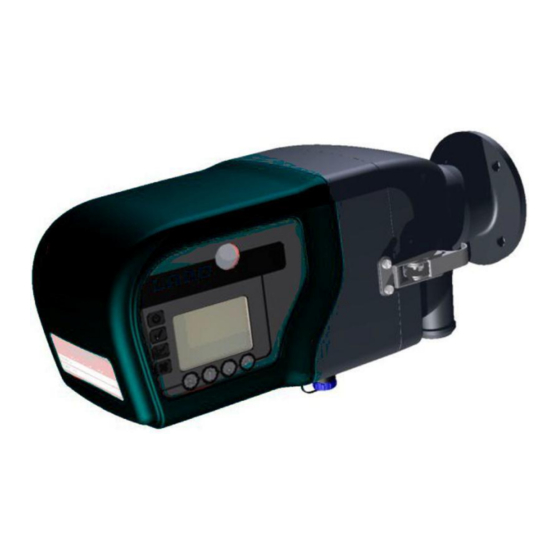
Page 54: Figure 21: Stack 710- Transceiver
The STACK 710 uses a novel method to compensate for such changes by using Flood LED (2) to illuminate both detectors ( and 7). Because it uses no focusing... -
Page 55: System Specification
STACK 710 6 Theory of Operation and Application 6.5.3 Calibration Check The Transceiver periodically performs a two-step calibration check. In the first step, a zero reflector (10), mounted on the outside of the Transceiver is placed into the optical beam. In the second step, the upscale filter (9) is also placed in the light path. - Page 56 6 Theory of Operation and Application STACK 710 Environmental Operating temperature: -20 to 55 °C / -4 to 131 °F (-40 °C / -40 °F with optional heater) Maximum Flue Gas 600 °C / 1112 °F temperature: Maximum Flange Temp: 200 °C / 392 °F...
-
Page 57: Maintenance
Maintenance Identifying Faults The STACK 710 Dust (opacity monitor) has been designed to assist the user in finding and correcting many possible problems. If the instrument detects a problem, it will switch off the Green System OK LED and de-energise the System OK relay. -
Page 58: Fault Number List
- Do not move either mechanism by hand or the precision gearbox may be irreparably damaged Note: When contacting ENVEA Service Department, please have the Instrument Type and Serial Number available. This will ensure a more accurate and efficient response. -
Page 59: Maintenance
STACK 710 7 Maintenance Maintenance The STACK 710 has been designed for a minimal amount of routine maintenance. To ensure a maximum monitor lifetime, however, the following maintenance schedule has been developed. Remember that the air purge system should always be left on, even if the boiler is off, to prevent any optics contamination. -
Page 60: Cleaning The Optical Surfaces
Transceiver Cover 7.5.1 Removing the cover If it is necessary to open the STACK 710 Transceiver cover, for example, to change communications option links or switches, proceed as follows: Figure 22: STACK 710- removing the cover. ENVEA UK Ltd... -
Page 61: Configuration Record Sheet
STACK 710 7 Maintenance Undo the eight screws (A). Pull the cover back about 50 mm (2”). Reach in and disconnect the touch panel connector (B) by pulling it towards the rear. Remove the cover completely. Replacing the cover 7.5.2 First, check that the sealing cord (D) is clean, evenly pressed down into its channel, continuous and undamaged. - Page 62 7 Maintenance STACK 710 Service History Date Action Part Replaced Part No. ENVEA UK Ltd (PC-000878-MA Issue 7, December 2021)
- Page 63 STACK 710 Notes: ENVEA UK Ltd (PC-000878-MA Issue 7, December 2021)
- Page 64 STACK 710 Notes: ENVEA UK Ltd (PC-000878-MA Issue 7, December 2021)
- Page 65 STACK 710 Notes: ENVEA UK Ltd (PC-000878-MA Issue 7, December 2021)
- Page 66 STACK 710 [This page is left blank intentionally.] ENVEA UK Ltd (PC-000878-MA Issue 7, December 2021)
-
Page 68: Envea Service And Support Centres
ENVEA Sales and Service engineers are available to consult regarding equipment suitability and technical support. To find a local ENVEA representative for your country or region, please contact us or visit our website www.envea.global ENVEA UK Ltd ENVEA House Rose &...
Need help?
Do you have a question about the STACK 710 and is the answer not in the manual?
Questions and answers