Sign In
Upload
Manuals
Brands
envea Manuals
Measuring Instruments
VIEW 373
envea VIEW 373 Manuals
Manuals and User Guides for envea VIEW 373. We have
1
envea VIEW 373 manual available for free PDF download: User Manual
envea VIEW 373 User Manual (61 pages)
Brand:
envea
| Category:
Measuring Instruments
| Size: 3 MB
Table of Contents
Table of Contents
5
Introduction
9
Purpose of this Manual
9
Product Safety
9
Danger from Process
9
Safety Procedures
9
Intended Use
11
Limits of Use
11
Additional Information
11
Product Serial Numbers
11
List of Abbreviations
11
Related Documentation
11
Product Parts and Options
12
Certification
12
Conformance and Related Standards
12
Technical Data
13
Process and Application Conditions
13
Sensor Specification
13
Dimensioned Drawings - Standard Sensor
14
Figure 1: Dimensional Drawing of VIEW 370_373 Sensor
14
Sensor Options
15
System Options
15
Cabling
16
Power Supply Cable Specification
16
Data Cable Specification
16
PC Software Suite (PC-ME DUST TOOLS)
17
System Description
18
Components
18
Sensor
18
Control Unit
18
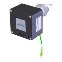
Figure 2: VIEW 370/373 X Sensor (with Grounding Strap)
18
Principle of Operation
19
Figure 3: Principle of Operation - Electrodynamic Sensors
19
Unpacking and Preparation
20
Unpacking and Inspection
20
Network Layouts
20
Prerequisites and Guidelines
20
Location Requirements
20
Cabling and Cable Routing
20
Grounding the Sensor
21
Sensor Installation
22
Safety Information
22
Mounting the Sensor
23
Fitting the Sensor to the Stack
23
Figure 4: Fitting the Sensor to the Stack (Example)
23
Connecting the Sensor
25
Sensor Connections
25
Electrical Connections (Power/Comms)
25
Figure 5: Sensor PCB Connections
25
Set Address Switch (SW100)
26
Set Sensor Comms Mode (SW101)
26
Basic System Setup
28
User Controls and Functionality
28
The Procontroller UI
28
Figure 6: Procontroller - User Interface with Controls
28
Standard Controller UI
29
Procontroller - Function Keys
29
Figure 7: Standard Controller - User Interface with Controls
29
Main Menu Screens
30
Other Symbols
31
Figure 8: Screen Elements (Example)
31
Initial System Checks
32
On Power-Up
32
Performing a Master Reset
32
Checking the Sensor Comms Mode
32
Adding Sensors to the Network
33
Detecting Sensors Automatically
33
Figure 9: Autodetect - Adding Sensors Automatically
33
Editing Basic Sensor Settings
34
Figure 10: Setup Screen - Sensor/System Settings
34
Figure 11: Basic Sensor Settings
34
Scaling Factor
35
Log Rates
35
Adjusting Log Rates
35
More Sensor Settings
35
Adding Sensors Manually
35
Editing Sensor/Device Settings
36
Deleting a Sensor/Device
36
Figure 12: more Settings - Sensor Settings Screen
36
Editing Settings for All Sensors/Devices at Once
37
Advanced Settings
37
Quality Assurance and Sensor Self-Tests
38
Introduction
38
Sensor Self-Tests
38
Running Self-Checks Manually
38
Figure 13: Quality Assurance (Qa)/Self Tests Screen
38
Zero and Span Checks
39
Short-Circuit Check (Contamination Check)
39
Self-Test Values (Pass Levels)
39
Disabling Self-Tests
39
Disabling Sensor Check Alarms
39
Comms Check
40
Maintenance
41
Safety Information
41
Maintenance Mode
41
Placing a Sensor in Maintenance Mode
42
Figure 14: Maintenance Mode Screen
42
Sensor Status
43
Service Messages
43
Figure 15: Sensor Status (List)
43
Clearing Service Messages
44
Inspecting and Cleaning the Sensor
44
Troubleshooting
46
Communication Failure
46
Checking Network Spurs
46
Power Loss
46
Frozen Readings
46
Sensor Reading too Low or too High
47
Appendix A- Scaling
48
Introduction
48
Calculating the Scaling Factor
48
Calibration Procedure
48
Using the Calibration Tool
49
Figure 16: Calibration Tool (with Direction of Editing)
49
Calculating the Scaling Factor
50
Appendix B- Menu Maps
51
Main Menu Screens
51
Figure 17: Menu Map - Main Menu Screens and Their Icons
51
Basic Sensor Setup
52
Figure 18: Menu Map - Basic Sensor Setup
52
More Sensor Settings
53
Figure 19: Menu Map - more Settings Menus
53
Basic System Setup
54
Figure 20: Menu Map - System Setup Menus
54
Other Functions
55
Figure 21: Menu Map - Other Functions Menus
55
Quality Assurance (QA) and Scaling
56
Figure 22: Menu Map - QA and Scaling Menus
56
General Notices
57
Compliance
57
Waste of Electrical and Electronic Equipment (WEEE) Directive (2012/19/EU)
57
Rohs Compliance Statement
57
List of Materials
57
Index
58
Envea Service and Support Centres
60
Advertisement
Advertisement
Related Products
envea VIEW 370
envea CAIRNET V2 2G/3G
envea CAIRNET V4
envea AirASafe 2 Ex
envea AirFlow P
envea CAIRNET
envea DensFlow
envea DensFlow HP
envea LAS 5000XD
envea M-Sens NIR
envea Categories
Measuring Instruments
Industrial Equipment
Monitor
Laser Level
Accessories
More envea Manuals
Login
Sign In
OR
Sign in with Facebook
Sign in with Google
Upload manual
Upload from disk
Upload from URL