Table of Contents

Related Manuals for envea DensFlow HP


Summary of Contents for envea DensFlow HP
- Page 1 OPERATING INSTRUCTIONS DensFlow HP FLOW MEASUREMENT FOR HIGH PRESSURE DENSE PHASE CONVEYING ENVEA Process GmbH - Gutedelstraße 31 – 79418 Schliengen - GERMANY Tel.: +49 (0) 7635 827248-0 / info.process@envea.global / www.envea.global...
-
Page 2: Table Of Contents
CONTENTS Page System overview ..........3 Function . -
Page 3: System Overview
1. System overview A measuring point consists of the following components: MSE 300 in the DIN Rail housing or field housing • Sensor for installation in the pipeline • C1-Box (optional) • C1-Box Sensor C1-Box MSE 300-FH 1 (+ 24 V) 2 (GND) 3 (A) 4 (B) -
Page 4: Function
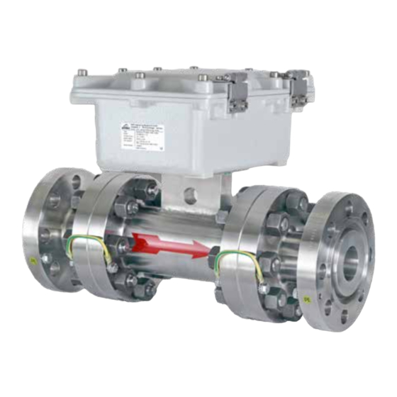
2. Function The DensFlow HP has been specially developed for the volume measurement of solids conveyed in • dense flow under high pressure, especially for use in coal gasification plants. DensFlow HP is working according to the latest microprocessor technology. By special capacitive linking •... -
Page 5: Safety
3. Safety The DensFlow HP measuring system has a state of the art, reliable design. It was tested and found to be in a perfectly safe condition when leaving the factory. Nevertheless, the system components may present dangers to personnel and items if they are not operated correctly. -
Page 6: Mounting And Installation
Mounting and installation 4.1 Supplied equipment MSE 300 in the DIN Rail or field housing • Sensor • Operating Instructions • C1-Box (optional) • 4.2 Required tools Appropriately sized spanner or ring spanner • Tools for electrical connections • 4.3 Mounting of the sensor The sensor has to be mounted as follows: Mounting in horizontal position is also possible. - Page 7 Attention! Before installing the sensor, it is essential to check whether in the transition range from pipe and • measuring pipe a burr, offset or seal extends into the free area. Possibly any protrusions in the pipe must be removed before mounting the sensor. It is always to ensure that the material enters the measuring tube continuously.
-
Page 8: Mounting The Evaluation Unit
4.4 Mounting of the Evaluation unit The Evaluation unit can be installed at a maximum distance of 300 m from the sensor. A cable of type “Ölflex Classic 110 CY” is recommended. The cable should be four wired, twisted and shielded. A minimum cable cross-section of 0.75 mm²... - Page 9 Fig. 8: Dimension of the MSE 300-FH (side view) 113 mm 125 mm 50 mm max. max. 13 mm 13 mm Fig. 9: Dimension of C1-Box...
-
Page 10: Use In Ex Hazardous Areas
4.5 Use in Ex hazardous areas Marking DustEx: II 3D Ex tc IIIC Dc - Equipment group: 2 - Equipment category: 3 - For combustible mixtures of air and dust - IP 65 - Maximum surface temperature 84 °C with Ta = 60 °C Marking GasEx: II 3G Ex dc ... -
Page 11: Electrical Connection
5. Electrical connection 5.1 Terminal layout MSE 300-FH Fig. 11: Electrical connection of the MSE 300-FH Evaluation unit Terminal No. Connection Connection of the power supply L / +24 V Input power supply 230 V / 50 Hz, 110 V / 60 Hz (optional 24 V DC) N / 0 V Input power supply 230 V / 50 Hz, 110 V / 60 Hz (optional 24 V DC) Protective Earth... -
Page 12: Terminal Layout Mse 300-Dr
5.2 Terminal layout MSE 300-DR Current output Current output Input Input - 4 ... 20 mA + 4 ... 20 mA Power supply Power supply 0 V DC + 24 V DC Not used Alarm relay Alarm relay Alarm relay NC (break contact) NO (make contact) Fig. -
Page 13: Electrical Connection C1-Box
5.3 Electrical connection C1-Box Sensor 1 Power supply + 24 V 2 Power supply 0 V 3 RS 485, Data A 4 RS 485, Data B S Shield Sensor 1 Evaluation unit Evaluation unit Power supply + 24 V 2 Power supply 0 V 3 RS 485, Data A 4 RS 485, Data B S Shield... -
Page 14: Operator Interface
6. Operator interface The MSE 300 is a multi-sensor Evaluation unit. It is therefore strongly recommended to check before commissioning whether the correct sensor is selected in menu System. The operator interface differs depending on the system design: DIN Rail housing without touchscreen, operation via PC software •... -
Page 15: Display
If no selection is made, the initialization disappears and the German language with a DensFlow HP sensor is selected. Initialization screen when the Evaluation unit in the field housing started first time. - Page 16 With the key [ I ] you can choose between different information Sensor status windows. In the first window the raw values for density [D] Value and flow rate [Q], the velocity [m/s], the current outputs [mA] 82892 and the quality [%] are displayed. 216787 The second window displays the error memory.
-
Page 17: Pc Interface
• Baud rate 9600, 8, E,1 • An RS 485 to USB adapter can be purchased from ENVEA Process. ✔ For the USB connection to the DIN rail version is a standard USB-A-B cable included. The USB connection is a point-to-point connection that is not BUS-capable. The ModBus address and... - Page 18 The edited data is transmitted to the Evaluation unit via “Device program”. Critical data concerning the ModBus communication and the calibration must be confirmed before the parameters are transmitted to the Evaluation unit: ✔ If, when saving the parameters in the Evaluation unit, the system calibration data is changed, this action must be confirmed by checking “Overwrite calibration”.
-
Page 19: Menu Structure
6.4 Menu structure The menu structure supports the user when adjusting the measuring range, the calibration, the measurement values and the choice of additional functions. In this connection, the numbering both on the display and in the PC interface is identical: 1. - Page 20 Deposit a calibration curve. Depending on the selection under 7.2.1 Calibration, the parameters to be entered are changing. EasyFlow calibration Conveyor type Selection: The DensFlow HP is only suitable for use in pneumatic pneumatic lines. Selection: 1 … 5 Calibration points Number of support points for a linearisation above the operating range.
- Page 21 Calibration Submenu 2.7.1 Value P1 Input: Measurement value Output measurement in the selected mass/time unit. 2.7.2 P1 - actual Display Display actually raw values for this calibration point. Input: Raw values 2.7.3 P1-Cal. Transfer of the current raw value (filtered) from the mass flow with the key [!].
- Page 22 EasyFull calibration Conveyor type Selection: The DensFlow HP is only suitable for use in pneumatic pneumatic lines. Calibration factor KK Input: 0.01 … 9.99 Factor for the subsequent adjustment of the actual measurement. All measurements are measured with this factor.
- Page 23 Input: Raw value Customer adjustment: Flow Separate calibration If the single calibration is selected, it is possible to set a linearisation on the bulk density and on the speed. This calibration option should only be performed by ENVEA Process trained personnel.
- Page 24 Alarm Settings for relay contacts Alarm type Selection: none: no alarm output on relay output MIN: min. alarm on relay output none / MIN / MAX / FLOW MAX: max. alarm on relay output FLOW: flow detection on relay output Input: 0 …...
- Page 25 Analog output Settings and calibration of analog output MIN limit Input: 0 … 22 mA Default settings: 3.2 mA MAX limit Input: 0 … 22 mA Default settings: 21 mA Alarm value Input: 0 … 22 mA Output value for sensor alarm. Default settings: 2 mA Alarm mode Selection:...
- Page 26 Analog output 2 Submenu 4.8.1 Output variable Selection: Q / V / D Q: Throughput output at the analog output V: Speed output at the analog output D: Density output at the analog output 4.8.2 Calibration 4 mA Selection: The current output can be set via key Set output current functions and adjusted at the receiving end.
- Page 27 Pulse output Passive signal for pulse cleaning or output of a totaliser. Selection: None / Function cleaning / quantity None: no pulse output Cleaning: possibility to control a solenoid valve for compressed air-fluid. 5.4 Pulses / Unit without function. Quantity: the quantity is send as an impulse sequence to the output;...
- Page 28 Analog input Possibility of autocorrection via external current signal. The connection of the current input is not galvanically isolated. If the connection is incorrect, the CPU of the Evaluation unit can be destroyed. An external galvanic isolation, by current disconnector or similar shall be provided. Input calibration 4 mA Selection: Calibrate 4 mA input...
- Page 29 Selection: EasyFlow / EasyFlow: calibration via known throughput 7.2.1 Calibration EasyFull / separate EasyFull: calibration via empty- and full- calibration Separate: calibration for ENVEA Process trained personnel Selection: 7.2.2 Sensor The Evaluation unit verifies the availability of SolidFlow 2.0 / Paddy /...
- Page 30 7.3.5 Contrast Input: 0 … 100 % In the case of display exchange, the contrast can be changed via the PC software, if necessary. Address Input: 1… 255 ModBus address of Evaluation unit, if operated on a PLC or PC as a slave. Selection: Baud rate Communication speed of the Evaluation unit...
-
Page 31: Start-Up Procedure
Only according to instructions from personnel of ENVEA Process: If a detailed error analysis is necessary, a copy of all ModBus registers can be stored as a text file in the installation folder of the software by clicking on the sensor dump. -
Page 32: Easyflow Calibration
7.1 EasyFlow calibration The EasyFlow calibration calibrates the sensor to a known throughput. Every calibration point should be use at different mass flow, so the sensor can calculate a linearisation between this points. If there is no opportunity for two different calibration points, the system use a virtual zero point. -
Page 33: Datalogger Function In The Software
For the calibration of density and speed up to five calibration points can be set. Under 2.8.n Calibration point, the loading of the sensor in % is now specified and assigned to the appropriate raw value in 2.8.n Raw value. Subsequently, the same procedure is performed with the speed calibration. -
Page 34: Adjusting The Measurement Values
A zero offset is in most cases a process problem, for example caking in the measuring tube. For processes with caking materials, there is the possibility of a cleaning flange. Please get in contact with ENVEA Process for more information. -
Page 35: Error Signalling
8. Error signalling For monitoring the availability a wide range of functions for self-diagnostics were integrated, in order to signal various errors: 1. Fatal Error (ERR): Fatal Errors (ERR) always set the current output to the set alarm value. Technical problems or problems with the complete system are displayed on the touchscreen. -
Page 36: Maintenance
1 year from the date of delivery. In the event of a defect during the warranty period, defective components will be replaced or repaired at ENVEA Process plant free of charge as considered appropriate. Replaced parts will become ENVEA Process property. -
Page 37: Error Codes System
11.1 Error codes system CODE DIN Rail Current Cause Action flashing output S:E0002 2 mA Defective data bus Turn power off / on. If not helpfully sensor exchange. S:E0004 2 mA Defective data bus Turn power off / on. If not helpfully sensor exchange. S:E0010 2 mA Loading measuring is not plausible... -
Page 38: Error Codes Velocity
Check loading and velocity parameter status of motion detection PROC Q:P2000 4…20 mA Empty buffer Wait for some minutes otherwise turn power off / on A detailed error description and following troubleshooting can be carried out by trained ENVEA Process technicians. -
Page 39: Connection Example Digital Output
12. Connection example digital output Open Collector Open: 0 V Closed: Ub - 0.7 V Closed: Ub - 0.7 V Open: Ub Closed: 0.7 V Closed: 0.7 V Open Collector R = (Ub - 0.7 V)/l... -
Page 40: Technical Data
Data backup Flash memory Pulse output Open Collector - max. 30 V, 20 mA ENVEA Process GmbH Gutedelstraße 31 · 79418 Schliengen (Germany) Fon +49 7635 827248-0 · Fax +49 7635 827248-48 · www.envea.global PART OF THE ENVEA GROUP EN 03/08/2020...
Need help?
Do you have a question about the DensFlow HP and is the answer not in the manual?
Questions and answers