
Related Manuals for envea LAS 5000XD


Summary of Contents for envea LAS 5000XD
- Page 1 TECHNICAL MANUAL LAS 5000XD Cross Duct Tunable Laser Gas Analyzer – DECEMBER 2022 – 111, Boulevard Robespierre, 78300 POISSY – TEL. 33(0)-1.39.22.38.00 http://www.envea.global...
- Page 2 WARNING! INVISIBLE LASER RADIATION! The LAS 5000XD uses lasers emitting light in the near-infrared region of the spectrum. When installed on a duct or stack, the LAS 5000XD is classified as a Class 3R or 3B laser product. WARNING! QUALIFIED PERSONNEL ONLY! Electrical work must be carried out only by suitably trained and qualified personnel.
- Page 3 THE DUCT FLANGE 3.1.2.1. Duct flange requirements 3.1.2.2. Duct flange alignment – angle 3.1.2.3. Duct flange alignment – offset 3.1.3. INSTALLATION AND COMMISSIONNING THE LAS 5000XD 3.1.3.1. Tools required 3.1.3.2. Preliminary mounting operations 3.1.3.3. Preliminary alignment using alignment tools 3.1.3.4.
- Page 4 OTHER CHECKS 4.3. ANALOG INPUT/OUTPUT CONFIGURATION 4.3.1. ANALOG OUTPUT CONFIGURATION 4.3.2. ANALOG INPUTS CONFIGURATION 4.4. MAINTENANCE KITS ABBREVIATIONS APPENDIX 6.1. MODBUS MAPPING 6.1.1. GLOSSARY 6.1.2. FUNCTIONS CODES 6.1.3. MODBUS MAPPING 6.2. ERROR CODES 6.2.1. LAS 5000XD DISPLAY ERROR CODES DECEMBER 2022...
- Page 5 Table 1-2 – Connector identification of the feed-through junction block Table 6-1 – Modbus mapping LIST OF FIGURES Figure 1–1 – Presentation of the LAS 5000XD Figure 1–2 – LAS 5000XD overview Figure 1–3 – Internal view of the Junction box Figure 1–4 –Junction box dimensions...
- Page 6 Duplication prohibited Limits of use To achieve optimum performance and safe operation of the LAS 5000XD, keep within the limits detailed in the technical specifications section of this manual (Section 1.2). Operation outside of these limits can result in failure to achieve the performance required and can cause damage to the equipment.
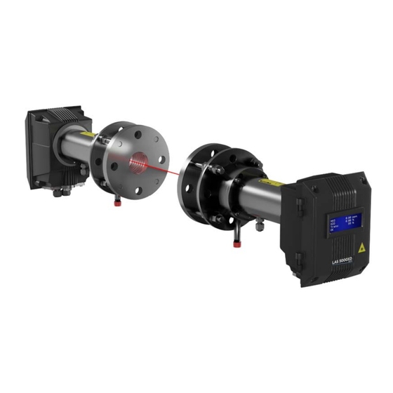
- Page 7 Duplication prohibited GENERAL - CHARACTERISTICS Read this manual before installing the LAS 5000XD. Follow all instructions to ensure that the LAS 5000XD works to specification and to avoid damaging the LAS 5000XD. Figure 1–1 – Presentation of the LAS 5000XD...
- Page 8 The LAS 5000XD monitors gas concentration quantitatively using Tunable Diode Laser Absorption Spectroscopy. The LAS 5000XD measures the target gas directly in a duct or stack. Therefore, there is no need for sample extraction or conditioning, and no need to transport gas to the LAS 5000XD.
- Page 9 1.1.3. OPERATING MODES The LAS 5000XD has two operating modes: standard mode and align mode. At any time, the user can switch from the standard mode to the align mode by clicking on the fast mode button in the Alignment page of the Web Server.
- Page 10 LAS 5000XD ENVEA Duplication prohibited – Terminal block label of ESTEL module for J3 and J2 connectors (12). – 100-230 VAC mains connection cable to 24 VDC power supply (13). – 24 VDC cable (14). – 100-230 VDC mains cable (15).
- Page 11 LAS 5000XD ENVEA Duplication prohibited Table 1-1 – Identification of AI/AO on J3 and J2 terminal block of ESTEL module Table 1-2 – Connector identification of the feed-through junction block Connector Connection 0V DC 0V DC +24V DC +24V DC...
- Page 12 LAS 5000XD ENVEA Duplication prohibited Junction box dimensions : Length : 321 mm Width : 273 mm Height : 172 mm Weight : 4.0 kg Figure 1–4 –Junction box dimensions DECEMBER 2022...
- Page 13 LAS 5000XD ENVEA Duplication prohibited 1.1.4.2. Audit Cell The Audit-Cell is presented below : (1) Temperature sensor connection, (2) span gas inlet, (3) span gas outlet Figure 1–5 – Audit-Cell presentation The span gas inlet or outlet can be either on the transmitter side or the receiver side, the direction is not important.
- Page 14 LAS 5000XD ENVEA Duplication prohibited 1.1.4.3. In-line span check cell The in-line span cell should be inserted between the Receiver and the alignment bellow. It is presented below : (1) Window, (2) gas in, (3) gas out, (4) gasket Figure 1–7 – Unfitted in-line span cell...
- Page 15 LAS 5000XD ENVEA Duplication prohibited 1.2. CHARACTERISTICS 1.2.1. TECHNICAL CHARACTERISTICS The technical characteristics are defined in the following conditions : – Gas temperature : 25°C – Gas pressure : 1013 mbar – Path length : 100 cm Ambient temperature : 25°C –...
- Page 16 LAS 5000XD ENVEA Duplication prohibited : 15 W when starting-up the LAS 5000XD Power consumption : < 15 W in normal operation Recommended T°C : - 20°C to + 55°C IP index Tx & Rx enclosures : IP65 Flange specification requirement on : DN50 PN16, 2’’...
- Page 17 1.2.3.2. Handling and storage The LAS 5000XD needs to be handle with care to avoid damage. If either the Transmitter or Receiver are removed from the alignment bellows, the exposed window aperture should be protected and kept clean. The exposed window location is indicated in Figure 1–9.
- Page 18 LAS 5000XD ENVEA Duplication prohibited Transmitter dimensions Receiver dimensions Figure 1–10 – LAS 5000XD dimensions DECEMBER 2022...
- Page 19 The light emitted from a single-mode laser source is directed through the gas to be measured. As the laser frequency is tuned, the intensity of light received by the LAS 5000XD Receiver varies depending on the concentration, temperature and pressure of the targeted gas.
- Page 20 Absorption spectra contain a large amount of information about the gas being measured and, importantly, about the quality of the measurement, enabling the health of the LAS 5000XD to be continuously monitored. The standard deviation of the residual of the recorded spectrum and the fitted lineshape is a key indicator of the measurement quality.
- Page 21 Duplication prohibited OPERATING INSTRUCTIONS 3.1. INITIAL STARTUP The LAS 5000XD is checked and calibrated in the factory before delivery. However, some parameters must be checked on-site when starting-up the analyzer to ensure correct operation. 3.1.1. CHOOSING THE INSTALLATION LOCATION When choosing an installation location for the LAS 5000XD, it is necessary to make sure: −...
- Page 22 LAS 5000XD ENVEA Duplication prohibited 3.1.2. THE DUCT FLANGE It is recommended that duct flange work is carried out when the process is off. 3.1.2.1. Duct flange requirements The dimensions of the duct flange are the following (see Figure 3–1): –...
- Page 23 LAS 5000XD ENVEA Duplication prohibited Pay attention to mount the flange with the holes oriented as rhomb. If it is not the case, the analyzer will not be upright, and the optional weather protection cover cannot be mounted. CORRECT MOUNTING : mounting holes oriented as rhomb.
- Page 24 LAS 5000XD ENVEA Duplication prohibited 3.1.2.2. Duct flange alignment – angle The initial installation of the duct flanges is very important. The flanges should be aligned as precisely as possible. Consequently, the following installation recommendations should be respected: − The duct flanges should be in-line and parallel.
- Page 25 It is recommended to avoid offsetting the duct flanges and to maximize the clear view from one aperture to the other. If the duct flanges are offset, the maximum amount of light received by the Receiver will be limited, leading to poor LAS 5000XD performance. Legend: Explanation...
- Page 26 INSTALLATION AND COMMISSIONNING THE LAS 5000XD 3.1.3.1. Tools required The tools required for the LAS 5000XD installation and commissioning are the following: – 3 mm Alen key for the bolts that attach the cable gland plate, and 5 mm for the bolts on the alignment bellows.
- Page 27 Figure 3–6 – Mounting the alignment bellows on the duct flange General purging advices: A constant gas purge is necessary at all times to keep the LAS 5000XD process windows free of process dust and to maintain the maximum light Constant gas purge: throughput.
- Page 28 LAS 5000XD ENVEA Duplication prohibited Window purge setup: Figure 3–7 – Window purge setup DECEMBER 2022...
- Page 29 Outlet air pressure gauge (Left, in above image) ACCAIR-FFRA air filter regulator. Provides a ACCAIR-FFRA constant flow of filtered instrument air to the LAS 5000XD. Requires additional flow control. (Right, in above image) ACCAIR-FFRC air filter regulator with flow control. Provides a constant flow of filtered instrument air and also takes...
- Page 30 LAS 5000XD ENVEA Duplication prohibited 3.1.3.3. Preliminary alignment using alignment tools Mounting the alignment tools on the alignment flanges: The preliminary alignment has to be done with the alignment tools delivered with the transmitter and the receiver. These tools consist of two different discs equipped with a torch light (light source) (1) for one and an aiming device (2) for the other (see Figure 3–8).
- Page 31 LAS 5000XD ENVEA Duplication prohibited (1) Torch light, (2) aiming device, (3) transmitter alignment flange, (4) alignment bellows, (5) bolts, (6) receiver alignment flange, (7) alignment bellows, (8) bolts. Figure 3–8 – Mounting the alignment tools on the alignment flanges (1) transmitter side, (2) receiver side.
- Page 32 LAS 5000XD ENVEA Duplication prohibited Carrying out the preliminary alignment: This operation should be carried out very precisely. It consists in aligning the light beam from the light source to the center of the aiming device using the alignment nuts of the alignment bolts placed above the alignment bellows (1) .
- Page 33 LAS 5000XD ENVEA Duplication prohibited (1) Alignment bellows, (2) alignment nuts, (3) aiming device, (4) light source, (5), (6), (7), (8) nuts, (9) correct target of the aiming device. Figure 3–10 – Preliminary alignment procedure DECEMBER 2022...
- Page 34 LAS 5000XD ENVEA Duplication prohibited 3.1.3.4. Mounting the analyzer (transmitter and receiver) NOTE : Before mounting the analyzer on the alignment flanges above the bellows, it is necessary to remove the alignment tools. Mounting the Transmitter: The transmitter should be mounted on the torch light side.
- Page 35 LAS 5000XD ENVEA Duplication prohibited 3.1.3.5. Electrical connecting the analyzer When preliminary alignment is complete and the Transmitter and Receiver have been mounted, begin working with electrical connections. The cable specifications are indicated in section 1.2.1.4. Cables must be connected to connection devices with protection mode listed in EN/IEC 60079-0.
- Page 36 LAS 5000XD ENVEA Duplication prohibited Transmitter electrical connection: – With the 3 mm Alen Key, unscrew and remove the 4 screws (1) keeping in place the transmitter fitting plate, and remove the plate. Loosen the four screws (2) holding closed the transmitter door and open the door.
- Page 37 LAS 5000XD ENVEA Duplication prohibited Receiver electrical connection: – With the 3 mm Alen Key, unscrew and remove the 4 screws (1) keeping in place the receiver fitting plate, and remove the plate. Loosen the four screws (2) holding closed the receiver door and open the door.
- Page 38 LAS 5000XD ENVEA Duplication prohibited Transmitter (slave)-Receiver (master) electrical connections The overview diagram shown below enables the user to have a global view of the transmitter (slave) receiver (master) electrical connections. (1) Transmitter (slave), (2) Receiver (master), (5) Receiver (master) - transmitter (slave) connection (RJ50), (6) Ethernet connection (RJ45), (7) 24V power supply + Modbus RTU connection, (8) USB Estel (AI/AO) connection.
- Page 39 LAS 5000XD ENVEA Duplication prohibited Analyzer connection to the 24V power supply: WARNING! QUALIFIED PERSONNEL ONLY! Electrical work must be carried out only by suitably trained and qualified personnel. There are two possibilities for connecting the analyzer to the 24V power supply: –...
- Page 40 LAS 5000XD ENVEA Duplication prohibited DO NOT modify the connections on J2 and J3. (1) Power / Modbus RTU cable, (2) USB ESTEL cable, D01-4065: Modbus cable, D01-4073: relay, concentration, power supply cable, D01-4074 : pressure, temperature cable Figure 3–17 – Junction box connections Analog outputs (8-11) supply current to the loop.
- Page 41 WARNING! INVISIBLE LASER RADIATION! The LAS 5000XD uses lasers emitting light in the near-infrared region of the spectrum. When installed on a duct or stack, the LAS 5000XD is classified as a Class 3R et 3B laser product. The analyzer supports 24V only Without the junction box, connect the 24V power supply of the analyzer to the mains of the site.
- Page 42 LAS 5000XD ENVEA Duplication prohibited The analyzer will start up 2min30 secs after powering on. Please, wait for it. At startup, the screen display shows the following information: Gas and Light Transmission Values Modbus and Software version IP Addresses and Mask...
- Page 43 LAS 5000XD ENVEA Duplication prohibited Then, input 192.168.1.5:5000 in the address bar to connect to the WebServer. The home page is displayed as follows: Click on the “Settings” button , then on the “Communication” button to display this sub-menu. Change the IP address of the analyzer with static mode selected, or switch to DHCP mode if DHCP server is available.
- Page 44 This is the second step of the alignment started in section 3.1.3.3, and have to be done when the duct is running. Make sure the LAS 5000XD is working on a live process before carrying out the second alignment. The WebServer final alignment allows to define the Reference Power of the laser beam (i.e. the maximum Optical Power value of the laser) and to set it in the WebServer.
- Page 45 LAS 5000XD ENVEA Duplication prohibited When the maximum value of the receiver is reached, click on the “Set Trans.” button – record this value as Reference Power in the corresponding field of the home page which will indicate a 100% Transmission.
- Page 46 WEBSERVER DESCRIPTION The LAS 5000XD uses an HMI (Human Machine Interface) software, named WebServer, for a number of tasks, including aligning the Transmitter and Receiver, setting up the LAS 5000XD, logging data to a file, and diagnostics. The WebServer home page is shown below. The instant value of the concentration measures in the selected unit is displayed at the top of all the pages, and the user just needs to click on the browsing button to display the corresponding page.
- Page 47 Page name Function (used to) This button allows the user to load the technical Technical manual manual of the LAS 5000XD in the download file. It gives the information necessary to identify the Information panel analyzer and to communicate with.
- Page 48 LAS 5000XD ENVEA Duplication prohibited 3.2.1. HOME PAGE The user displays this page by clicking on which becomes This page displays the current operating and measurement parameter values of the analyzer. As they are on grey background, these values cannot be modified by the user.
- Page 49 LAS 5000XD ENVEA Duplication prohibited OUTSIDE PATH section : Since the gas is only measured along the laser path length through the stack, and the total laser path length is longer because of the flanges, the transmitter and the receiver, it is necessary to take into account the laser path length of the flanges, the transmitter and the receiver on both sides and remove it for the concentration calculation.
- Page 50 LAS 5000XD ENVEA Duplication prohibited 3.2.2. ALIGNMENT PAGE The user displays this page by clicking on which becomes This page displays the current value of the laser optical power (1) and enables to carry out the second alignment. The curves represent the Optical power detected by the receiver as a function of the laser current stated in point number (Data points).
- Page 51 LAS 5000XD ENVEA Duplication prohibited 3.2.3. RECORDS PAGE The user displays this page by clicking on which becomes By default, this page displays in continuous the current concentration values of the gases being sampled. During data acquisition, the analyzer stores the data in four different databases: “Seconds”, “Hours”, “Days”...
- Page 52 LAS 5000XD ENVEA Duplication prohibited The user zooms out by left double-clicking anywhere in the graph. DECEMBER 2022...
- Page 53 LAS 5000XD ENVEA Duplication prohibited 3.2.4. DIAGNOSTICS PAGE The user displays this page by clicking on which becomes By default, this page displays in continuous the current concentration values of the gases being sampled, the optical power of the laser, the pressure and the temperature in the stack between the two flanges.
- Page 54 LAS 5000XD ENVEA Duplication prohibited 3.2.5. SPECTRA The user displays this page by clicking on which becomes This page gives a plot of the laser radiation spectrum emitted by the transmitter (Transmission) and the measurement acquired at the receiver (Measurement) as a function of the relative wave number.
- Page 55 LAS 5000XD ENVEA Duplication prohibited 3.2.6. CONFIGURATION The user displays this page by clicking on which becomes gives access to configurable sub-menus: Gas measurement, Communication, 4-20 mA, Audit Cell mode, Software update, Engineer. 3.2.6.1. Gas Measurement The user displays this sub-menu by clicking on which becomes .
- Page 56 LAS 5000XD ENVEA Duplication prohibited These parameters are set in factory before delivery and it is strongly advised not to modify them. If the pathlength is modified, that will modify completely the metrology. NH3 (gas 1) and H2O (gas 2) sections : it allows to manage the parameters of the gas measurement.
- Page 57 LAS 5000XD ENVEA Duplication prohibited 3.2.6.2. Communication The user displays this sub-menu by clicking on which becomes . It allows to manage the network and Modbus RTU communications. NETWORK section: it allows the automatic network configuration. The MODE field allows to select the STATIC or DHCP mode: –...
- Page 58 LAS 5000XD ENVEA Duplication prohibited 3.2.6.3. 4-20 mA and analog input/output configuration The user displays this sub-menu by clicking on which becomes . It allows to configure the analog inputs / outputs. ANALOG INPUT RANGE POINT section: it allows to configure the analog inputs according to the specific range of the temperature and pressure sensors.
- Page 59 LAS 5000XD ENVEA Duplication prohibited ANALOG INPUT/OUTPUT CONFIGURATION: The analog inputs are assigned to the temperature and pressure measurement. They are configured in factory before delivery, and they shouldn’t be modified. DECEMBER 2022...
- Page 60 LAS 5000XD ENVEA Duplication prohibited 3.2.6.4. Audit Cell Mode The user displays this sub-menu by clicking on which becomes . The audit cell is an optional device allowing to easily check the accuracy of the measurements given by the analyzer. It is mounted outside the stack and is completely independent from its fluid circuit.
- Page 61 LAS 5000XD ENVEA Duplication prohibited – CLEAR BACKGROUND button it allows to cancel the background values. Consequently, the measurement is not fitted anymore. – FACTORY BACKGROUND RESET button : it allows to recover the values set in factory before delivery.
- Page 62 The user displays this sub-menu by clicking on which becomes . This access is for ENVEA Service Engineers only. 3.2.7. MANUAL LOADING The user loads the technical manual of the LAS 5000XD by clicking on which becomes when loading is achieved. DECEMBER 2022...
- Page 63 LAS 5000XD ENVEA Duplication prohibited 3.2.8. INFORMATION PAGE The user displays this page by clicking on which becomes . It gives the information necessary to identify the analyzer and to communicate with. The identification information is as follows : the analyzer name with the gas type to be analyzed, its serial number, the firmware version which performs calculations and its build time (i.e.
- Page 64 Duplication prohibited 3.3. CALIBRATION The LAS 5000XD is set up at the factory to measure and report concentration correctly. To check the accuracy of the LAS 5000XD, there are two available methods: an in-line span check cell or an audit cell.
- Page 65 Gas inlet and outlet connections are fitted on the audit cell flanges (A, C, in the image below). All gas fittings are ¼” Swagelok. Optional gas fittings, for purging the outside path between the Transmitter / Receiver and cell windows are also located on the LAS 5000XD flanges. Legends: –...
- Page 66 IN-LINE SPAN CHECK CELL To check the operation and response of the LAS 5000XD an in-line span cell can be used. A known gas concentration is injected into the cell and adds a fixed offset to the reported process concentration. Only non-flammable and non-corrosive gases should be introduced into the in-line span check cell to prevent damage and to prevent a flammable risk.
- Page 67 LAS 5000XD. Check the alignment of the LAS 5000XD after installing the in-line cell, see sections 3.1.3.3 and 3.2.2. The recommended tools for mounting the in-line span cell are the followings : –...
- Page 68 3-way valve as required. The time interval between span checks can vary and for assistance please contact your local ENVEA representative. The span cell should be purged with instrument air for a minimum of 15 minutes after the final span check.
- Page 69 – Repeat steps four and five until the window is clean. If this method does not remove contaminants, replace the window. Contact ENVEA or your local ENVEA representative. Figure 4–1 – Window cleaning...
- Page 70 Duplication prohibited 4.2. OTHER CHECKS WARNING! INVISIBLE LASER RADIATION! The LAS 5000XD uses lasers emitting light in the near-infrared region of the spectrum. Power off the LAS 5000XD before disassembling it in any way. Step Details Reference Over time, due to external factors, the Transmitter and Receiver’s alignment can change.
- Page 71 LAS 5000XD ENVEA Duplication prohibited 4.3. ANALOG INPUT/OUTPUT CONFIGURATION 4.3.1. ANALOG OUTPUT CONFIGURATION The analog outputs are assigned to the gas concentration measurement. They are configured to convert the concentration measurements into 4-20 mA signals and allow the data numeric communication. By default, the analog output 1 is configured for the gas n°1, and the analog output n°2 is configured for...
- Page 72 LAS 5000XD ENVEA Duplication prohibited 2 – Setting the analog output 1 to 20 mA, i. e. the maximum value of the gas concentration range In the ANALOG OUTPUT 1 section, set the TEST MODE field to ON and click on the button to confirm.
- Page 73 LAS 5000XD ENVEA Duplication prohibited 4.3.2. ANALOG INPUT CONFIGURATION See Figure 4–4. The analog inputs 16 and 17 of the JUNCTION BOX are assigned to the temperature measurements, and the analog inputs 18 and 19 are assigned to the pressure measurements (1). They are configured to convert the values obtained from the temperature and pressure sensors into 4-20 mA signals, in order to be taken into account and processed by the system.
- Page 74 LAS 5000XD ENVEA Duplication prohibited to decrease or increase the value of the MAX ADC VALUE field until reaching the maximum of the full scale, i.e. 2.5000 bar here. Then click on to confirm. Carry out a mid-scale check. Set the 4-20 mA current generator to 12 mA, and check that the value –...
- Page 75 LAS 5000XD ENVEA Duplication prohibited 4.4. MAINTENANCE KITS Maintenance kits are as follows: Maintenance LAS 5000XD : Line Nb Designation Reference M6 socket screw 25 mm G07-CC-06-025-I O-ring G06-044_0-2_3-S M3 socket screw 8 mm G07-CC-03-008-I Gasket for gland plate P06-4021-D...
- Page 76 LAS 5000XD ENVEA Duplication prohibited ABBREVIATIONS Accessory Note Percentage °C Degrees Celsius Analog input Analog output ASME American Society of Mechanical Engineers Communications British standard pipe Hertz Received optical intensity Transmitted optical intensity Kilogram Path length Liquid crystal display Light emitting diode...
- Page 77 LAS 5000XD ENVEA Duplication prohibited APPENDIX 6.1. MODBUS MAPPING The official Modbus specification can be found at www.modbus.org/specs.php. 6.1.1. GLOSSARY Parameter Description Address Integer address of the location in the memory map (word format => 2 bytes) Read-only parameter Read/write parameter...
- Page 78 LAS 5000XD ENVEA Duplication prohibited 6.1.3. MODBUS MAPPING – Parameters using multiple registers must be read, or written to, with a single command. The LAS 5000XD reports an error if registers are read, or written to, with multiple commands. –...
- Page 79 LAS 5000XD ENVEA Duplication prohibited Size Number Minimum Maximum Start Access Data Parameter Description Example value value Address modbus allowed allowed registers Gas temperature min Gas temperature min 2013 2014 Float ADC value ADC value Gas temperature max Gas temperature max...
- Page 80 LAS 5000XD ENVEA Duplication prohibited Size Number Minimum Maximum Start Access Data Parameter Description Example value value Address modbus allowed allowed registers Gas n°1 concentration Gas n°1 concentration 3028 3029 Float offset offset Unsigned Gas n°1 rolling Gas n°1 rolling...
- Page 81 LAS 5000XD ENVEA Duplication prohibited Size Number Minimum Maximum Start Access Data Parameter Description Example value value Address modbus allowed allowed registers Analog output n°2 min Analog output n°2 min 4107 4108 Float 4000 DAC value DAC value Analog output n°2 Analog output n°2...
- Page 82 LAS 5000XD ENVEA Duplication prohibited Size Number Minimum Maximum Start Access Data Parameter Description Example value value Address modbus allowed allowed registers 5100 5109 String Date Date 5110 5119 String Time Time DECEMBER 2022...
- Page 83 Duplication prohibited 6.2. ERROR CODES 6.2.1. LAS 5000XD DISPLAY ERROR CODES The following errors appear on the display of the LAS 5000XD: Error nb Message displayed “Error : Slave unit not responding (1)” “Error : UDP listener (2)” “Error : MODBUS (4)”...
- Page 84 LAS 5000XD ENVEA Duplication prohibited Page intentionally left blank DECEMBER 2022...
Need help?
Do you have a question about the LAS 5000XD and is the answer not in the manual?
Questions and answers