Table of Contents
Advertisement
Quick Links
www.ti.com
User's Guide
LMQ61460EVM-400K User's Guide
Sam Jaffe
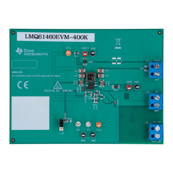
The LMQ61460-Q1 evaluation module (EVM) is designed to help customers evaluate the performance of the
LMQ61460-Q1 synchronous step-down voltage converter. This EVM implements the LMQ61460-Q1 in a 14-pin
wettable flanks Hotrod
™
6-A load current switching at 400 kHz with exceptional efficiency and output accuracy in a very small solution
size. The EVM provides multiple power connectors and test points. In addition to an optimized EMI board layout,
the LMQ61460-Q1 utilizes integrated bypass capacitors which results in great EMI performance.
CONVERTER
U1
SNVU698B – SEPTEMBER 2020 – REVISED DECEMBER 2020
Submit Document Feedback
package, as shown in
Table
Table 1-1. Device and Package Configurations
IC
LMQ61460-Q1
Figure 1-1. LMQ61460EVM-400K Top View
Copyright © 2021 Texas Instruments Incorporated
1-1. It is capable of delivering 5-V output voltage and up to
PACKAGE
14-pin wettable flanks Hotrod package 4.0 mm × 3.5 mm × 1.0 mm
LMQ61460EVM-400K User's Guide
1
Advertisement
Table of Contents

Subscribe to Our Youtube Channel
Related Manuals for Texas Instruments LMQ61460EVM-400K


Summary of Contents for Texas Instruments LMQ61460EVM-400K
- Page 1 CONVERTER PACKAGE LMQ61460-Q1 14-pin wettable flanks Hotrod package 4.0 mm × 3.5 mm × 1.0 mm Figure 1-1. LMQ61460EVM-400K Top View SNVU698B – SEPTEMBER 2020 – REVISED DECEMBER 2020 LMQ61460EVM-400K User's Guide Submit Document Feedback Copyright © 2021 Texas Instruments Incorporated...
-
Page 2: Table Of Contents
7 Bill of Materials..................................8 Revision History................................... Trademarks Hotrod ™ is a trademark of Texas Instruments. All trademarks are the property of their respective owners. LMQ61460EVM-400K User's Guide SNVU698B – SEPTEMBER 2020 – REVISED DECEMBER 2020 Submit Document Feedback Copyright © 2021 Texas Instruments Incorporated... -
Page 3: Introduction
For a quick reference, Figure 1-1 shows the pin configuration of the LMQ61460-Q1. 4 mm AGND Figure 1-1. LMQ61460-Q1 Pin Configuration (Top View) SNVU698B – SEPTEMBER 2020 – REVISED DECEMBER 2020 LMQ61460EVM-400K User's Guide Submit Document Feedback Copyright © 2021 Texas Instruments Incorporated... -
Page 4: Quick Start Guide
2.1 MHz. Figure 5-1 for connector locations. CAUTION Caution Hot surface. Contact may cause burns. Do not touch. LMQ61460EVM-400K User's Guide SNVU698B – SEPTEMBER 2020 – REVISED DECEMBER 2020 Submit Document Feedback Copyright © 2021 Texas Instruments Incorporated... -
Page 5: Detailed Descriptions
IC turns on by default. Populate RENB to adjust UVLO. Apply a voltage to EN to externally enable or disable the device. SNVU698B – SEPTEMBER 2020 – REVISED DECEMBER 2020 LMQ61460EVM-400K User's Guide Submit Document Feedback Copyright © 2021 Texas Instruments Incorporated... - Page 6 This connector is provided for measuring the output voltage accurately. VINS VIN sense This connector is provided for measuring the input voltage accurately. LMQ61460EVM-400K User's Guide SNVU698B – SEPTEMBER 2020 – REVISED DECEMBER 2020 Submit Document Feedback Copyright © 2021 Texas Instruments Incorporated...
-
Page 7: Schematic
For more information regarding this topic, reference the EMI Filter Components and Their Nonidealities for Automotive DC/DC Regulators Technical Brief. SNVU698B – SEPTEMBER 2020 – REVISED DECEMBER 2020 LMQ61460EVM-400K User's Guide Submit Document Feedback Copyright © 2021 Texas Instruments Incorporated... -
Page 8: Alternative Bom Configurations
24.9 kΩ 6.04 kΩ 3 x 22 µF 2 x 4.7 µF + 2 x 1 µH (XEL5030) 100 nF LMQ61460EVM-400K User's Guide SNVU698B – SEPTEMBER 2020 – REVISED DECEMBER 2020 Submit Document Feedback Copyright © 2021 Texas Instruments Incorporated... -
Page 9: Board Layout
Test points have been provided for ease of use to connect the power supply and required load, and to monitor critical signals. The board measures 3.00" x 4.00" (76mm x 101mm). Figure 5-1. Top View with Silkscreen SNVU698B – SEPTEMBER 2020 – REVISED DECEMBER 2020 LMQ61460EVM-400K User's Guide Submit Document Feedback Copyright © 2021 Texas Instruments Incorporated... - Page 10 Board Layout www.ti.com Figure 5-2. Top Layer Figure 5-3. Signal Layer 1 - Ground Plane LMQ61460EVM-400K User's Guide SNVU698B – SEPTEMBER 2020 – REVISED DECEMBER 2020 Submit Document Feedback Copyright © 2021 Texas Instruments Incorporated...
- Page 11 Board Layout Figure 5-4. Signal Layer 2 - Routing Figure 5-5. Bottom Layer SNVU698B – SEPTEMBER 2020 – REVISED DECEMBER 2020 LMQ61460EVM-400K User's Guide Submit Document Feedback Copyright © 2021 Texas Instruments Incorporated...
-
Page 12: Lmq61460Evm-400K Board Test Results
LMQ61460EVM-400K Board Test Results www.ti.com 6 LMQ61460EVM-400K Board Test Results 6.1 EMI The EMI measurements were taken following CISPR 25, Class 5 standards. The measurements were taken at 13.5 VIN, 5 VOUT with a 6 A load switching at 400kHz. -
Page 13: Board Efficiency
Figure 6-9. F = 400 kHz, 3.3 VOUT, Auto Mode Figure 6-10. F = 400 kHz, 3.3 VOUT, FPWM Mode SNVU698B – SEPTEMBER 2020 – REVISED DECEMBER 2020 LMQ61460EVM-400K User's Guide Submit Document Feedback Copyright © 2021 Texas Instruments Incorporated... -
Page 14: Load Regulation
Figure 6-15. F = 400 kHz, 5 VOUT, Auto Mode Figure 6-16. F = 400 kHz, 5 VOUT, FPWM Mode LMQ61460EVM-400K User's Guide SNVU698B – SEPTEMBER 2020 – REVISED DECEMBER 2020 Submit Document Feedback Copyright © 2021 Texas Instruments Incorporated... -
Page 15: Thermals
A thermal image of the IC was captured to determine rise in temp with a 5-V, 6-A load. The device was soaked for 30 minutes to obtain accurate measurement. SNVU698B – SEPTEMBER 2020 – REVISED DECEMBER 2020 LMQ61460EVM-400K User's Guide Submit Document Feedback Copyright © 2021 Texas Instruments Incorporated... - Page 16 This demonstrates device capability of operating greater than 85°C ambient with headroom. LMQ61460EVM-400K User's Guide SNVU698B – SEPTEMBER 2020 – REVISED DECEMBER 2020 Submit Document Feedback Copyright © 2021 Texas Instruments Incorporated...
-
Page 17: Bill Of Materials
Bill of Materials 7 Bill of Materials The bill of materials is shown Table 7-1 for the LMQ61460EVM-400K. Table 7-1. LMQ61460EVM-400K EVM Bill of Materials DESIGNATOR QUANTITY VALUE DESCRIPTION PACKAGE REFERENCE PART NUMBER MANUFACTURER C1, C4 4.7 µF CAP, CERM, 4.7 µF, 50 V, ±20%, X7R, AEC-... - Page 18 Bill of Materials www.ti.com Table 7-1. LMQ61460EVM-400K EVM Bill of Materials (continued) DESIGNATOR QUANTITY VALUE DESCRIPTION PACKAGE REFERENCE PART NUMBER MANUFACTURER TP1, TP9 Test Point, Multipurpose, Red, TH Red Multipurpose 5010 Keystone Testpoint TP2, TP3, TP5, TP6 Test Point, Multipurpose, Black, TH...
-
Page 19: Revision History
Changed image from 3D imaging to a physical board image................• Added Board Efficiency.............................13 • Added Load Regulation............................ • Added Thermals............................... SNVU698B – SEPTEMBER 2020 – REVISED DECEMBER 2020 LMQ61460EVM-400K User's Guide Submit Document Feedback Copyright © 2021 Texas Instruments Incorporated... - Page 20 TI products. TI’s provision of these resources does not expand or otherwise alter TI’s applicable warranties or warranty disclaimers for TI products. TI objects to and rejects any additional or different terms you may have proposed. IMPORTANT NOTICE Mailing Address: Texas Instruments, Post Office Box 655303, Dallas, Texas 75265 Copyright © 2022, Texas Instruments Incorporated...
Need help?
Do you have a question about the LMQ61460EVM-400K and is the answer not in the manual?
Questions and answers