Advertisement
Quick Links
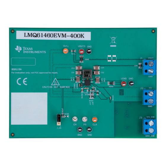
The LMQ61460-Q1 evaluation module (EVM) is designed to help customers evaluate the performance of
the LMQ61460-Q1 synchronous step-down voltage converter. This EVM implements the LMQ61460-Q1 in
a 14-pin wettable flanks Hotrod™ package, as shown in
voltage and up to 6-A load current switching at 400 kHz with exceptional efficiency and output accuracy in
a very small solution size. The EVM provides multiple power connectors and test points. In addition to an
optimized EMI board layout, the LMQ61460-Q1 uses integrated bypass capacitors which results in great
EMI performance.
CONVERTER
U1
SNVU698 – March 2020
Submit Documentation Feedback
LMQ61460EVM-400K User's Guide
Table 1. Device and Package Configurations
IC
LMQ61460-Q1
Figure 1. LMQ61460EVM-400K Top View
Copyright © 2020, Texas Instruments Incorporated
Table
1. It is capable of delivering 5-V output
PACKAGE
14-pin wettable flanks Hotrod package 4.0 mm × 3.5 mm × 1.0 mm
LMQ61460EVM-400K User's Guide
User's Guide
SNVU698 – March 2020
1
Advertisement

Related Manuals for Texas Instruments LMQ61460EVM-400K


Summary of Contents for Texas Instruments LMQ61460EVM-400K
- Page 1 Table 1. Device and Package Configurations CONVERTER PACKAGE LMQ61460-Q1 14-pin wettable flanks Hotrod package 4.0 mm × 3.5 mm × 1.0 mm Figure 1. LMQ61460EVM-400K Top View SNVU698 – March 2020 LMQ61460EVM-400K User's Guide Submit Documentation Feedback Copyright © 2020, Texas Instruments Incorporated...
-
Page 2: Table Of Contents
LMQ61460EVM-400K Board Test Results ......................Bill of Materials Trademarks Hotrod is a trademark of Texas Instruments. All other trademarks are the property of their respective owners. Introduction LMQ61460-Q1 Synchronous Step-Down Voltage Converter The LMQ61460-Q1 is an easy-to-use synchronous step-down DC/DC converter capable of delivering up to 6 A of load current from a supply voltage ranging from 3 V to 36 V. -
Page 3: Introduction
Figure 2. LMQ61460-Q1 Pin Configuration (Top View) LMQ61460-Q1 Evaluation Module The LMQ61460EVM-400K is populated with the LMQ61460AASQRJRRQ1 which automatically reduces frequency at light loads (PFM - pulse frequency modulation). This IC can be replaced with the LMQ61460AFSQRJRRQ1 for a constant switching frequency across load (FPWM - forced pulse width modulation). -
Page 4: Detailed Descriptions
(synonymous with PGOOD pin) of the device is an open-drain output and is pulled up to V through a 100 k resistor. This pin pulls to GND when the output voltage is out of regulation. LMQ61460EVM-400K User's Guide SNVU698 – March 2020 Submit Documentation Feedback Copyright © 2020, Texas Instruments Incorporated... -
Page 5: Schematic
This connector is provided for measuring the input voltage accurately. Schematic The bill of materials is tabulated in Section 7. In addition, Figure 3 shows the corresponding schematic. SNVU698 – March 2020 LMQ61460EVM-400K User's Guide Submit Documentation Feedback Copyright © 2020, Texas Instruments Incorporated... - Page 6 CD1 are placeholders for damping networks to be populated. For more information regarding this topic, reference the EMI Filter Components and Their Nonidealities for Automotive DC/DC Regulators Technical Brief. LMQ61460EVM-400K User's Guide SNVU698 – March 2020 Submit Documentation Feedback Copyright © 2020, Texas Instruments Incorporated...
- Page 7 100 nF (XHMI6060) 2100 kHz 24.9 kΩ 6.04 kΩ 3 x 22 µF 2 x 4.7 µF + 2 x 1 µH (XEL5030) 100 nF SNVU698 – March 2020 LMQ61460EVM-400K User's Guide Submit Documentation Feedback Copyright © 2020, Texas Instruments Incorporated...
-
Page 8: Board Layout
Test points have been provided for ease of use to connect the power supply and required load, and to monitor critical signals. The board measures 3.00" x 4.00" (76mm x 101mm). Figure 4. Top View with Silkscreen LMQ61460EVM-400K User's Guide SNVU698 – March 2020 Submit Documentation Feedback Copyright © 2020, Texas Instruments Incorporated... - Page 9 Board Layout www.ti.com Figure 5. Top Layer Figure 6. Signal Layer 1 - Ground Plane SNVU698 – March 2020 LMQ61460EVM-400K User's Guide Submit Documentation Feedback Copyright © 2020, Texas Instruments Incorporated...
- Page 10 Board Layout www.ti.com Figure 7. Signal Layer 2 - Routing Figure 8. Bottom Layer LMQ61460EVM-400K User's Guide SNVU698 – March 2020 Submit Documentation Feedback Copyright © 2020, Texas Instruments Incorporated...
-
Page 11: Lmq61460Evm-400K Board Test Results
Figure 11. Radiated EMI Measurement with Horizontal Figure 12. Radiated EMI Measurement with Vertical Bicon Bicon Antenna Under CISPR 25 Class 5 Limits Antenna Under CISPR 25 Class 5 Limits SNVU698 – March 2020 LMQ61460EVM-400K User's Guide Submit Documentation Feedback Copyright © 2020, Texas Instruments Incorporated... - Page 12 Figure 13. Radiated EMI Measurement with Horizontal Log Figure 14. Radiated EMI Measurement with Vertical Log Antenna Under CISPR 25 Class 5 Limits Antenna Under CISPR 25 Class 5 Limits LMQ61460EVM-400K User's Guide SNVU698 – March 2020 Submit Documentation Feedback Copyright © 2020, Texas Instruments Incorporated...
-
Page 13: Bill Of Materials
Bill of Materials www.ti.com Bill of Materials The bill of materials is shown Table 3 for the LMQ61460EVM-400K. Table 3. LMQ61460EVM-400K EVM Bill of Materials PACKAGE DESIGNATOR QUANTITY VALUE DESCRIPTION PART NUMBER MANUFACTURER REFERENCE C1, C4 4.7 µF CAP, CERM, 4.7 µF, 50 V, ±20%, X7R, AEC-... - Page 14 Bill of Materials www.ti.com Table 3. LMQ61460EVM-400K EVM Bill of Materials (continued) PACKAGE DESIGNATOR QUANTITY VALUE DESCRIPTION PART NUMBER MANUFACTURER REFERENCE SH-J1 Shunt, 100 mil, Gold plated, Black Shunt 2 pos. 100 mil 881545-2 TE Connectivity TP1, TP9 Test Point, Multipurpose, Red, TH...
- Page 15 TI products. TI’s provision of these resources does not expand or otherwise alter TI’s applicable warranties or warranty disclaimers for TI products. Mailing Address: Texas Instruments, Post Office Box 655303, Dallas, Texas 75265 Copyright © 2020, Texas Instruments Incorporated...
Need help?
Do you have a question about the LMQ61460EVM-400K and is the answer not in the manual?
Questions and answers