Table of Contents
Advertisement
Quick Links
www.ti.com
User's Guide
LMQ61460EVM-400K User's Guide
Sam Jaffe
The LMQ61460-Q1 evaluation module (EVM) is designed to help customers evaluate the performance of the
LMQ61460-Q1 synchronous step-down voltage converter. This EVM implements the LMQ61460-Q1 in a 14-pin
wettable flanks Hotrod
™
6-A load current switching at 400 kHz with exceptional efficiency and output accuracy in a very small solution
size. The EVM provides multiple power connectors and test points. In addition to an optimized EMI board layout,
the LMQ61460-Q1 utilizes integrated bypass capacitors which results in great EMI performance.
CONVERTER
U1
SNVU698B – SEPTEMBER 2020 – REVISED DECEMBER 2020
Submit Document Feedback
package, as shown in
Table
Table 1-1. Device and Package Configurations
IC
LMQ61460-Q1
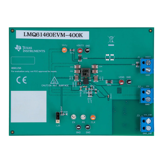
Figure 1-1. LMQ61460EVM-400K Top View
Copyright © 2021 Texas Instruments Incorporated
1-1. It is capable of delivering 5-V output voltage and up to
PACKAGE
14-pin wettable flanks Hotrod package 4.0 mm × 3.5 mm × 1.0 mm
LMQ61460EVM-400K User's Guide
1
Advertisement
Table of Contents

Subscribe to Our Youtube Channel
Related Manuals for Texas Instruments LMQ61460-Q1


Summary of Contents for Texas Instruments LMQ61460-Q1
- Page 1 User’s Guide LMQ61460EVM-400K User's Guide Sam Jaffe The LMQ61460-Q1 evaluation module (EVM) is designed to help customers evaluate the performance of the LMQ61460-Q1 synchronous step-down voltage converter. This EVM implements the LMQ61460-Q1 in a 14-pin wettable flanks Hotrod ™...
-
Page 2: Table Of Contents
Table of Contents www.ti.com Table of Contents Introduction.....................................3 1.1 LMQ61460-Q1 Synchronous Step-Down Voltage Converter.....................3 2 Quick Start Guide..................................4 3 Detailed Descriptions................................Schematic....................................7 4.1 Alternative BOM Configurations............................8 5 Board Layout...................................9 6 LMQ61460EVM-400K Board Test Results...........................12 EMI....................................12 6.2 Board Efficiency................................6.3 Load Regulation................................ -
Page 3: Introduction
3 V to 36 V. The LMQ61460-Q1 provides exceptional efficiency and output accuracy in a very small solution size. The LMQ61460-Q1 is capable of delivering 6 A of load current and implements peak current mode control. The following are additional features that provide both flexible and easy-to-use solutions for a wide range of applications: •... -
Page 4: Quick Start Guide
5 V. 5. Monitor the output voltage with sense points. The maximum load current is 6 A with the LMQ61460-Q1. Note that the maximum output current may need to derate if ambient temperature is high, especially if device is operated at higher frequency, that is 2.1 MHz. -
Page 5: Detailed Descriptions
Input voltage to the converter The V connector connects to the input capacitors and the VIN pins of the LMQ61460-Q1. Connect the supply voltage from a power supply or a battery between VIN and GND connectors as power input to the device. The input voltage (V ) range must be higher than 3.9 V for the device to start up... - Page 6 This connector is provided for measuring the output voltage accurately. VINS VIN sense This connector is provided for measuring the input voltage accurately. LMQ61460EVM-400K User's Guide SNVU698B – SEPTEMBER 2020 – REVISED DECEMBER 2020 Submit Document Feedback Copyright © 2021 Texas Instruments Incorporated...
-
Page 7: Schematic
For more information regarding this topic, reference the EMI Filter Components and Their Nonidealities for Automotive DC/DC Regulators Technical Brief. SNVU698B – SEPTEMBER 2020 – REVISED DECEMBER 2020 LMQ61460EVM-400K User's Guide Submit Document Feedback Copyright © 2021 Texas Instruments Incorporated... -
Page 8: Alternative Bom Configurations
24.9 kΩ 6.04 kΩ 3 x 22 µF 2 x 4.7 µF + 2 x 1 µH (XEL5030) 100 nF LMQ61460EVM-400K User's Guide SNVU698B – SEPTEMBER 2020 – REVISED DECEMBER 2020 Submit Document Feedback Copyright © 2021 Texas Instruments Incorporated... -
Page 9: Board Layout
Board Layout 5 Board Layout Figure 5-1 through Figure 5-5 show the board layout for the LMQ61460-Q1 EVM. The EVM offers resistors, capacitors, and test points to configure the following: • Output voltage (RFBT and RFBB) • Precision enable pin (RENT and RENB) •... - Page 10 Board Layout www.ti.com Figure 5-2. Top Layer Figure 5-3. Signal Layer 1 - Ground Plane LMQ61460EVM-400K User's Guide SNVU698B – SEPTEMBER 2020 – REVISED DECEMBER 2020 Submit Document Feedback Copyright © 2021 Texas Instruments Incorporated...
- Page 11 Board Layout Figure 5-4. Signal Layer 2 - Routing Figure 5-5. Bottom Layer SNVU698B – SEPTEMBER 2020 – REVISED DECEMBER 2020 LMQ61460EVM-400K User's Guide Submit Document Feedback Copyright © 2021 Texas Instruments Incorporated...
-
Page 12: Lmq61460Evm-400K Board Test Results
Figure 6-4. Radiated EMI Measurement with Horizontal Bicon Antenna Under CISPR 25 Class 5 Vertical Bicon Antenna Under CISPR 25 Class 5 Limits Limits LMQ61460EVM-400K User's Guide SNVU698B – SEPTEMBER 2020 – REVISED DECEMBER 2020 Submit Document Feedback Copyright © 2021 Texas Instruments Incorporated... -
Page 13: Board Efficiency
Figure 6-9. F = 400 kHz, 3.3 VOUT, Auto Mode Figure 6-10. F = 400 kHz, 3.3 VOUT, FPWM Mode SNVU698B – SEPTEMBER 2020 – REVISED DECEMBER 2020 LMQ61460EVM-400K User's Guide Submit Document Feedback Copyright © 2021 Texas Instruments Incorporated... -
Page 14: Load Regulation
Figure 6-15. F = 400 kHz, 5 VOUT, Auto Mode Figure 6-16. F = 400 kHz, 5 VOUT, FPWM Mode LMQ61460EVM-400K User's Guide SNVU698B – SEPTEMBER 2020 – REVISED DECEMBER 2020 Submit Document Feedback Copyright © 2021 Texas Instruments Incorporated... -
Page 15: Thermals
A thermal image of the IC was captured to determine rise in temp with a 5-V, 6-A load. The device was soaked for 30 minutes to obtain accurate measurement. SNVU698B – SEPTEMBER 2020 – REVISED DECEMBER 2020 LMQ61460EVM-400K User's Guide Submit Document Feedback Copyright © 2021 Texas Instruments Incorporated... - Page 16 This demonstrates device capability of operating greater than 85°C ambient with headroom. LMQ61460EVM-400K User's Guide SNVU698B – SEPTEMBER 2020 – REVISED DECEMBER 2020 Submit Document Feedback Copyright © 2021 Texas Instruments Incorporated...
-
Page 17: Bill Of Materials
RES, 255 k, 1%, 0.1 W, 0603 0603 RC0603FR-07255KL Yageo SH-J1 Shunt, 100 mil, Gold plated, Black Shunt 2 pos. 100 mil 881545-2 TE Connectivity SNVU698B – SEPTEMBER 2020 – REVISED DECEMBER 2020 LMQ61460EVM-400K User's Guide Submit Document Feedback Copyright © 2021 Texas Instruments Incorporated... - Page 18 RES, 0.51, 1%, 0.25 W, 0805 0805 CRM0805-FX-R510ELF Bourns 100 kΩ RES, 100 k, 1%, 0.1 W, 0603 0603 RC0603FR-07100KL Yageo LMQ61460EVM-400K User's Guide SNVU698B – SEPTEMBER 2020 – REVISED DECEMBER 2020 Submit Document Feedback Copyright © 2021 Texas Instruments Incorporated...
-
Page 19: Revision History
Changed image from 3D imaging to a physical board image................• Added Board Efficiency.............................13 • Added Load Regulation............................ • Added Thermals............................... SNVU698B – SEPTEMBER 2020 – REVISED DECEMBER 2020 LMQ61460EVM-400K User's Guide Submit Document Feedback Copyright © 2021 Texas Instruments Incorporated... - Page 20 STANDARD TERMS FOR EVALUATION MODULES Delivery: TI delivers TI evaluation boards, kits, or modules, including any accompanying demonstration software, components, and/or documentation which may be provided together or separately (collectively, an “EVM” or “EVMs”) to the User (“User”) in accordance with the terms set forth herein.
- Page 21 www.ti.com Regulatory Notices: 3.1 United States 3.1.1 Notice applicable to EVMs not FCC-Approved: FCC NOTICE: This kit is designed to allow product developers to evaluate electronic components, circuitry, or software associated with the kit to determine whether to incorporate such items in a finished product and software developers to write software applications for use with the end product.
- Page 22 www.ti.com Concernant les EVMs avec antennes détachables Conformément à la réglementation d'Industrie Canada, le présent émetteur radio peut fonctionner avec une antenne d'un type et d'un gain maximal (ou inférieur) approuvé pour l'émetteur par Industrie Canada. Dans le but de réduire les risques de brouillage radioélectrique à...
- Page 23 www.ti.com EVM Use Restrictions and Warnings: 4.1 EVMS ARE NOT FOR USE IN FUNCTIONAL SAFETY AND/OR SAFETY CRITICAL EVALUATIONS, INCLUDING BUT NOT LIMITED TO EVALUATIONS OF LIFE SUPPORT APPLICATIONS. 4.2 User must read and apply the user guide and other available documentation provided by TI regarding the EVM prior to handling or using the EVM, including without limitation any warning or restriction notices.
- Page 24 Notwithstanding the foregoing, any judgment may be enforced in any United States or foreign court, and TI may seek injunctive relief in any United States or foreign court. Mailing Address: Texas Instruments, Post Office Box 655303, Dallas, Texas 75265 Copyright © 2019, Texas Instruments Incorporated...
- Page 25 TI products. TI’s provision of these resources does not expand or otherwise alter TI’s applicable warranties or warranty disclaimers for TI products.IMPORTANT NOTICE Mailing Address: Texas Instruments, Post Office Box 655303, Dallas, Texas 75265 Copyright © 2021, Texas Instruments Incorporated...
Need help?
Do you have a question about the LMQ61460-Q1 and is the answer not in the manual?
Questions and answers