Extron electronics SB 33 A Series Setup Manual
Hide thumbs
Also See for SB 33 A Series:
- User manual (51 pages) ,
- Setup manual (15 pages) ,
- User manual (41 pages)
Advertisement
Quick Links
SB 33 A Series • Setup Guide
Product Description
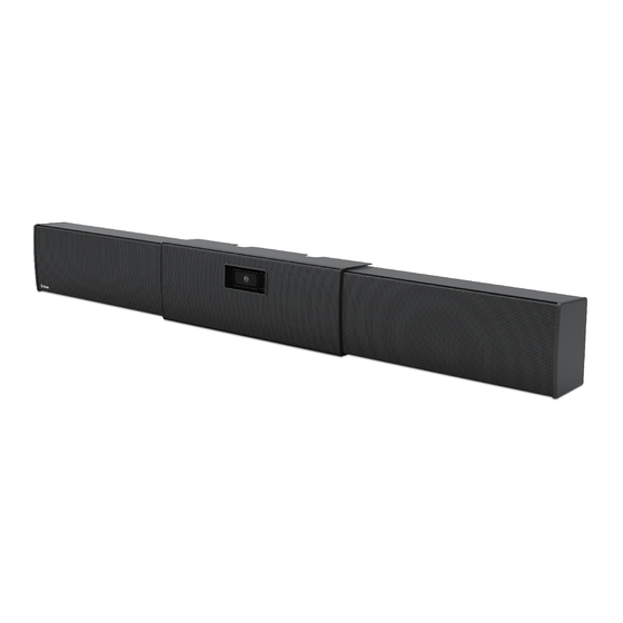
The SB 33 A speaker is an under-the-display powered soundbar speaker for use in small-to-medium conference rooms. It
features two 3" full range speaker drivers driven by an internal amplifier module. The SB 33 A accepts analog and unbalanced
stereo input signals. Three individually buffered inputs are available so three separate sources can be connected without altering
performance.
The SB 33 A speaker enclosure is adjustable to match the width of the display and is mounted under the display. It features
an adjustable shelf to accommodate the mounting of a web cam or small conferencing camera. The SB 33 A is offered in six
different sizes to accommodate screen sizes from 46" to 100" (117 - 254 cm), as shown in the table below.
Option
Fit Display Size (diagonal)
SB 33 A 46-55
SB 33 A 55-65
SB 33 A 65-70
SB 33 A 75-80
SB 33 A 82-90
SB 33 A 90-100
Figure 1.
SB 33 A Series Model Options
46" — 55"
40" — 49" (101.6 cm — 124.5 cm)
55" — 65"
48" — 57" (121.9 cm — 144.8 cm)
65" — 70"
56" — 65" (142.2 cm — 165.1 cm)
75" — 80"
64" — 73" (162.6 cm — 185.4 cm)
82" — 90"
72" — 81" (182.8 cm — 205.7 cm)
90" — 100"
80" — 89" (203.2 cm — 226.1 cm)
40"- 49"
SB 33 A 46-55
48"- 57"
SB 33 A 55-65
56"- 65"
SB 33 A 65-70
64"- 73"
SB 33 A 75-80
72"- 81"
SB 33 A 82-90
80"- 89"
SB 33 A 90-100
Fit Display Width
Speaker Module Width
16.25" (41.3 cm)
20.25" (51.4 cm)
24.25" (61.6 cm)
28.25" (71.8 cm)
32.25" (81.9 cm)
36.25" (92.1 cm)
1
Advertisement

Related Manuals for Extron electronics SB 33 A Series


Summary of Contents for Extron electronics SB 33 A Series
- Page 1 SB 33 A Series • Setup Guide Product Description The SB 33 A speaker is an under-the-display powered soundbar speaker for use in small-to-medium conference rooms. It features two 3" full range speaker drivers driven by an internal amplifier module. The SB 33 A accepts analog and unbalanced stereo input signals.
-
Page 2: Installation Overview
SB 33 A Series • Setup Guide (Continued) Installation Overview The installation of the SB 33 A speaker uses the included wallplate to mark the wall where the SB 33 A is being mounted. After the wallplate is attached to the wall the SB 33 A is then attached to the wallplate. The following section describes the mounting procedure for safely and securely mounting the speaker. - Page 3 Wallplate The wallplate for the SB 33 A 46-55, SB 33 A 55-65, SB 33 A 65-70, and SB 33 A 75-80 models ships as a single piece that is 36.5" long (see figure 4). Figure 4. Wallplate for the SB 33 A 46-55, 55-65, 65-70, and 75-80 Models The wallplate for the SB 33 A 82-90, and SB 33 A 90-100 models ships as two pieces, each 28"...
- Page 4 SB 33 A Series • Setup Guide (Continued) Installing the Wallplate on a Non-masonry Wall Installing the Wallplate on a Masonry Wall NOTE: When attaching the wallplate to masonry, see on page 5. Position and level the included wallplate under the display screen (see figure 8 on page 5).
- Page 5 Wall Stud Wallplate 1/4" SAE Washer (x4) #14 x 1 3/4" Self-tapping Metal or Wood Screws (x4) Figure 8. Attaching the Wallplate to Studs Installing the Wallplate on a Masonry Wall Mount the wallplate on a brick, stone, or concrete wall by doing the following: steps 3 and 4 Follow of “Installing the wallplate on a non-masonry wall”...
- Page 6 SB 33 A Series • Setup Guide (Continued) For each pilot mounting hole: Insert a 1/4" x 1 3/4" masonry screw through a 1/4" SAE washer. Position the wallplate over the pilot holes Insert each screw and washer through the wallplate and into the pilot hole.
- Page 7 Attaching the SB 33 A to the Wallplate ATTENTION: • When attaching either speaker assembly or the center section to the wallplate, avoid damaging or scratching the speaker assembly and center section cover. • Lorsque vous fixez les enceintes ou la section centrale à la plaque murale, prenez garde à ne pas endommager ni à rayer les enceintes et le couvercle de la section centrale.
- Page 8 SB 33 A Series • Setup Guide (Continued) Route the supplied power cable from the power supply in the left speaker enclosure to the power input connector of the amplifier in the right speaker enclosure (see figure 13). REMOTE OUTPUT POWER 0.7A MAX...
- Page 9 NOTE: Speaker and DC power cables must be routed before attaching the center bracket to the wallplate. Hook the top clasp edge of the center bracket over the top rail (figure 15, ) of the wallplate and slide it to center of the display.
- Page 10 SB 33 A Series • Setup Guide (Continued) Attaching Power and Audio Sources to the SB 33 A The SB 33 A has a power supply for the amplifier housed in the left speaker enclosure. The power supply has an AC power input...
- Page 11 Use zip ties to secure cables to the cable tie-off points located on the center bracket, as shown in figure 19. Zip Tie Cable Tie-off Point Front View Figure 19. Securing Cables with Zip Ties Route the audio cable from the display to the audio input connectors of the power amplifier in the right speaker assembly (figure 20, ).
- Page 12 SB 33 A Series • Setup Guide (Continued) Attaching the Center Section Cover Slide the center section cover over the center section and attach the two cover screws to the center bracket standoffs, being careful not to overtighten the screws.
- Page 13 Mounting a Web Camera If mounting a PTZ camera, please go to Mounting a PTZ Camera with Optional PTZ Camera Shelf on page 14. The SB 33 A speaker can accommodate a camera mounted to the center bracket. A small webcam can be mounted behind the center cover, or a larger PTZ camera can be mounted in front of the center cover.
- Page 14 SB 33 A Series • Setup Guide (Continued) Mounting a PTZ Camera with Optional PTZ Camera Shelf A larger PTZ camera that takes up more space can be installed in front of the front cover using the optional PTZ camera shelf.
- Page 15 To install a PTZ camera: PTZ Cables 2 2 2 1 1 1 4 4 4 Zip Tie Cable Tie-off Point 3 3 3 Figure 27. Routing the PTZ Camera Cable Route the PTZ cable to the PTZ camera through the center section cover (figure 27, ) and along a center bracket cable tie-off point ( Secure the cables to the center section tie-off point using a zip tie.
- Page 16 SB 33 A Series • Setup Guide (Continued) Route the cable to the PTZ camera (figure 29, ) and attach it to the camera. Place the camera on the shelf and attach it to the shelf with the mounting screw (...
-
Page 17: Operation
Operation SB 33 A Amplifier Front Panel (inside right speaker) H H H REMOTE Power LED G G G Amplifier power supply connector OUTPUT Captive screw balanced or unbalanced audio input connector F F F RCA unbalanced stereo input connectors INPUTS 3.5 mm unbalanced stereo jack E E E... - Page 18 SB 33 A Series • Setup Guide (Continued) RCA unbalanced stereo input connectors (see figure 31 on the previous page) — These receptacles accept unbalanced, line level audio signals. If unused, the receptacles automatically terminate to lower the noise floor.
- Page 20 For information on safety guidelines, regulatory compliances, EMI/EMF compatibility, accessibility, and related topics, see the Extron Safety and Regulatory Compliance Guide on the Extron website. www.extron.com © 2019-2022 Extron Electronics — All rights reserved. 68-3103-50 Rev. B All trademarks mentioned are the property of their respective owners. 04 22...
Need help?
Do you have a question about the SB 33 A Series and is the answer not in the manual?
Questions and answers