Extron electronics SB 33 A Series User Manual
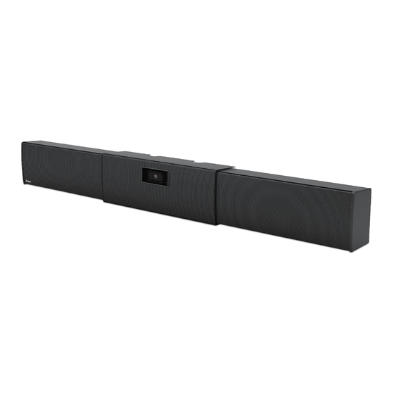
Adjustable width sound bar
Hide thumbs
Also See for SB 33 A Series:
- User manual (51 pages) ,
- Setup manual (20 pages) ,
- Setup manual (15 pages)

Related Manuals for Extron electronics SB 33 A Series


Summary of Contents for Extron electronics SB 33 A Series
- Page 1 User Guide Speakers SB 33 A Series Adjustable Width Sound Bar 68-3103-01 Rev. C 01 22...
- Page 2 Safety Instructions Safety Instructions • English WARNING: This symbol, , when used on the product, is intended to alert the user of the presence of uninsulated dangerous voltage within the product’s enclosure that may present a risk of electric shock. ATTENTION: This symbol, , when used on the product, is intended...
- Page 3 Copyright © 2019-2022 Extron. All rights reserved. www.extron.com Trademarks All trademarks mentioned in this guide are the properties of their respective owners. The following registered trademarks ( ® ), registered service marks ( ), and trademarks ( ) are the property of RGB Systems, Inc. or Extron (see the current list of trademarks on the Terms of Use page at www.extron.com):...
- Page 4 FCC Class B Notice NOTE: This device complies with part 15 of the FCC rules. Operation is subject to the following two conditions: (1) This device may not cause harmful interference, and (2) This device must accept any interference received, including interference that may cause undesired operation.
- Page 5 Conventions Used in this Guide Notifications The following notifications are used in this guide: Potential risk of severe injury or death. WARNING: AVERTISSEMENT : Risque potentiel de blessure grave ou de mort. CAUTION: Risk of minor personal injury. ATTENTION : Risque de blessure mineure.
-
Page 7: Table Of Contents
......30 Defeating the Auto Power-down Timer ....30 Troubleshooting ..........32 Amplifier Fails to Exit Standby Mode Promptly 32 Amplifier Enters Standby Mode Too Early ..33 Extron Warranty ........35 • Contents SB 33 A Series User Guide... - Page 8 • Contents viii SB 33 A Series User Guide...
-
Page 9: Introduction
Introduction This section gives an overview of the Extron SB 33 A Series Sound Bar Speaker. Topics include: • About this Guide • Product Description Features • • Application Example About this Guide This guide describes the installation and set up of the SB 33 A Series Speaker. -
Page 10: Features
Once set, these controls are hidden and protected from tampering • Optional VESA mounting kit • ADA compliant when used with the included wall bracket — Protrudes less than four inches from the wall SB 33 A Series User Guide • Introduction... -
Page 11: Application Example
Application Example The following diagram shows a typical SB 33 A Series installation. 55'' Display Extron SB 33 A 55-65 Sound Bar Analog Audio HDMI/CEC ANT A ANT B HOLD FOR 720p/1080p MENU INPUT AUDIO SIGNAL CONFIG LPCM-2CH Extron HDCP... -
Page 12: Installation
(not included) will secure the SB 33 A speaker wallplate to the wall. SB 33 A Series User Guide • Installation... - Page 13 (17.5 mm) between the highest part of the top rail of the wallplate and the top of the speaker, as shown below. The display screen should not encroach into this area above the top rail. SB 33 A Series User Guide • Introduction...
- Page 14 Drill four pilot holes through the marked locations on the wall. Screw the wallplate to the wall studs using four #14 x 1 3/4” self-tapping wood or metal screws and four 1/4” SAE washers into the pilot holes. SB 33 A Series User Guide • Introduction...
-
Page 15: Installing The Wallplate On A Masonry Wall
Using a masonry drill bit, drill four pilot holes in the masonry wall at the locations you marked in step one. NOTE: If you drill the pilot hole too shallow, the screw head might break off while it is being fastened into the hole. SB 33 A Series User Guide • Introduction... - Page 16 Insert each screw and washer through the wallplate and into the pilot hole. Wallplate 1/4" SAE Washer (x4) 1/4" x 1 3/4" Masonry Screws (x4) Figure 9. Attaching the Wallplate to Masonry Securely tighten the four screws to the wallplate. SB 33 A Series User Guide • Introduction...
-
Page 17: Attaching The Sb 33 A To The Wallplate
Attaching the Right Speaker to the Wallplate Route the supplied power cable from the power supply in the left speaker enclosure to the power input connector of the amplifier in the right speaker enclosure. SB 33 A Series User Guide • Introduction... - Page 18 NOTE: Do not tin the wires. Tinned wire does not hold its shape and can become loose over time. Route the supplied speaker cable from the left speaker module to the left speaker output of the amplifier ( 2 ), as shown in figure 13 on page 11. SB 33 A Series User Guide • Introduction...
-
Page 19: Mounting A Camera
NOTE: If mounting a PTZ Camera, please go to Mounting a PTZ camera with optional PTZ camera shelf on page 13. Both the webcam camera shelf and the PTZ camera shelf use the same two attaching screws and lock washers. SB 33 A Series User Guide • Introduction... - Page 20 A screw is inserted in the bottom slot of the shelf 2 to secure the webcam. Webcam 2 2 2 Screw Figure 16. Securing the Webcam to Shelf To continue the installation, go to Attaching Power and Audio Sources to the SB 33 A on page 15. SB 33 A Series User Guide • Introduction...
- Page 21 Center Bracket Screws (2) PTZ Camera Shelf Lock Washers (2) Figure 18. Attaching the PTZ Camera Shelf To install a PTZ camera, follow the steps below: SB 33 A Series User Guide • Introduction...
- Page 22 Center Section Cover Grille Hook Grille Center Bracket Standoff Screws (2) Figure 20. Attaching the Center Section Cover Attach the grille to the center section cover (see figure 20). SB 33 A Series User Guide • Introduction...
- Page 23 This section describes how the power and audio sources are attached to the SB 33 A, as shown in the following steps. NOTE: Speaker and DC power cables must be routed before attaching the center bracket to the wallplate. See the previous section. SB 33 A Series User Guide • Introduction...
- Page 24 Left Speaker output receptacle (to connectors left speaker) For a detailed description of the above connectors go to the SB 33 A Internal Amplifier Front Panel (Inside Right Speaker Module) on page 25. SB 33 A Series User Guide • Introduction...
- Page 25 Speaker Cable 1 1 1 Figure 27. Routing Speaker Cables from the Display Connect the power cord to the power supply in the left speaker assembly ( 1 ), as shown below. SB 33 A Series User Guide • Introduction...
- Page 26 Attach grille to the center section cover (see figure 29). NOTE: Two grille hooks are included to facilitate grill removal while avoiding damage to the grille. It is best to insert the hook along the outer edge of the grille. SB 33 A Series User Guide • Introduction...
-
Page 27: Smk V Sb 33 Plus Vesa Mounting Kit
SMK V SB 33 Plus VESA Mounting Kit The SMK V SB 33 Plus VESA Mounting Kit allows the SB 33 A Series of soundbar speakers to be attached to the same VESA display mount supporting the display device. This type of installation enables the SB 33 speaker to be aligned with the display for a visually aesthetic installation. - Page 28 If the bracket is exposed over the top of the display, the top 8″ of the SMK V SB 33 Plus long L-braclet can be broken off. To do this, simply bend the top breakaway portion back at the seam until it breaks off. SB 33 A Series User Guide • Installation...
- Page 29 Hand tighten all 4 bolts. Spacers are provided if needed (see figure 31 to see where the spacers go). VESA Display Mount (not included) Mounting Screws Washers Long L-brackets Figure 32. Installing VESA Display Mount to Long L-brackets SB 33 A Series User Guide • Installation...
- Page 30 Tighten the bolts and permanently fasten the display onto the VESA wall mount previously attached. To adjust the SB 33 speaker vertically: Loosen, but do not remove, the bolts that attach the long L-brackets to the display. SB 33 A Series User Guide • Installation...
- Page 31 Depending on the short • L-bracket orientation and depth adjustment —It is possible to adjust the SB 33 speaker height by adjusting the wall bracket position on the short L-bracket. SB 33 A Series User Guide • Installation...
- Page 32 Loosen, but do not remove, the two wingnuts attaching the long L-brackets to the short L-brackets. Adjust the soundbar speaker to either the front or the rear of the display and then tighten the wingnuts. Long L-bracket Short L-bracket Depth Adjustment Figure 37. Adjusting Depth SB 33 A Series User Guide • Installation...
-
Page 33: Operation
3.5 mm captive screw outlets on the power supply. Connect the other end into the power receptacle on the rear panel of the amplifier (see figure 40 page 27). The power cord connectors are correctly wired when shipped. SB 33 A Series User Guide • Operation... - Page 34 Remote volume control connector — This 3-pin, captive screw port allows an audio controller to control volume and mute levels remotely (see Wiring for Remote Control on page 27). V C G 50mA SB 33 A Series User Guide • Operation...
- Page 35 Mute — It can be used for remote control muting. Sound is muted while this pin is • shorted to ground. • Pin 3 is for the ground connection. NOTE: All nominal levels are at ±10%. SB 33 A Series User Guide • Operation...
-
Page 36: Internal Adjustments
Slowly increase the amplifier level by rotating the LEVEL potentiometer clockwise until sound distortion starts. Lower the level slightly until the distortion disappears. At this setting, whatever the volume setting of the audio source, no clipping should occur. SB 33 A Series User Guide • Operation... -
Page 37: Setting Bass And Treble
NOTE: Turning the BASS or TREBLE potentiometers counterclockwise will decrease the output at the specified frequencies. Turning the potentiometers clockwise will increase the output. When the potentiometer is in the center, flat response is achieved. SB 33 A Series User Guide • Operation... -
Page 38: Reference Information
(see figure 29 on page 18). Disconnect the power cable from the amplifier. Disconnect all audio cables that attach to the amplifier. Disconnect any connections to the remote input connector. SB 33 A Series User Guide • Reference... - Page 39 Soyez prudent en retirant les vis afin d’éviter d’abîmer les têtes de vis. Slide the cover forward a little then lift the cover straight up and place it out of the way. The circuit boards are now exposed at the back. SB 33 A Series User Guide • Reference...
-
Page 40: Troubleshooting
No output signal. Check the Remote port. Green or Amber The input signal may be too weak. Slow to exit standby mode when a signal is present. Raise the level of the source signal. SB 33 A Series User Guide • Reference... -
Page 41: Amplifier Enters Standby Mode Too Early
Amplifier Enters Standby Mode Too Early Power LED Color Problem Description Problem Solution Green or Amber Enters standby mode early. The input signal may be too weak. Raise the level of the source signal. SB 33 A Series User Guide • Reference... - Page 42 SB 33 A Series User Guide • Reference...
-
Page 43: Extron Warranty
Extron Electronics makes no further warranties either expressed or implied with respect to the product and its quality, performance, merchantability, or fitness for any particular use. In no event will Extron Electronics be liable for direct, indirect, or consequential damages resulting from any defect in this product even if Extron Electronics has been advised of such damage. - Page 44 Worldwide Headquarters: Extron USA West, 1025 E. Ball Road, Anaheim, CA 92805, 800.633.9876...
Need help?
Do you have a question about the SB 33 A Series and is the answer not in the manual?
Questions and answers