Extron electronics SB 33 A Series Setup Manual
Hide thumbs
Also See for SB 33 A Series:
- User manual (51 pages) ,
- Setup manual (20 pages) ,
- User manual (44 pages)
Table of Contents
Advertisement
Quick Links
Download this manual
See also:
User Manual
SB 33 A Series • Setup Guide
Product Description
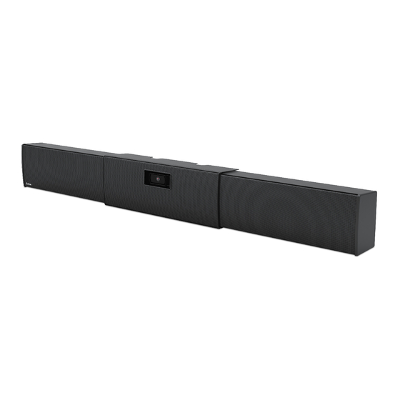
The SB 33 A speaker is an under-the-display powered soundbar speaker for use in small-to-medium conference rooms. It
features two 3" full range speaker drivers driven by an internal amplifier module. The SB 33 A accepts analog and unbalanced
stereo input signals. Three individually buffered inputs are available so three separate sources can be connected without altering
performance.
The SB 33 A speaker enclosure is adjustable to match the width of the display and is mounted under the display. It features
an adjustable shelf to accommodate the mounting of a web cam or small conferencing camera. The SB 33 A is offered in four
different sizes to accommodate screen sizes from 46" to 80", as shown in the table below.
Installation Overview
The installation of the SB 33 A speaker uses the included wallplate to mark the wall where the SB 33 A is being mounted. After
the wallplate is attached to the wall the SB 33 A is then attached to the wallplate. The following section describes the mounting
procedure for safely and securely mounting the speaker.
NOTE:
Install the wallplate onto wall material using common installation methods with applicable hardware dictated per
local building code.
Option
Fit Display Size (diagonal)
SB 33 A 46-55
SB 33 A 55-65
SB 33 A 65-70
SB 33 A 75-80
46" — 55"
40" — 49" (101.6 cm — 124.5 cm)
55" — 65"
48" — 57" (121.9 cm — 144.8 cm)
65" — 70"
56" — 65" (142.2 cm — 165.1 cm)
75" — 80"
64" — 73" (162.6 cm — 185.4 cm)
40"- 49"
SB 33 A 46-55
48"- 57"
SB 33 A 55-65
56"- 65"
SB 33 A 65-70
64"- 73"
SB 33 A 75-80
Fit Display Width
Speaker Module Width
16.25" (41.3 cm)
20.25" (51.4 cm)
24.25" (61.6 cm)
28.25" (71.8 cm)
1
Advertisement
Table of Contents

Related Manuals for Extron electronics SB 33 A Series


Summary of Contents for Extron electronics SB 33 A Series
-
Page 1: Product Description
SB 33 A Series • Setup Guide Product Description The SB 33 A speaker is an under-the-display powered soundbar speaker for use in small-to-medium conference rooms. It features two 3" full range speaker drivers driven by an internal amplifier module. The SB 33 A accepts analog and unbalanced stereo input signals. -
Page 2: Preparing The Mounting Location
SB 33 A Series • Setup Guide (Continued) Preparing the Mounting Location Display Left Speaker Module Center Right Speaker Module Bracket NOTE: Observe all applicable building codes and local ordinances when installing the SB 33 A speaker. Before starting the installation, remove the center section assembly from the packaging and do the following:... - Page 3 NOTE: Assuming that the display screen is level, allow for some space between the bottom of the display screen and the top of the speaker because the speaker assemblies and the center bracket attach to the wallplate by hooking the top mounting clasps of the speaker assemblies and center bracket over the top mounting rail of the wall plate.
- Page 4 SB 33 A Series • Setup Guide (Continued) Installing the Wallplate on a Masonry Wall Mount the wallplate on a brick, stone, or concrete wall by doing the following: Follow steps 1 and 2 of “Installing the wallplate on a non-masonry wall” starting on page 2.
- Page 5 Attaching the SB 33 A to the Wallplate ATTENTION: • When attaching either speaker assembly or the center section to the wallplate, avoid damaging or scratching the speaker assembly and center section cover. • Lorsque vous fixez les enceintes ou la section centrale à la plaque murale, prenez garde à ne pas endommager ni à...
- Page 6 SB 33 A Series • Setup Guide (Continued) ATTENTION: • Always use a power supply supplied by or specified by Extron. Use of an unauthorized power supply voids all regulatory compliance certification and may cause damage to the supply and the end product.
-
Page 7: Front View
Attaching Power and Audio Sources to the SB 33 A The SB 33 A has a power supply for the amplifier housed in the left speaker enclosure. The power supply has an AC power input connector ( ) and a DC power output connector ( ) that routes power to the amplifier. - Page 8 SB 33 A Series • Setup Guide (Continued) Cables can be be secured with zip ties to cable tie off points located on the center bracket, as shown below. Zip Tie Cable Tie-off Point Front View Route the audio cable from the display to the audio input connectors of the power amplifier ( ) in the right speaker assembly.
- Page 9 Attaching the Center Section Cover Slide the center section cover over the center section and attach the two cover screws to the center bracket standoffs being careful not to overtighten the screws. Center Bracket Center Section Cover Grille Screws (2) Attach the grille to the center section cover.
- Page 10 SB 33 A Series • Setup Guide (Continued) A screw is inserted in the bottom slot of the shelf ( ) to secure the webcam. Webcam Screw Option 2 Attaching the Center Section Cover on page 9 to continue the installation.
- Page 11 Center Bracket Screws (2) PTZ Camera Shelf Lock Washers (2) To install a PTZ camera: PTZ Cables Zip Tie Cable Tie-off Point Route the PTZ cable to the PTZ camera through the center section cover ( ) and along a center bracket cable tie- off point ( Route the cable to the camera shelf ( Route the cable through the access hole at the rear of the camera shelf (...
- Page 12 SB 33 A Series • Setup Guide (Continued) Center Section Cover Grille Hook Grille Center Bracket Standoff Screws (2) Attach the grille to the center section cover. See the illustration above. NOTE: Two grille hooks are included to facilitate grille removal while avoiding damage to the grille. It is best to insert the hook along the top or bottom outer edge of the grille, as shown above.
-
Page 13: Operation
Center Section Webcam Doors and Door Rails Center Section Cover Grille Screws (4) Remove the center section webcam doors and door rails (not shown). Attach the blank grille to the center section cover. Operation SB 33 A Amplifier Front Panel (inside right speaker) REMOTE Power LED OUTPUT... - Page 14 SB 33 A Series • Setup Guide (Continued) REMOTE OUTPUT POWER 0.7A MAX INPUTS DC Power DC Power Outputs Input Left Speaker Module DC Power Cord Right Speaker Module Captive Screw Power Supply Amplifier Connectors Wraps Captive screw balanced or unbalanced audio input connector — This 5-pole 3.5 mm captive screw receptacle accepts line level, balanced or unbalanced, mono or stereo audio signals.
- Page 15 For information on safety guidelines, regulatory compliances, EMI/EMF compatibility, accessibility, and related topics, see the Extron Safety and Regulatory Compliance Guide on the Extron website. www.extron.com © 2019 Extron Electronics — All rights reserved. 68-3103-50 Rev. A All trademarks mentioned are the property of their respective owners. 02 19...
Need help?
Do you have a question about the SB 33 A Series and is the answer not in the manual?
Questions and answers