Table of Contents
Advertisement
Quick Links
Advertisement
Table of Contents

Summary of Contents for Motorline professional MC112PR
- Page 1 MC112PR | MC113PR | MC114PR USER’S AND INSTALLER’S MANUAL V3.0 REV. 08/2022...
-
Page 2: Table Of Contents
00.CONTENT 01. SAFETY INSTRUCTIONS INDEX ATTENTION: 01. SAFETY INSTRUCTIONS This product is certified in accordance with European Community (EC) safety standards. 02. PRODUCT DESCRIPTION OF PRODUCT This product complies with Directive 2011/65/EU of the TECHNICAL CHARACTERISTICS DIMENSIONS European Parliament and of the Council, of 8 June 2011, on COMPONENTS MAP the restriction of the use of certain hazardous substances in electrical and electronic equipment. - Page 3 01. SAFETY INSTRUCTIONS GENERAL WARNINGS the motorized door or gate from being triggered involuntarily. • This manual contains very important safety and usage information. WARNINGS FOR TECHNICIANS very important. Read all instructions carefully before beginning the installation/usage procedures and keep this manual in a safe place •...
- Page 4 01. SAFETY INSTRUCTIONS to the release mechanism. • Disconnect means, such as a switch or circuit breaker on the electrical RESPONSABILITY panel, must be provided on the product’s fixed power supply leads in • Supplier disclaims any liability if: accordance with the installation rules. •...
-
Page 5: Product
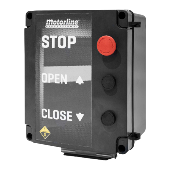
• This control board is also capable of receiving a ROLLING CODE remote controls signal (MR13 receiver) 8 · Opening button and allows the connection of MF2020 Photocells. 9 · Closing button 10 · MF2020 column photocell TECHNICAL CHARACTERISTICS MC112PR MC113PR MC114PR • Power 750W max 750W to 1500W 1500W to 2200W •... -
Page 6: Components
03. COMPONENTS 03. COMPONENTS MR13 - RECEIVER MF2020 The MF2020 is a column photocell designed to safeguard all types of industrial doors (sectional and rapid LEARN BUTTON doors) up to a maximum width of 10 meters. The emitter and receiver create a grid of infrared beams offering protection up to 2.5 meters high (depending •... -
Page 7: Inverters And Conectors
04. INVERTERS AND CONECTORS FREQUENCY INVERTERS MC112PR (Up to 750W) MC113PR (750W to 1500W) MC114PR (1500W to 2200W) 16 13 14 15 17 14 15 16 13 14 15 17 14 15 16 13 14 15 17 14 15 8 20... -
Page 8: Frequency Inverters Connections 7A
04. INVERTERS AND CONECTORS 04. INVERTERS AND CONECTORS FREQUENCY INVERTERS CONNECTIONS CONNECTIONS CONNECTORS The following panel are all inputs and The below panel ate all inputs and outputs of connection connectors. 24V • Common STOP outputs of frequency inverter. S1 • STOP button S2 •... -
Page 9: Connections Squeme
05. CONNECTIONS SQUEME FREQUENCY INVERTER CONNECTIONS Brown Blue SGND FREQUENCY VARIATOR... -
Page 10: Mr13 Receiver Connections
05. CONNECTIONS SQUEME MR13 RECEIVER CONNECTIONS MR13 Brown Blue SGND FREQUENCY VARIATOR... -
Page 11: Other Connections (Magnetic Loop Detector, Resistor And Push Button)
05. CONNECTIONS SQUEME OTHER CONNECTIONS (MAGNETIC LOOP DETECTOR, RESISTOR AND PUSH BUTTON) LOOP1 • LOOP1 for Magnetic Loop LOOP1 • LOOP1 for Magnetic Loop LOOP2 • LOOP2 for Magnetic Loop LOOP2 • LOOP2 for Magnetic Loop Brown MAGNETIC LOOP DETECTOR Blue RESISTOR SGND... -
Page 12: Closing Pre- Flashing Light
05. CONNECTIONS SQUEME CLOSING PRE- FLASHING LIGHT NO • 24Vdc 3W Negative Output COM • Common SGND FREQUENCY INVERTER... -
Page 13: Ups Unit Connection
05. CONNECTIONS SQUEME UPS UNIT CONNECTION UPS POWER SUPPLY OUTPUT UPS POWER SUPPLY INPUT UPS UNIT COM • Common NC • Relay Contact A1 • Power Supply A2 • Power Supply N (OUT) • Power Supply L (OUT) • Power Supply N (IN) •... -
Page 14: Relay For Two-Door Interlock
05. CONNECTIONS SQUEME RELAY FOR TWO-DOOR INTERLOCK COM • Common NC • Relay Contact When using relay for two-door interlock, it is A • Connector necessary to change the connection indicated for B • Connector this wire on page 9, to the one indicated here. FREQUENCY INVERTER SGND... -
Page 15: External Components Connections
05. CONNECTIONS SQUEME EXTERNAL COMPONENTS CONNECTIONS Blue Black Green Yellow CLOSING OPENING... -
Page 16: Descriptions
06. DESCRIPTIONS 06. DESCRIPTIONS DIGITAL NUMERIC KEYBOARD MENU NAVIGATION Press ENTER to enter the MENU Using the arrows, select one of the SUBMENUS referenced on page 16A. OK Inverter UP movement Press ENTER to enter the SUBMENU. DOWN movement Status Display Shows the current state of the STOP Stand By... -
Page 17: Lock/Unlock Keyboard 16A
06. DESCRIPTIONS 06. DESCRIPTIONS LOCK/UNLOCK KEYBOARD PROGRAMMING MENU ACCESS (MENU 04) Keyboard locking is done through a password. Below are the steps for configuring and using the password. SET PASSWORD Enter at parameter 00.08 and set password to lock the Press MODE until you find H function. -
Page 18: Programming Menu
06. DESCRIPTIONS 06. DESCRIPTIONS PROGRAMMING MENU - 04 PROGRAMMING MENU - 04 Parameter Function Settings Factory Setting If the values are incorrectly adjusted, there is a risk of damage to the motor and inverter. PEDESTRIAN OPENING TIME This menu can select the length of the pedestrian opening. Knowing 04.57 that 100 means 8M if put 12 means opening of a meter. -
Page 19: Programming
07. PROGRAMMING SLOWDOWN ADJUSTMENT Slowdown is a reduction in the door's movement speed until it reaches the limit switch. To adjust the slowdown at opening and closing the door, follow these steps in the following order: Ensure that the limit switches are adjusted to the movement of the door. - Page 20 07. PROGRAMMING 08. TROUBLESHOOTING LED DISPLAY MESSAGES INSTRUCTIONS FOR CONSUMERS AND SPECIALIZED TECHNICIANS Message Fault identifi- Description Description of failure Corrections displayed cation Displays the master frequency of the AC inverter. 01 • Check if the motor power corresponds to the output power of the AC motor inverter.


Need help?
Do you have a question about the MC112PR and is the answer not in the manual?
Questions and answers