
Related Manuals for Motorline professional MC102


Summary of Contents for Motorline professional MC102
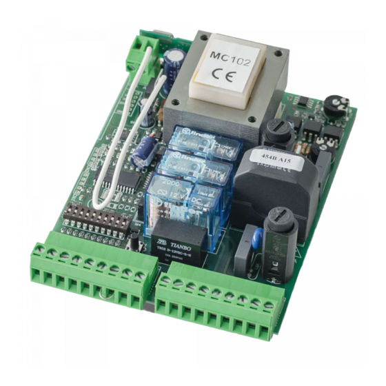
- Page 1 CONTROL BOARD MC102 USER / INSTALLER MANUAL v1.0 REV. 10/2013...
- Page 2 CONTENT SAFETY INSTRUCTIONS íNDEX STANDARDS TO FOLLOW 00. CONTENT ATTENTION: índex | page 01.A To ensure the safety of people, it is important that you read all the following 01. SAFETY INSTRUCTIONS instructions.Incorrect installation or incorrect use of the product can cause physical standards to follow | page 01.B injury and material damage.
- Page 3 THE CONTROL BOARD THE CONTROL BOARD TECHNICAL SPECIFICATIONS PROGRAMMING PRE-RECOMMENDATIONS Before proceeding to the control board configuration, note the following points listed Power supply AC 230V 50/60Hz in the table below in order to better understand the control board function: Lightbulb’s output AC230V 40W máx.
- Page 4 DIPPERS DIPPERS DIPPERS FUNCTION’S BOARD DIPPERS FUNCTION’S BOARD Dip 4 OFF | Dip 5 ON Dip 4 ON | Dip 5 OFF Normal Step-by-step function Condominium function with Dip 4 without automatic closure. automatic locking: NOTE: The control board in standard mode has all the dippers in OFF mode. Gate opens or closes only if it Transmitters aren’t accepted during Dip 5...
- Page 5 CONFIGURATION CONFIGURATION INSTALLATION PROCESS INSTALLATION PROCESS Total Opening and transmitter programming: Button 1 Button 3 Button 1 Place all the dippers in OFF position Button 2 Button 4 Button 4 Button 2 (down). In case of not using safety device Button 3 Mola do at 4/M2 terminal (ex:photocells), place...
- Page 6 CONFIGURATINON COMPONENT TEST INSTALLATION PROCESS CAPACITATOR SCHEME If the control board blocks and a RESET is needed, follow these steps: To detect which components have problems during an sliding automatism installation, Turn o the control board’s power. sometimes is necessary to conduct tests with a direct connection to a 230V power Put Dipper 9 to ON.
- Page 7 TROUBLESHOOTING FINAL CONSUMERS INSTRUCTIONS SPECIALIZED TECHNICIANS INSTRUCTIONS Anomaly Procedure Behavior Procedure II Discovering the origin of the problem Door Make sure you Still not Consult a qualified Open control board and check Disconnect the motor from If the motor works, the 5 If the motor doesn’t work, doesn't work have 230V power...
- Page 8 WIRING DIAGRAM CONTROL BOARD COMPONENT CONNECTION 07.A...
Need help?
Do you have a question about the MC102 and is the answer not in the manual?
Questions and answers