Table of Contents
Advertisement
Quick Links
Advertisement
Table of Contents

Related Manuals for Metrohm OMNIS Titrator


Summary of Contents for Metrohm OMNIS Titrator
- Page 1 OMNIS Titrator 2.1001.0X20 Product manual 8.1001.8002EN / 2021-09-23...
- Page 3 Metrohm AG Ionenstrasse CH-9100 Herisau Switzerland +41 71 353 85 85 info@metrohm.com www.metrohm.com OMNIS Titrator 2.1001.0X20 Product manual 8.1001.8002EN / 2021-09-23...
- Page 4 Disclaimer Deficiencies arising from circumstances that are not the responsibility of Metrohm, such as improper storage or improper use, etc., are expressly excluded from the warranty. Unauthorized modifications to the product (e.g. conversions or attachments) exclude any liability on the part of the manufacturer for resulting damage and its consequences.
-
Page 5: Table Of Contents
■■■■■■■■■■■■■■■■■■■■■■ Table of contents Table of contents 1 Overview OMNIS Titrator – Product description ........ 1 OMNIS Titrator – Product versions ........1 Symbols and conventions ............ 2 Further information .............. 2 Accessories ................3 2 Safety Intended use ................. 4 Responsibility of the operator .......... - Page 6 Volumetric Karl Fischer titration cell – Function ...... 29 OMNIS main instrument – Indicators and controls ..30 System – Signals ..............31 OMNIS Titrator – Interfaces ..........32 Measuring Module Analog – Interfaces ......33 Measuring Module Digital – Interfaces ......34 4 Delivery and packaging Delivery ................
- Page 7 10 Disposal 11 Technical specifications 11.1 Ambient conditions ............85 11.2 OMNIS Titrator – Energy supply ........85 11.3 Magnetic stirrer – Energy supply ........85 11.4 Measuring module – Energy supply ........86 11.5 OMNIS Titrator – Dimensions ..........86 11.6 Magnetic stirrer –...
- Page 8 Table of contents ■■■■■■■■■■■■■■■■■■■■■■ 11.21 OMNIS Titrator – Liquid Handling specifications .... 94 11.22 Magnetic stirrer – Specifications ........94 ■■■■■■■■ OMNIS Titrator...
-
Page 9: Overview
OMNIS Titrator – Product description The OMNIS Titrator is the central instrument of an OMNIS titration system. The OMNIS Titrator is responsible for the energy supply to all of the mod- ules in the titration system and for communication between the titration system and the OMNIS Software. -
Page 10: Symbols And Conventions
Symbols and conventions ■■■■■■■■■■■■■■■■■■■■■■ (01) = Article number in accordance (21) = Serial number with GS1 standard (240) = Metrohm article number Certification Certification Technical specifications Symbols and conventions The following formatting may appear in the documentation: Cross-reference to figure legend The first number refers to the figure number. -
Page 11: Accessories
■■■■■■■■■■■■■■■■■■■■■■ Overview Accessories Up-to-date information on the scope of delivery and on optional accesso- ries can be found on the Metrohm website. Download this information as follows: Downloading the accessories list 1 Go to https://www.metrohm.com. 2 Enter the article number of the product (e.g. 2.1001.0010) into the search field. -
Page 12: Safety
■■■■■■■■■■■■■■■■■■■■■■ 2 Safety Intended use Metrohm products are used for the analysis and handling of chemicals. Usage therefore requires the user to have basic knowledge and experience in handling chemicals. Knowledge regarding the application of fire preven- tion measures prescribed for laboratories is also mandatory. -
Page 13: Requirements For Operating Personnel
Always have maintenance work and repairs on electrical components ■ carried out by a regional Metrohm service representative. Disconnect the product from the energy supply immediately if at least ■ one of the following cases occurs: –... -
Page 14: Danger From Highly Flammable Substances
Dispose of chemically contaminated materials (e.g. cleaning material) in ■ accordance with regulations. Proceed as follows in case of a return shipment to Metrohm AG or a ■ regional Metrohm representative: – Decontaminate the product or product component. -
Page 15: Danger During Transport Of The Product
■■■■■■■■■■■■■■■■■■■■■■ Safety 2.4.5 Danger during transport of the product Chemical or biological substances may be spilled during the transport of the product. Parts of the product may fall down or may be damaged. There is a risk of injury from chemical or biological substances and pieces of broken glass. -
Page 16: Meaning Of Warning Signs
Meaning of warning signs ■■■■■■■■■■■■■■■■■■■■■■ Meaning of warning signs This documentation uses the following warning signs: Table 2 Warning sign according to ISO 7010 Warning sign Meaning General warning sign Warning of electrical voltage Warning of hand injuries Warning of sharp object Warning of hot surface Warning of biological hazard Warning of toxic materials... -
Page 17: Functional Description
■■■■■■■■■■■■■■■■■■■■■■ Functional description 3 Functional description Single-workplace titration system – Overview Figure 1 Single-workplace titration system – Front FEP tubing Cylinder unit Measuring module Electrode cable Electrode Antidiffusion tip Support rod Electrode holder Clamping ring 10 Stirring bar 11 Sample beaker ■■■■■■■■... - Page 18 Single-workplace titration system – Overview ■■■■■■■■■■■■■■■■■■■■■■ Figure 2 Single-workplace titration system – Rear OMNIS Liquid Adapter Bottle cap multi-use Chemical bottle Bottle holder ■■■■■■■■...
-
Page 19: Single-Workplace Titration System For Volumetric Karl Fischer Titrations - Overview
Figure 3 Single-workplace titration system for volumetric Karl Fischer titrations Measuring Module Analog Cylinder unit installed Metrohm recommends 10 mL cylinder units for Karl Fischer titrations. Chemical bottle (titrant) Karl Fischer titration cell (volumetric) with OMNIS Liquid Adapter Support rod... -
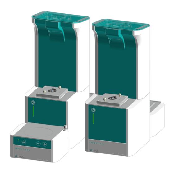
Page 20: Omnis Titrator - Overview
OMNIS Titrator – Overview ■■■■■■■■■■■■■■■■■■■■■■ OMNIS Titrator – Overview Figure 4 OMNIS Titrator – Front Space for measuring modules Dosing drive Magnetic stirrer Platform For chemical bottles ■■■■■■■■... - Page 21 OMNIS Titrator – Rear Bottle holder Cable guide On the side to the right. For Liquid Adapter cable MSI connector Cable guide MSI = Metrohm Solution Identification. Con- Bottom right nection socket for Liquid Adapter cable Interfaces Cable guide Bottom left Cable guide On the side to the left.
-
Page 22: Magnetic Stirrer - Overview
OMNIS Titrator – Overview ■■■■■■■■■■■■■■■■■■■■■■ 3.3.1 Magnetic stirrer – Overview Figure 6 Magnetic stirrer – Overview Stand attachment Stirring area Control bar Status display LED. Multi-colored ■■■■■■■■... -
Page 23: Magnetic Stirrer With Accessories - Overview
Support rod Electrode holder Clamping ring Control bar The support rod is grounded. The OMNIS Titrator and OMNIS Titra- tion Module have a hole in the support rod that serves as earth con- tact for a banana plug (4 mm). ■■■■■■■■... -
Page 24: Dosing Unit - Overview
OMNIS Titrator – Overview ■■■■■■■■■■■■■■■■■■■■■■ 3.3.3 Dosing unit – Overview Figure 8 Dosing unit – Overview Cylinder unit Dosing drive Available with various volumes Not in scope of delivery ■■■■■■■■... - Page 25 ■■■■■■■■■■■■■■■■■■■■■■ Functional description Figure 9 Dosing drive – Overview Status display Contact pins LED. Multi-colored For communicating with the cylinder unit Twistlocks Piston rod For locking the cylinder unit For moving the dosing piston Valve coupling ■■■■■■■■...
- Page 26 OMNIS Titrator – Overview ■■■■■■■■■■■■■■■■■■■■■■ 3.3.3.1 Cylinder unit OMNIS – Overview Figure 10 Cylinder unit – Overview Distributor with 4 ports Cylinder top piece Cylinder housing Centering tube Cylinder Data chip Piston stopper Dosing piston Spring clip 10 Unlocking button...
- Page 27 ■■■■■■■■■■■■■■■■■■■■■■ Functional description Figure 11 Cylinder unit – Overview from above The following table shows the standard use of the 4 ports. The use of the ports can be changed in the OMNIS Software. Port Connecting or sealing with Dosing Dosing tip Filling the cylinder Chemical bottle...
-
Page 28: Bottle Unit - Overview
OMNIS Titrator – Overview ■■■■■■■■■■■■■■■■■■■■■■ 3.3.4 Bottle unit – Overview Figure 12 Bottle unit OMNIS Liquid Adapter Bottle cap multi-use Chemical bottle ■■■■■■■■... - Page 29 ■■■■■■■■■■■■■■■■■■■■■■ Functional description 3.3.4.1 OMNIS Liquid Adapter – Overview Figure 13 OMNIS Liquid Adapter – Parts Cable Status display RFID reader Aspiration tube Part of 6.01600.xxx Tubing adapter Part of 6.01600.xxx ■■■■■■■■...
- Page 30 OMNIS Titrator – Overview ■■■■■■■■■■■■■■■■■■■■■■ 3.3.4.2 Bottle cap multi-use – Overview Figure 14 Bottle cap multi-use, complete (6.01601.000) Flip-top lid Aspiration tubing Aspiration tubing (6.1819.020) RFID tag PTFE sealing ring RFID chip for contact-free data transmission. PTFE sealing ring (6.02701.010)
-
Page 31: Measuring Module Analog - Overview
■■■■■■■■■■■■■■■■■■■■■■ Functional description 3.3.5 Measuring Module Analog – Overview Figure 15 Measuring Module Analog – Overview INPUT 1 INPUT 2 Connection socket for potentiometric sen- Connection socket for potentiometric sen- sors (green coding), temperature sensors sors (green coding) and temperature sensors (red coding) and polarizable sensors (blue (red coding) coding) -
Page 32: Measuring Module Digital - Overview
OMNIS Titrator – Overview ■■■■■■■■■■■■■■■■■■■■■■ 3.3.6 Measuring Module Digital – Overview Figure 16 Measuring Module Digital – Overview Fastening screws Connection socket Fastening screws, left and right. These fasten For dTrodes the measuring module in the housing and ground the electronics. -
Page 33: Measuring Module Conductivity - Overview
■■■■■■■■■■■■■■■■■■■■■■ Functional description 3.3.7 Measuring Module Conductivity – Overview Figure 17 Measuring Module Conductivity – Overview Fastening screws Measuring input For conductivity measuring cell (see Measur- ing Module Conductivity – Connector speci- fications, page Status display LED (green-red) Various conductivity measuring cells with integrated temperature sensor can be connected to the measuring input of the Measuring Module Con- ductivity, see Electrode... -
Page 34: Volumetric Karl Fischer Titration Cell - Overview
OMNIS Titrator – Overview ■■■■■■■■■■■■■■■■■■■■■■ 3.3.8 Volumetric Karl Fischer titration cell – Overview Figure 18 Installed volumetric Karl Fischer titration cell – Overview Support rod Locking lever Titration vessel lid Clamping ring Titration vessel Control bar for magnetic stirrer ■■■■■■■■... -
Page 35: Omnis Titrator - Function
The OMNIS Titrator with magnetic stirrer can also be used as a stand- alone instrument with manual sample change. -
Page 36: Bottle Unit - Function
OMNIS Titrator – Function ■■■■■■■■■■■■■■■■■■■■■■ If the cylinder unit is placed on top of the dosing drive, the dosing drive assumes responsibility for the following functions: Raising and lowering the dosing piston: ■ Solution is aspirated if the dosing piston is lowered. The cylinder fills Solution is dosed if the dosing piston is raised. -
Page 37: Measuring Module Analog - Functional Description
3.4.5 Measuring Module Digital – Functional description The Measuring Module Digital is used as an interface for digital electrodes on an OMNIS Titrator or an OMNIS Titration Module. The digital electrodes, the dTrodes, can be plugged into its connection socket. -
Page 38: Omnis Main Instrument - Indicators And Controls
OMNIS main instrument – Indicators and controls ■■■■■■■■■■■■■■■■■■■■■■ OMNIS main instrument – Indicators and controls Figure 19 OMNIS main instrument – Indicators and controls On/off switch Status display Multi-colored Indicators The status of the main instrument is displayed with the status display using different colors (19-2) (see "System –... -
Page 39: System - Signals
■■■■■■■■■■■■■■■■■■■■■■ Functional description System – Signals System components with status indicators show their operating status with colors and/or flashing patterns. The meaning of the colors and flash- ing patterns is explained in the following table. Visual signal Meaning LED lights up yellow. System start or initialization LED flashes yellow (slowly). -
Page 40: Omnis Titrator - Interfaces
OMNIS Titrator – Interfaces ■■■■■■■■■■■■■■■■■■■■■■ OMNIS Titrator – Interfaces Figure 20 OMNIS Titrator – Interfaces and connectors MSI connector MDL connectors MSI = Metrohm Solution Identification. Con- MDL = Metrohm Device Link. Connection nection socket for Liquid Adapter cable socket for connecting cable between OMNIS... -
Page 41: Measuring Module Analog - Interfaces
■■■■■■■■■■■■■■■■■■■■■■ Functional description Measuring Module Analog – Interfaces The Measuring Module Analog has 3 measuring inputs for analog electro- des. Figure 21 Measuring Module Analog – Measuring inputs INPUT 1 INPUT 2 Measuring inputs INPUT 1 and INPUT 2 The measuring inputs INPUT 1 and INPUT 2 are marked with colored circle segments. -
Page 42: Measuring Module Digital - Interfaces
Measuring Module Digital – Interfaces ■■■■■■■■■■■■■■■■■■■■■■ Measuring Module Digital – Interfaces The Measuring Module Digital has 1 connection socket for a digital elec- trode. Figure 22 Measuring Module Digital – Interfaces and connectors Connection socket for digital electro- Connection socket The black marking around the connection socket indicates that only a cable of a digital electrode may be plugged in here. -
Page 43: Delivery And Packaging
■■■■■■■■■■■■■■■■■■■■■■ Delivery and packaging 4 Delivery and packaging Delivery Inspect the delivery immediately upon receipt: Check the delivery against the delivery note to ensure completeness. ■ Check the product for damage. ■ If the delivery is incomplete or damaged, contact your regional Met- ■... -
Page 44: Installation
Installation by Metrohm ■■■■■■■■■■■■■■■■■■■■■■ 5 Installation Installation by Metrohm As a basic rule, the installation of the system is carried out by the regional Metrohm service representative. Setup location The product is only suitable for operation indoors and may not be used in explosive environments. - Page 45 ■■■■■■■■■■■■■■■■■■■■■■ Installation Electrode parking station (6.02005.010) Tilt the OMNIS product to the side. Insert the stand of the electrode parking station into the side panel. Place the OMNIS product in an upright position. Push the electrode parking station as far as it will go in the direction of the instrument's back panel.
-
Page 46: Attaching The Cylinder Unit Omnis
Attaching the cylinder unit OMNIS ■■■■■■■■■■■■■■■■■■■■■■ Attaching the cylinder unit OMNIS Default settings for the ports 1 and 2 Port 1 is defined as dosing port and port 2 as fill port in the data chip default settings of the cylinder unit. The following instructions describe the default setting. - Page 47 ■■■■■■■■■■■■■■■■■■■■■■ Installation Set the cylinder unit down onto the two twistlocks straight from above. 3 Locking the cylinder unit Rotate the cylinder unit to the left until it stops. Use the marking with the label LOCK as a guide. ■■■■■■■■...
-
Page 48: Magnetic Stirrer - Installing The Accessories
Magnetic stirrer – Installing the accessories ■■■■■■■■■■■■■■■■■■■■■■ 4 Mounting the tubings Tighten an FEP tubing (6.1805.100) into port 1. This FEP tubing is used as dosing tubing. Tighten the other end to the titration tip (6.1543.200). 5 Tighten the other FEP tubing (6.1805.100) into port 2. This FEP tubing is used as filling tubing. - Page 49 ■■■■■■■■■■■■■■■■■■■■■■ Installation Mounting the support rod Screw the support rod onto the stand attach- ment . Mounting the clamping ring Push the clamping ring over the support rod with the indent facing upward. ■■■■■■■■...
- Page 50 Magnetic stirrer – Installing the accessories ■■■■■■■■■■■■■■■■■■■■■■ Mounting the electrode holder Press the green locking lever on the elec- trode holder. Push the electrode holder over the support rod. To fix in place, release the green locking lever at the desired height. The electrode holder is fixed in place.
-
Page 51: Omnis Karl Fischer Products - Replacing The Adsorber Material
■■■■■■■■■■■■■■■■■■■■■■ Installation Preparing the magnetic stirrer for operation Placing beaker and stirring bar Place a 16 mm (6.1903.020) or 25 mm (6.1903.030) PTFE stirring bar in the sam- ple beaker. Place the sample beaker on the contact surface of the magnetic stirrer. OMNIS Karl Fischer products –... - Page 52 This step is not necessary if the housing is empty. The molecular sieve can be regenerated at 300 °C in the drying oven, see https:// www.metrohm.com/en/support-und-serv- ice/faq-kft/. 3. Filling the housing with adsorber material Place a cotton plug loosely at the base of the housing.
-
Page 53: Mounting The Electrode
■■■■■■■■■■■■■■■■■■■■■■ Installation 4. Sealing the housing with the lid Make sure that the sealing surface between the housing and the lid is clean and dry and that there are no residuals of filling material! Adsorption cartridge: Hook the lid including the seal into the housing side and close it by clicking it into place. - Page 54 Mounting the electrode ■■■■■■■■■■■■■■■■■■■■■■ Insert the electrode from above into the front opening of the elec- trode holder. Push the green upper part of the electrode downwards until it stops. The green part of the electrode is flush with the lower edge of the electrode holder.
- Page 55 ■■■■■■■■■■■■■■■■■■■■■■ Installation Unscrew and remove the protective cap from the electrode. Plug in the plug of the electrode cable. Observe the orientation (A). ■■■■■■■■...
-
Page 56: Mounting The Measuring Module
Mounting the measuring module ■■■■■■■■■■■■■■■■■■■■■■ Screw the electrode cable tight. Mounting the measuring module The measuring module is supplied with mounted fastening screws. These fastening screws are used to secure the measuring module in the instru- ment to ensure trouble-free operation. 1 Opening the lid Open the lid. - Page 57 ■■■■■■■■■■■■■■■■■■■■■■ Installation 2 Removing the side parts Carry out the following steps on both sides of the instrument. Remove the 2 screws from above using the hex key. ■ Push the side covering upwards until it can be removed from the ■...
- Page 58 Mounting the measuring module ■■■■■■■■■■■■■■■■■■■■■■ 4 Inserting the measuring module Insert the measuring module into an empty slot. ■ The slots are designated with 1 (rear) and 2 (front). 5 Attaching the measuring module Insert the fastening screws. Tighten the measuring module to the ■...
- Page 59 ■■■■■■■■■■■■■■■■■■■■■■ Installation 6 Mounting the side parts Carry out the following steps on both sides of the instrument. Position the side covering from the side in an elevated position. ■ Insert the side covering into the guide rail and push it downwards. ■...
-
Page 60: Mounting The Volumetric Karl Fischer Titration Cell
Mounting the volumetric Karl Fischer titration cell ■■■■■■■■■■■■■■■■■■■■■■ Mounting the volumetric Karl Fischer titration cell Figure 24 Volumetric Karl Fischer titration cell Titration vessel lid (6.01405.010) Titration vessel Titration vessel lid (6.01405.040) for homog- 20–90 mL (6.01406.220) or enizer 50–150 mL (6.01406.250) Stirring bar 16 mm (6.1903.020) or 25 mm (6.1903.030) - Page 61 ■■■■■■■■■■■■■■■■■■■■■■ Installation Figure 25 Volumetric Karl Fischer titration cell for the use with and without homogenizer M10 screw nipple (6.02709.010) M12 screw nipple (6.02709.030) Septum stopper (or spoon for paste) Stirring bar 16 mm (6.1903.020) or 25 mm (6.1903.030) Guide sleeve (6.02709.050) for Polytron PT 1300 D For the use of the Karl Fischer titration cell with homogenizer see ,...
- Page 62 Mounting the volumetric Karl Fischer titration cell ■■■■■■■■■■■■■■■■■■■■■■ Figure 26 Equipping the volumetric Karl Fischer titration cell Dosing tip (6.1543.110) Buret tip (6.01543.120) with M8 tubing (6.1805.200) with M6 tubing (6.1805.100) Aspiration tip (6.01543.000) Adsorber tube (6.01406.010) with M8 tubing (6.1805.200) Septum stopper Double Pt electrode (6.0338.100) with septum (6.02709.020), stopper...
- Page 63 ■■■■■■■■■■■■■■■■■■■■■■ Installation The antidiffusion valve of the buret tip should be located just above the stirring bar, but should not impede it. 4 Insert the M6 tubing in the M6 connector of the buret tip (26-2) screw it tight. 5 Insert the aspiration tip (26-3) in the M10 screw nipple on the right (25-1)
- Page 64 Mounting the volumetric Karl Fischer titration cell ■■■■■■■■■■■■■■■■■■■■■■ Figure 27 Assembly of the volumetric Karl Fischer titration cell Support rod Locking lever at titration vessel lid Titration vessel lid (6.01405.010) Clamping ring Titration vessel Magnetic stirrer 20–90 mL (6.01406.220) or 50–150 mL (6.01406.250) Attaching the volumetric Karl Fischer titration cell Prerequisite:...
- Page 65 ■■■■■■■■■■■■■■■■■■■■■■ Installation 3 Push the Karl Fischer titration cell down so that it is positioned approx. 1 mm above the magnetic stirrer (27-6) and position it in the center of the magnetic stirrer. To fix in place, release the green locking lever. 4 Push the clamping ring (27-4) under the titration vessel lid.
- Page 66 Mounting the volumetric Karl Fischer titration cell ■■■■■■■■■■■■■■■■■■■■■■ Figure 28 Connecting the Karl Fischer titration cell with an OMNIS product and the OMNIS Sol- vent Module M6 FEP tubing (6.1805.100) from the M8 PTFE tubing between aspiration tip fill port of the cylinder unit to the and waste bottle (Waste) titrant bottle Aspiration tip (6.01543.000) with M8 PTFE...
- Page 67 ■■■■■■■■■■■■■■■■■■■■■■ Installation The Siphon Breaker and the bottle cap are fully equipped and connec- ■ ted to the OMNIS Solvent Module (see "OMNIS titration system – Mounting the bottle unit", chapter 5.10, page 62). 1 Connecting the volumetric Karl Fischer titration cell with the titrant Insert the M6 FEP tubing from the buret tip (28-4)
- Page 68 Mounting the volumetric Karl Fischer titration cell ■■■■■■■■■■■■■■■■■■■■■■ Figure 29 Assembly of the volumetric Karl Fischer titration cell with homogenizer Polytron holder (6.02008.010) Spacer (35 mm) for Polytron PT 1300 D homogenizer Polytron PT 1300 D (2.1360.100) Spacer (65 mm) with dispersing aggregate Locking lever Titration vessel lid (6.01405.040)
- Page 69 (29-3) with the RS-232 cable to the com- puter. Hint: Metrohm recommends using the dispersing aggregates as follows: Dispersing aggregate 125 mm ■ – Applications with viscous samples – Samples with a diameter that is smaller than the diameter of the aggregate –...
-
Page 70: Omnis Titration System - Mounting The Bottle Unit
OMNIS titration system – Mounting the bottle unit ■■■■■■■■■■■■■■■■■■■■■■ 5.10 OMNIS titration system – Mounting the bottle unit The bottle unit in an OMNIS system is comprised of the following ele- ments: Chemical bottle ■ OMNIS bottle cap ■ OMNIS Liquid Adapter ■... - Page 71 ■■■■■■■■■■■■■■■■■■■■■■ Installation If the plug cannot be inserted easily, rotate the plug to the right or left using light pressure until it latches in the socket. 2 Guiding out the cable Guide the cable out under the bar. ■ Close the lid. ■...
-
Page 72: Plugging In The Power Cord
Protect live components (e.g. power supply unit, power cord, con- ■ nection sockets) against moisture. Always have maintenance work and repairs on electrical compo- ■ nents carried out by a regional Metrohm service representative. Required accessories: Power cord: ■ – Length: max. 2 m –... - Page 73 ■■■■■■■■■■■■■■■■■■■■■■ Installation To power down the product, unplug the power cord from the ■ energy supply. ■■■■■■■■...
-
Page 74: Start-Up
Initial start-up by Metrohm ■■■■■■■■■■■■■■■■■■■■■■ 6 Start-up Initial start-up by Metrohm As a basic rule, the initial start-up of the system is carried out by the regional Metrohm service representative. ■■■■■■■■... -
Page 75: Operation And Control
■■■■■■■■■■■■■■■■■■■■■■ Operation and control 7 Operation and control Operation The product can be operated via the OMNIS Software. Further information on the OMNIS Software under OMNIS Help. 7.1.1 Switching on and off CAUTION Data loss Disconnecting OMNIS instruments from the power grid (e.g. with a connector strip) may lead to irreversible data loss. -
Page 76: Cylinder Unit Omnis - Operation
Cylinder unit OMNIS – Operation ■■■■■■■■■■■■■■■■■■■■■■ Cylinder unit OMNIS – Operation The product can be operated via the OMNIS Software. Additional information is available in the software help. Notes on handling CAUTION Piston wear Solutions of solids (e.g. salts or hydroxides) increase the wear of the dosing piston, which may lead to leakage. -
Page 77: Attaching The Cylinder Unit Omnis
■■■■■■■■■■■■■■■■■■■■■■ Operation and control 7.2.1 Attaching the cylinder unit OMNIS Default settings for the ports 1 and 2 Port 1 is defined as dosing port and port 2 as fill port in the data chip default settings of the cylinder unit. The following instructions describe the default setting. - Page 78 Cylinder unit OMNIS – Operation ■■■■■■■■■■■■■■■■■■■■■■ Set the cylinder unit down onto the two twistlocks straight from above. 3 Locking the cylinder unit Rotate the cylinder unit to the left until it stops. Use the marking with the label LOCK as a guide. ■■■■■■■■...
-
Page 79: Removing The Cylinder Unit Omnis
■■■■■■■■■■■■■■■■■■■■■■ Operation and control 4 Mounting the tubings Tighten an FEP tubing (6.1805.100) into port 1. This FEP tubing is used as dosing tubing. Tighten the other end to the titration tip (6.1543.200). 5 Tighten the other FEP tubing (6.1805.100) into port 2. This FEP tubing is used as filling tubing. - Page 80 Cylinder unit OMNIS – Operation ■■■■■■■■■■■■■■■■■■■■■■ Removing the cylinder unit Prerequisite: Dosing drive: Valve coupling and piston rod are in the exchange posi- ■ tion (port 2 is set). Cylinder unit: The piston stopper is flush with the base of the cylinder ■...
- Page 81 ■■■■■■■■■■■■■■■■■■■■■■ Operation and control 3 Raising the cylinder unit Raise the cylinder unit straight upwards. See also Cylinder unit OMNIS – Overview (chapter 3.3.3.1, page 18) ■■■■■■■■...
-
Page 82: Magnetic Stirrer - Operation
Magnetic stirrer – Operation ■■■■■■■■■■■■■■■■■■■■■■ Magnetic stirrer – Operation Figure 30 Magnetic stirrer – Control bar Status display On/Off Multi-colored (see "Switching the magnetic stirrer on and off", chapter 7.3.1, page 74) Reduce stirring rate Increase stirring rate (see "Setting the magnetic stirrer", chapter (see "Setting the magnetic stirrer", chapter 7.3.2, page 75) 7.3.2, page 75) -
Page 83: Setting The Magnetic Stirrer
■■■■■■■■■■■■■■■■■■■■■■ Operation and control If the magnetic stirrer is running at a high stirring rate, reduce the stirring rate before switching it off. As an alternative, switch the magnetic stirrer on and off in the OMNIS Software under Manual control. 7.3.2 Setting the magnetic stirrer The stirring rate can be adjusted in 15 steps. -
Page 84: Maintenance
Metrohm recommends having the products maintained by specialist ■ personnel of Metrohm AG as part of an annual service. Shorter mainte- nance intervals may be necessary if you frequently work with caustic and corrosive chemicals. -
Page 85: Storing The Cylinder Unit Omnis
Protect live components (e.g. power supply unit, power cord, con- ■ nection sockets) against moisture. Always have maintenance work and repairs on electrical compo- ■ nents carried out by a regional Metrohm service representative. Prerequisite: The product is switched off and disconnected from the energy supply. ■ Required accessories: Cleaning cloth (soft, lint-free) ■... -
Page 86: Cleaning The Cylinder Unit Omnis
Cleaning the cylinder unit OMNIS ■■■■■■■■■■■■■■■■■■■■■■ 4 If the cylinder unit is to be stored empty, remove the filling tubing from the bottle with rinsing solution and ■ start the Empty function. ■ 5 Start the Exchange position function. 6 Store the cylinder unit at ambient temperature and protect it from direct sunlight. - Page 87 ■■■■■■■■■■■■■■■■■■■■■■ Maintenance 2 If the cylinder top piece is stuck, place the cylinder unit with the cyl- inder top piece facing down in warm water (possibly with a little dishwashing detergent) for at least 30 minutes. 3 Cleaning the electrical contacts of the cylinder unit If the electrical contacts are only lightly contaminated, clean the elec- trical contacts with a cloth moistened with water.
-
Page 88: Cleaning The Omnis Liquid Adapter
Cleaning the OMNIS Liquid Adapter ■■■■■■■■■■■■■■■■■■■■■■ 5 Cleaning the electrical contacts of the dosing drive If the electrical contacts are only lightly contaminated, clean the ■ electrical contacts with a cloth moistened with water. If the electrical contacts are heavily contaminated, add dishwash- ■... - Page 89 ■■■■■■■■■■■■■■■■■■■■■■ Maintenance Cleaning the OMNIS Liquid Adapter CAUTION Instrument damage through inward seepage of liquid Property damage to the instrument or malfunction through the inward seepage of liquids (e.g. when cleaning). The instrument is not resistant to splash water. Water can seep into the interior during cleaning and cause damage (e.g.
- Page 90 Cleaning the OMNIS Liquid Adapter ■■■■■■■■■■■■■■■■■■■■■■ Contamination with organic substances If the OMNIS Liquid Adapter is contaminated with organic substances, clean it with ethanol, methanol and/or isopropanol. Do not use solvents that contain acetone to clean the OMNIS Liquid Adapter. Acetone will corrode the labels on the OMNIS Liquid Adapter.
-
Page 91: Troubleshooting
■■■■■■■■■■■■■■■■■■■■■■ Troubleshooting 9 Troubleshooting Messages on malfunctions and errors are displayed in the control software or in the embedded software (e.g. on the display of an instrument) and contain the following information: Descriptions of causes of malfunctions (e.g. jammed drive) ■... -
Page 92: Disposal
■■■■■■■■■■■■■■■■■■■■■■ 10 Disposal Properly dispose of chemicals and of the product to reduce negative effects on the environment and public health. Local authorities, waste dis- posal companies or dealers provide more detailed information on disposal. Observe the WEEE EU directive (WEEE = Waste Electrical and Electronic Equipment) for the proper disposal of waste electronic equipment within the European Union. -
Page 93: Technical Specifications
+5 to +45 °C at max. 80% relative humidity, non- condensing Storage +5 to +45 °C 11.2 OMNIS Titrator – Energy supply Nominal voltage range 100 VAC - 240 VAC Nominal frequency range 50 Hz - 60 Hz Power consumption max. 100 W... -
Page 94: Measuring Module - Energy Supply
Measuring module – Energy supply ■■■■■■■■■■■■■■■■■■■■■■ 11.4 Measuring module – Energy supply Power consumption max. 0.6 W Energy transmission inductive coupling 11.5 OMNIS Titrator – Dimensions Measurements Width 142 mm Height 358 mm Depth Without magnetic stirrer 284 mm With magnetic stirrer... -
Page 95: Measuring Module - Dimensions
■■■■■■■■■■■■■■■■■■■■■■ Technical specifications 11.7 Measuring module – Dimensions Measurements Width 105 mm Height 31 mm Depth 72 mm Weight approx. 420 g 11.8 Housing Materials Cover poly(ethylene tereph- thalate) Back panel AW-5754 H12 / H22 aluminum, coated Base 1.4301 stainless steel Enclosure poly(butylene tereph- thalate) -
Page 96: Measuring Module - Housing
GD-ZnAl4Cu1 zinc die cast, nickel- Enclosure plated IP degree of protection IP 40 11.11 OMNIS Titrator – Connectors specifications Energy supply via power connection Socket IEC 60320, type C14, 10 A Power cord Length max. 2 m... -
Page 97: Measuring Module Analog - Connectors Specifica- Tions
■■■■■■■■■■■■■■■■■■■■■■ Technical specifications Cable type (min. FFTP) shielded Cable length max. 10 m from Metrohm accesso- ries (link) Measuring module 2 slots Power output max. 0.6 W per measuring module Energy transmission inductive coupling optical Data transmission Contacts contact surfaces for cyl- inder unit 11.12 Measuring Module Analog –... -
Page 98: Measuring Module Digital - Connector Specifications
Measuring Module Digital – Connector specifications ■■■■■■■■■■■■■■■■■■■■■■ Temperature Temp. measuring input for temperature sensors of the Pt1000 or NTC type for automatic tempera- ture compensation reference potential Type 2 mm (INPUT 1 - INPUT 2) pH, ISE, Redox potentiometric differen- tial measurement, with respect to REF 11.13 Measuring Module Digital –... -
Page 99: Display Specifications
■■■■■■■■■■■■■■■■■■■■■■ Technical specifications 11.15 Display specifications Status display multi-colored 11.16 Measuring Module Analog – Display specifications Status display green-red 11.17 Measuring Module Digital – Display specifications Status display green 11.18 Measuring Module Conductivity – Display specifica- tions Status display green-red 11.19 Measuring Module Analog –... - Page 100 Measuring Module Analog – Measuring specifications ■■■■■■■■■■■■■■■■■■■■■■ Polarizer Ipol DC Polarization current –200.0 to +200.0 µA adjustable in 0.5 µA steps Measuring range –2,400 to +2,400 mV Measuring resolution 0.1 mV Potentiometric differential measure- ment Measuring range –2,400 to +2,400 mV Measuring resolution 1.56 µV Measuring accuracy...
-
Page 101: Measuring Module Conductivity - Measurement Specifications
■■■■■■■■■■■■■■■■■■■■■■ Technical specifications 11.20 Measuring Module Conductivity – Measurement specifications Conductivity Measuring range 0.1 µS–1,000 mS Resolution significant digits Measuring accuracy ±0.5% ±1 digit in the measuring range 0.1 µS–16 µS ±0.5% ±1 digit in the measuring range 16 µS–1,000 µS ±1% ±1 digit in the measuring range 1,000 µS–1,000 mS... - Page 102 OMNIS Titrator – Liquid Handling specifications ■■■■■■■■■■■■■■■■■■■■■■ 11.21 OMNIS Titrator – Liquid Handling specifications Dosing drive Dosing resolution 100,000 steps per cylinder vol- Dosing accuracy 0.01% typically, of the dosed volume with respect to the cylinder volume 11.22 Magnetic stirrer – Specifications...
Need help?
Do you have a question about the OMNIS Titrator and is the answer not in the manual?
Questions and answers