Table of Contents
Advertisement
Advertisement
Table of Contents

Related Manuals for Metrohm OMNIS Titrator


Summary of Contents for Metrohm OMNIS Titrator
- Page 1 OMNIS Titrator 2.1001.0X20 Product manual 8.1001.8002EN / 2020-11-13...
- Page 3 Metrohm AG Ionenstrasse CH-9100 Herisau Switzerland Phone +41 71 353 85 85 Fax +41 71 353 89 01 info@metrohm.com www.metrohm.com OMNIS Titrator 2.1001.0X20 Product manual 8.1001.8002EN / 2020-11-13...
- Page 4 Technical Communication Metrohm AG CH-9100 Herisau techcom@metrohm.com This documentation is protected by copyright. All rights reserved. This documentation has been prepared with great care. However, errors can never be entirely ruled out. Please send comments regarding possible errors to the address above.
-
Page 5: Table Of Contents
■■■■■■■■■■■■■■■■■■■■■■ Table of contents Table of contents 1 Overview OMNIS Titrator – Product description ........ 1 OMNIS Titrator – Product versions ........1 About the documentation ........... 2 Additional information ............3 1.4.1 Accessories ................3 2 Safety Product safety ............... 4 Hazard levels ................. - Page 6 ................46 OMNIS system – Mounting the measuring module ..48 Measuring module – Plugging in the electrode cable ..51 OMNIS Titrator – Mounting the volumetric Karl Fischer titration cell ................. 52 OMNIS system – Mounting the electrode ......63 5.10 OMNIS system –...
- Page 7 10 Disposal 11 Technical specifications 11.1 Ambient conditions ............89 11.2 OMNIS Titrator – Energy supply ........89 11.3 OMNIS Magnetic Stirrer – Energy supply ......89 11.4 OMNIS Measuring Module – Energy supply ..... 90 11.5 OMNIS Titrator – Dimensions ..........90 11.6 OMNIS Measuring Module –...
- Page 8 Table of contents ■■■■■■■■■■■■■■■■■■■■■■ 11.16 OMNIS Measuring Module Analog – Measuring specifi- cations ................. 95 11.17 OMNIS Titrator – Liquid Handling specifications .... 96 11.18 Magnetic stirrer – Stirrer specifications ......96 ■■■■■■■■ OMNIS Titrator...
-
Page 9: Overview
The OMNIS Titrator with magnetic stirrer can also be used as a stand- alone instrument with manual sample change. The OMNIS Titrator can be operated with the OMNIS Software if it is con- nected to the Ethernet network. The scope of the functions of the OMNIS Titrator is defined in the selected function license. -
Page 10: About The Documentation
Information on the available function licenses is available on the Met- rohm website or from the regional Metrohm representative. The article number and serial number for identifying the product version can be found on the type plate: (01) = External article number... -
Page 11: Additional Information
[Continue] Button or key Additional information Additional information concerning the topic can be found: in the software help ■ in the Metrohm information portal on the Internet https:// ■ guide.metrohm.com 1.4.1 Accessories Up-to-date information on the scope of delivery and optional accessories for your product can be found on the Internet. -
Page 12: Safety
Product safety ■■■■■■■■■■■■■■■■■■■■■■ 2 Safety Product safety This product exhibited no flaws in terms of technical safety at the time it left the factory. To preserve this status and ensure non-hazardous opera- tion of the product, the following instructions must be observed carefully. Hazard levels The following warning messages indicate the severity of the danger and its possible effects. -
Page 13: Warning Symbols
■■■■■■■■■■■■■■■■■■■■■■ Safety CAUTION Health hazards or severe property damage Warns of dangerous situations or unsafe actions that could result in moderate injuries or considerable property damage. Lists measures to avoid hazard. Warning symbols Make sure that any additional hazard symbols are marked on the product for your operation of the product. -
Page 14: Intended Use
– Warning of dangerous optical radiation Intended use Metrohm products are used for the analysis and handling of chemicals. Usage therefore requires the user to have basic knowledge and experience in handling chemicals. Knowledge regarding the application of fire preven- tion measures prescribed for laboratories is also mandatory. -
Page 15: Danger From Electrical Potential
■ sockets) against moisture. If you suspect that moisture has gotten into the product, discon- ■ nect the product from the energy supply. Then notify Metrohm Service. Only personnel who have been issued Metrohm qualification may ■ perform service and repair work on electrical and electronic com- ponents. -
Page 16: Danger From Biological Substances
If the product is used for biological hazardous substances, it must be marked in accordance with regulations. In case of a return shipment to Metrohm or a Metrohm Service partner, the product or product component has to be decontaminated and the hazard symbol for biological hazardous substances must be removed. -
Page 17: Danger From Careless Transport
■■■■■■■■■■■■■■■■■■■■■■ Safety 2.5.5 Danger from careless transport WARNING Risk of injury from careless transport Injuries from spilled chemical and/or biological substances, falling parts and pieces of broken glass. Remove loose parts (e.g. sample racks, sample vessels, bottles) ■ before transport. Remove liquids. -
Page 18: Personnel Requirement
Personnel requirement ■■■■■■■■■■■■■■■■■■■■■■ Spare parts must meet the technical requirements established by the ■ manufacturer. Original spare parts always meet these requirements. Personnel must be familiar with this safety-relevant information and it ■ must be available for consultation at all times. Personnel requirement Only qualified personnel may operate the present product. -
Page 19: Functional Description
■■■■■■■■■■■■■■■■■■■■■■ Functional description 3 Functional description OMNIS Titrator – Single-workplace titration system – Overview Figure 1 Single-workplace titration system – Front FEP tubing Cylinder unit Measuring module Electrode cable Electrode Antidiffusion tip Support rod Electrode holder Clamping ring 10 Stirring bar 11 Sample beaker ■■■■■■■■... - Page 20 OMNIS Titrator – Single-workplace titration system – Overview ■■■■■■■■■■■■■■■■■■■■■■ Figure 2 Single-workplace titration system – Rear OMNIS Liquid Adapter Bottle cap multi-use Chemical bottle Bottle holder ■■■■■■■■...
-
Page 21: Omnis Titrator - Single-Workplace Kf Titration System Volumetric - Overview
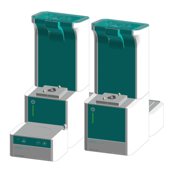
■■■■■■■■■■■■■■■■■■■■■■ Functional description OMNIS Titrator – Single-workplace KF titration sys- tem volumetric – Overview Figure 3 Single-workplace Karl Fischer titration system (volumetric) – Front Measuring Module Analog, installed Cylinder unit For the Karl Fischer titration, we recommend using the 10-mL cylinder units. -
Page 22: System - Signals
OMNIS Titrator – Single-workplace KF titration system volumetric – Overview ■■■■■■■■■■■■■■■■■■■■■■ 3.2.1 System – Signals Visual signals All products and components of the system that are equipped with multi- color status displays indicate their respective status using colors and flash- ing patterns. -
Page 23: Omnis Titrator - Overview
For connecting the OMNIS Liq- uid Adapter. Local Area Network For connecting the product to a local network. USB connector For connecting USB devices. OMNIS Titrator – Overview Figure 4 OMNIS Titrator – Front Space for measuring modules Dosing drive Magnetic stirrer Platform For chemical bottles ■■■■■■■■... - Page 24 Cable guide On the side to the right. For Liquid Adapter cable MSI connector Cable guide MSI = Metrohm Solution Identification. Con- Bottom right nection socket for Liquid Adapter cable Interfaces Cable guide System – Interfaces (see chapter 3.2.2, page...
-
Page 25: Magnetic Stirrer - Overview
■■■■■■■■■■■■■■■■■■■■■■ Functional description 3.3.1 Magnetic stirrer – Overview Figure 6 Magnetic stirrer – Overview Stand attachment Stirring area Control bar Status display LED. Multi-colored ■■■■■■■■... -
Page 26: Magnetic Stirrer With Accessories - Overview
OMNIS Titrator – Overview ■■■■■■■■■■■■■■■■■■■■■■ 3.3.2 Magnetic stirrer with accessories – Overview Figure 7 Magnetic stirrer with accessories – Overview Support rod Electrode holder Clamping ring Control bar ■■■■■■■■... -
Page 27: Dosing Unit - Overview
■■■■■■■■■■■■■■■■■■■■■■ Functional description 3.3.3 Dosing unit – Overview Figure 8 Dosing unit – Overview Cylinder unit Dosing drive Available with various volumes Not in scope of delivery ■■■■■■■■... - Page 28 OMNIS Titrator – Overview ■■■■■■■■■■■■■■■■■■■■■■ Figure 9 Dosing drive – Overview Status display Contact pins LED. Multi-colored For communicating with the cylinder unit Twistlocks Piston rod For locking the cylinder unit For moving the dosing piston Valve coupling ■■■■■■■■...
- Page 29 ■■■■■■■■■■■■■■■■■■■■■■ Functional description 3.3.3.1 Cylinder unit OMNIS – Overview Figure 10 Cylinder unit – Overview Distributor with 4 ports Cylinder top piece Cylinder housing Centering tube Cylinder Data chip Piston stopper Dosing piston Spring clip 10 Unlocking button ■■■■■■■■...
- Page 30 OMNIS Titrator – Overview ■■■■■■■■■■■■■■■■■■■■■■ Figure 11 Cylinder unit – Overview from above The following table shows the standard use of the 4 ports. The use of the ports can be changed in the OMNIS Software. Port Connecting or sealing...
-
Page 31: Bottle Unit - Overview
■■■■■■■■■■■■■■■■■■■■■■ Functional description 3.3.4 Bottle unit – Overview Figure 12 Bottle unit OMNIS Liquid Adapter Bottle cap multi-use Chemical bottle ■■■■■■■■... - Page 32 OMNIS Titrator – Overview ■■■■■■■■■■■■■■■■■■■■■■ 3.3.4.1 OMNIS Liquid Adapter – Overview Figure 13 OMNIS Liquid Adapter – Parts Cable Status display RFID reader Aspiration tube Part of 6.01600.xxx Tubing adapter Part of 6.01600.xxx ■■■■■■■■...
- Page 33 ■■■■■■■■■■■■■■■■■■■■■■ Functional description 3.3.4.2 Bottle cap multi-use – Overview Figure 14 Bottle cap multi-use, complete (6.01601.000) Flip-top lid Aspiration tubing Aspiration tubing (6.1819.020) RFID tag PTFE sealing ring RFID chip for contact-free data transmission. PTFE sealing ring (6.02701.010) Absorption cartridge insert Absorption cartridge housing (2 pieces) Absorption cartridge lid...
-
Page 34: Measuring Module Analog - Overview
OMNIS Titrator – Overview ■■■■■■■■■■■■■■■■■■■■■■ 3.3.5 Measuring Module Analog – Overview Figure 15 Measuring Module Analog – Overview INPUT 1 INPUT 2 Connection socket for potentiometric sen- Connection socket for potentiometric sen- sors (green coding), temperature sensors sors (green coding) and temperature sensors... -
Page 35: Measuring Module Digital - Overview
■■■■■■■■■■■■■■■■■■■■■■ Functional description 3.3.6 Measuring Module Digital – Overview Figure 16 Measuring Module Digital – Overview Fastening screws Connection socket Fastening screws, left and right. These fasten For dTrodes the measuring module in the housing and ground the electronics. ■■■■■■■■... -
Page 36: Omnis Product With A Volumetric Kf Titration Cell - Overview
OMNIS Titrator – Overview ■■■■■■■■■■■■■■■■■■■■■■ 3.3.7 OMNIS product with a volumetric KF titration cell – Overview Figure 17 OMNIS product with an installed volumetric KF titration cell Support rod Locking lever KF titration vessel lid Clamping ring Titration vessel Control bar for stirrer... -
Page 37: Omnis Titrator - Function
■■■■■■■■■■■■■■■■■■■■■■ Functional description OMNIS Titrator – Function The OMNIS Titrator is equipped with the following functional units: Connections to the power grid and the local network. ■ Interfaces for connecting additional modules. ■ Slots for a maximum of two measuring modules. -
Page 38: Bottle Unit - Function
OMNIS Titrator – Function ■■■■■■■■■■■■■■■■■■■■■■ Rotating the cylinder: ■ The rotation of the cylinder controls which of the 4 ports the solution flows through. The valve disk with an opening is located in the middle of the cylinder base. The distributor disk with 4 openings corresponding to the 4 ports of the distributor is located at the bottom in the cylinder top piece. -
Page 39: Measuring Module Analog - Functional Description
Measuring Module Analog – Functional description The Measuring Module Analog is used as an interface for analog electro- des on an OMNIS Titrator or an OMNIS Titration Module. The Measuring Module Analog contains the electronics necessary for the use of analog sensors. Analog electrodes and analog reference electrodes can be plugged into its connection sockets. -
Page 40: Magnetic Stirrer - Indicators And Controls
OMNIS Titrator – Function ■■■■■■■■■■■■■■■■■■■■■■ Seepage of moisture into the KF titration cell is prevented with seals and with the adsorber tube, which is filled with molecular sieve. 3.4.7 Magnetic stirrer – Indicators and controls Figure 18 Magnetic stirrer – Control bar... -
Page 41: Omnis Main Instrument - Indicators And Controls
■■■■■■■■■■■■■■■■■■■■■■ Functional description NOTICE The stirrer can also be controlled via the software. Other functions in the software The following functions can be executed only with the OMNIS Software: Setting the stirring direction. ■ Deactivating keys. ■ The magnetic stirrer can be operated only via the software. Switching over the keys for the rod stirrer. -
Page 42: Magnetic Stirrer - Indicators And Controls
Magnetic stirrer – Indicators and controls ■■■■■■■■■■■■■■■■■■■■■■ Table 2 Behavior of the on/off switch Pressure duration Acoustic signal Function on the OMNIS main instrument Short pressing (1 to 5 s) Switch on the instrument. Beep after 1 s Shut down the instrument. Very long pressing (>... - Page 43 ■■■■■■■■■■■■■■■■■■■■■■ Functional description NOTICE The most recently used stirring rate will be used again when the instrument is switched on. The current stirring rate is displayed in the software under Manual con- trol. NOTICE The stirrer can also be controlled via the software. Other functions in the software The following functions can be executed only with the OMNIS Software: Setting the stirring direction.
-
Page 44: Omnis Titrator - Interfaces
OMNIS Titrator – Interfaces ■■■■■■■■■■■■■■■■■■■■■■ OMNIS Titrator – Interfaces Figure 21 OMNIS Titrator – Interfaces and connectors MSI connector MDL connectors MSI = Metrohm Solution Identification. Con- MDL = Metrohm Device Link. Connection nection socket for Liquid Adapter cable socket for connecting cable between OMNIS... -
Page 45: Measuring Module Analog - Interfaces
■■■■■■■■■■■■■■■■■■■■■■ Functional description Measuring Module Analog – Interfaces The Measuring Module Analog has 3 connection sockets for analog elec- trodes. Figure 22 Measuring Module Analog – Interfaces and connectors Connection socket INPUT 1 Connection socket INPUT 2 Connection socket REF Connection socket INPUT 1 and INPUT 2 The connection sockets INPUT 1 and INPUT 2 are marked with colored circle segments. -
Page 46: Measuring Module Digital - Interfaces
Measuring Module Digital – Interfaces ■■■■■■■■■■■■■■■■■■■■■■ Measuring Module Digital – Interfaces The Measuring Module Digital has 1 connection socket for a digital elec- trode. Figure 23 Measuring Module Digital – Interfaces and connectors Connection socket for digital electro- Connection socket The black marking around the connection socket indicates that only a cable of a digital electrode may be plugged in here. -
Page 47: Transport And Storage
■■■■■■■■■■■■■■■■■■■■■■ Transport and storage 4 Transport and storage Checking the delivery Immediately upon arrival of the merchandise, check the shipment against the delivery note to ensure completeness and absence of damage. Storing the packaging The product is supplied in extremely protective packaging together with the separately packed accessories. -
Page 48: Installation
As a basic rule, the installation of the system and of the new products and modules is handled by trained and instructed specialists from the Metrohm Company and/or its representative. Setting up the product The product has been developed for operation indoors and may not be used in explosive environments. -
Page 49: Attaching The Cylinder Unit Omnis
■■■■■■■■■■■■■■■■■■■■■■ Installation Attaching the cylinder unit OMNIS NOTICE Default settings for the ports 1 and 2 Port 1 is defined as dosing port and port 2 as fill port in the data chip default settings of the cylinder unit. The following instructions describe the default setting. - Page 50 Attaching the cylinder unit OMNIS ■■■■■■■■■■■■■■■■■■■■■■ Titration tip (6.1543.200) ■ 1 Aligning the cylinder unit Rotate the cylinder unit until the marking with the label UNLOCK is in line with the marking on the dosing drive. Set the cylinder unit down onto the two twistlocks straight from above.
-
Page 51: Magnetic Stirrer - Installing The Accessories
■■■■■■■■■■■■■■■■■■■■■■ Installation 4 Mounting the tubings Tighten an FEP tubing (6.1805.100) into port 1. This FEP tubing is used as dosing tubing. Tighten the other end to the titration tip (6.1543.200). 5 Tighten the other FEP tubing (6.1805.100) into port 2. This FEP tubing is used as filling tubing. - Page 52 Magnetic stirrer – Installing the accessories ■■■■■■■■■■■■■■■■■■■■■■ Mounting the support rod Screw the support rod onto the stand attach- ment . Mounting the clamping ring Push the clamping ring over the support rod with the indent facing upward. ■■■■■■■■...
- Page 53 ■■■■■■■■■■■■■■■■■■■■■■ Installation Mounting the electrode holder Press the green locking lever on the elec- trode holder. Push the electrode holder over the support rod. To fix in place, release the green locking lever at the desired height. The electrode holder is fixed in place. NOTICE The clamping ring is used as the lower stop for the electrode holder.
-
Page 54: Omnis Karl Fischer Products - Replacing The Adsorber Material
OMNIS Karl Fischer products – Replacing the adsorber material ■■■■■■■■■■■■■■■■■■■■■■ Preparing the magnetic stirrer for operation Placing beaker and stirring bar Place a 16 mm (6.1903.020) or 25 mm (6.1903.030) PTFE stirring bar in the sam- ple beaker. Place the sample beaker on the contact surface of the magnetic stirrer. - Page 55 NOTICE The molecular sieve can be regenerated at 300 °C in the drying oven, see https:// www.metrohm.com/en/support-und-serv- ice/faq-kft/. 3. Filling the housing with adsorber material Place a cotton plug loosely at the base of the housing. Do not pack the cotton too tightly as sufficient gas flow has to be pos- sible.
-
Page 56: Omnis System - Mounting The Measuring Module
With this, you always know when it was last filled or replaced. OMNIS system – Mounting the measuring module Two measuring modules each can be installed in every OMNIS Titrator and in every OMNIS Titration Module. Each measuring module must be screwed tightly into the instrument to ensure trouble-free operation. - Page 57 ■■■■■■■■■■■■■■■■■■■■■■ Installation Opening the lid Open the lid of the titrator. Removing the side parts Carry out the following steps on both sides of the instrument. Remove the two screws from above using the hex key. Push the side covering upwards until it can be removed from the side.
- Page 58 OMNIS system – Mounting the measuring module ■■■■■■■■■■■■■■■■■■■■■■ Inserting the measuring module Insert the measuring module into an empty slot. The slots are designated with 1 (rear) and 2 (front). Attaching the measuring module Insert the fastening screws. Tighten the meas- uring module to the housing from both sides using the hex key.
-
Page 59: Measuring Module - Plugging In The Electrode Cable
■■■■■■■■■■■■■■■■■■■■■■ Installation Measuring module – Plugging in the electrode cable Plugging the electrode cable into the measuring module Align the red dot on the plug with the groove on the connection socket of the measuring input. Plug in the plug until you can feel it snap NOTICE It should be easy to plug in the plug. -
Page 60: Omnis Titrator - Mounting The Volumetric Karl Fischer Titration Cell
OMNIS Titrator – Mounting the volumetric Karl Fischer titration cell ■■■■■■■■■■■■■■■■■■■■■■ OMNIS Titrator – Mounting the volumetric Karl Fischer titration cell Setting up the volumetric KF titration cell Figure 25 Preparing the volumetric KF titration cell KF titration vessel lid KF titration vessel (6.01405.010) or... - Page 61 ■■■■■■■■■■■■■■■■■■■■■■ Installation NOTICE When doing so, ensure that the color marking on the KF titra- tion vessel aligns with the raised marking on the KF titration ves- sel lid. The scale of the volumetric KF titration cell will thus face towards you.
- Page 62 OMNIS Titrator – Mounting the volumetric Karl Fischer titration cell ■■■■■■■■■■■■■■■■■■■■■■ Preparing the volumetric KF titration cell 1 Insert the 3 screw nipples (26-1) in the M10 openings of the KF titra- tion vessel lid. 2 Insert the 2 screw nipples (26-2) in the M12 openings of the KF titra- tion vessel lid.
- Page 63 ■■■■■■■■■■■■■■■■■■■■■■ Installation The adsorber tube with lid (27-4) is filled with fresh molecular sieve, ■ see OMNIS Karl Fischer products – Replacing the adsorber material (see chapter 5.5, page 46). 1 Insert the dosing tip (27-1) in the M10 screw nipple on the left (26-1) and screw it tight.
- Page 64 OMNIS Titrator – Mounting the volumetric Karl Fischer titration cell ■■■■■■■■■■■■■■■■■■■■■■ Spoon for paste ■ Mounting the volumetric KF titration cell on the OMNIS product (e.g. OMNIS Titrator) Figure 28 Mounting the volumetric KF titration cell on the OMNIS product – Overview...
- Page 65 ■■■■■■■■■■■■■■■■■■■■■■ Installation NOTICE If you want to mount the volumetric KF titration cell on the OMNIS product for use with a homogenizer, you can find additional informa- tion under (see "Optional: Mounting the volumetric KF titration cell for use with homogenizer on the OMNIS product (e.g. OMNIS Titra- tor)", page 61).
- Page 66 OMNIS Titrator – Mounting the volumetric Karl Fischer titration cell ■■■■■■■■■■■■■■■■■■■■■■ 5 Fix the clamping ring in place at the desired position with the knurled screw. The position of the KF titration cell is now fixed by the clamping ring.
- Page 67 ■■■■■■■■■■■■■■■■■■■■■■ Installation M8 PTFE tubing between dosing tip M6 PTFE tubing between buret tip and and reagent bottle (Solvent) dosing port 1 of cylinder unit Dosing tip (6.1543.110) with M8 PTFE tub- For adding the titrant via the buret tip ing (6.1805.200) leading to the reagent bot- (6.1543.200) with M6 PTFE tubing tle (Solvent)
- Page 68 OMNIS Titrator – Mounting the volumetric Karl Fischer titration cell ■■■■■■■■■■■■■■■■■■■■■■ Connecting a double Pt electrode to the analog measuring module Figure 30 Measuring Module Analog – Interfaces Connection socket INPUT 1 Connection socket INPUT 2 Connection socket REF Prerequisites: An electrode cable with blue coding is screwed tightly onto the double Pt electrode.
- Page 69 ■■■■■■■■■■■■■■■■■■■■■■ Installation Optional: Mounting the volumetric KF titration cell for use with homogenizer on the OMNIS product (e.g. OMNIS Titra- tor) Figure 31 Mounting the volumetric KF titration cell for use with homogenizer on the OMNIS product – Overview Holder for homogenizer Spacer 35 mm Holder for Polytron PT 1300 D (6.02008.010)
- Page 70 OMNIS Titrator – Mounting the volumetric Karl Fischer titration cell ■■■■■■■■■■■■■■■■■■■■■■ Support rod with mounted clamping KF titration vessel ring 20 – 90 mL (6.01406.220) or 50 – 150 mL (6.01406.250) Dispersing aggregate 10 Magnetic stirrer 125 mm (6.1912.000) or 157 mm (6.1912.010)
-
Page 71: Omnis System - Mounting The Electrode
■■■■■■■■■■■■■■■■■■■■■■ Installation 6 Connect the homogenizer handset (31-3) to the control instrument of the homogenizer (Polytron PT 1300 D). 7 Connect the homogenizer (Polytron PT 1300 D) (31-3) with the RS-232 cable to the PC. Hint: We recommend using the dispersing aggregates as follows: Dispersing aggregate 125 mm ■... - Page 72 OMNIS system – Mounting the electrode ■■■■■■■■■■■■■■■■■■■■■■ Inserting the electrode in the electrode holder Insert the electrode from above into the front opening of the electrode holder. Push the green upper part of the electrode downwards until it stops. The green part of the electrode is flush with the lower edge of the electrode holder.
- Page 73 ■■■■■■■■■■■■■■■■■■■■■■ Installation Unscrew and remove the protective cap from the electrode. Plug in the plug of the electrode cable. Observe the orientation (A). ■■■■■■■■...
-
Page 74: Omnis System - Mounting The Electrode Parking Station
OMNIS system – Mounting the electrode parking station ■■■■■■■■■■■■■■■■■■■■■■ Screw the electrode cable tight. 5.10 OMNIS system – Mounting the electrode parking station The electrode parking station is used for storing electrodes that are not being used. It can also be used for the storage vessels of electrodes that are currently being used. - Page 75 ■■■■■■■■■■■■■■■■■■■■■■ Installation View from below onto the side panel of the OMNIS product Tilt the OMNIS product to the side and insert the stand of the electrode parking station from below in the middle of the side panel. Correct end position of the electrode parking station Push the electrode parking station upwards as far as it will go in the direction of the instru-...
-
Page 76: Omnis Titration System - Mounting The Bottle Unit
OMNIS titration system – Mounting the bottle unit ■■■■■■■■■■■■■■■■■■■■■■ 5.11 OMNIS titration system – Mounting the bottle unit The bottle unit in an OMNIS system is comprised of the following ele- ments: Chemical bottle ■ OMNIS bottle cap ■ OMNIS Liquid Adapter ■... -
Page 77: Connecting/Disconnecting The Power Cord
■ sockets) against moisture. If you suspect that moisture has gotten into the product, discon- ■ nect the product from the energy supply. Then notify Metrohm Service. Only personnel who have been issued Metrohm qualification may ■ perform service and repair work on electrical and electronic com- ponents. - Page 78 Connecting/Disconnecting the power cord ■■■■■■■■■■■■■■■■■■■■■■ Power plug according to customer requirements (6.2122.XX0), designed for a minimum of 10 A. 1 Plugging in the power cord Plug the power cord into the product's power socket. ■ Connect the power cord to the energy supply. ■...
-
Page 79: Start-Up
Initial start-up by Metrohm NOTICE Initial start-up of the product As a basic rule, the initial start-up of the system and of the new prod- ucts and modules is handled by trained and instructed specialists from the Metrohm Company and/or its representative. ■■■■■■■■... -
Page 80: Operation And Control
Operation ■■■■■■■■■■■■■■■■■■■■■■ 7 Operation and control Operation NOTICE Operating via the control software The product can be operated using the commands of the control software. Additional information can be found in the software help . Switching the OMNIS main instrument on and off Switching the OMNIS main instrument on and off 1 Switching on an OMNIS main instrument Press the on/off switch... -
Page 81: Refitting The Cylinder Unit Omnis
■■■■■■■■■■■■■■■■■■■■■■ Operation and control The OMNIS main instrument cannot be switched off. 1 Forcing a shutdown Press the on/off switch for 8 seconds until the acoustic signal is heard in short intervals. The acoustic signal sounds for 2 seconds. The status display goes out and the OMNIS main instrument is switched off. - Page 82 Refitting the cylinder unit OMNIS ■■■■■■■■■■■■■■■■■■■■■■ Cylinder unit: The piston stopper is flush with the base of the cylinder ■ housing. The centering tube is in the correct position. 1 Removing the tubing Unscrew the dosing tubing and the filling tubing. 2 Unlocking the cylinder unit Rotate the cylinder unit to the right as far as the UNLOCK position.
-
Page 83: Attaching The Cylinder Unit Omnis
■■■■■■■■■■■■■■■■■■■■■■ Operation and control 3 Raising the cylinder unit Raise the cylinder unit straight upwards. See also Cylinder unit OMNIS – Overview (chapter 3.3.3.1, page 21) 7.3.2 Attaching the cylinder unit OMNIS NOTICE Default settings for the ports 1 and 2 Port 1 is defined as dosing port and port 2 as fill port in the data chip default settings of the cylinder unit. - Page 84 Refitting the cylinder unit OMNIS ■■■■■■■■■■■■■■■■■■■■■■ Attaching the cylinder unit NOTICE These instructions describe the default installation as defined in the OMNIS Software. Prerequisite: Dosing drive: Valve coupling and piston rod are in the exchange posi- ■ tion (port 2 is set). Cylinder unit: The piston stopper is flush with the base of the cylinder ■...
- Page 85 ■■■■■■■■■■■■■■■■■■■■■■ Operation and control 3 Locking the cylinder unit Rotate the cylinder unit to the left until it stops. Use the marking with the label LOCK as a guide. 4 Mounting the tubings Tighten an FEP tubing (6.1805.100) into port 1. This FEP tubing is used as dosing tubing.
-
Page 86: Magnetic Stirrer - Operation
Magnetic stirrer – Operation ■■■■■■■■■■■■■■■■■■■■■■ 6 Firmly tighten the tubing with the wrench (6.2739.000). See also Cylinder unit OMNIS – Overview (chapter 3.3.3.1, page 21) Magnetic stirrer – Operation The magnetic stirrer can be operated in two different ways: manually at press of the buttons on the instrument ■... -
Page 87: Setting The Stirring Rate
■■■■■■■■■■■■■■■■■■■■■■ Operation and control 7.4.2 Setting the stirring rate The stirring rate can be adjusted in 15 steps. Setting the stirring rate Prerequisites The stirrer is switched on. ■ Proceed as follows: 1 Increasing the stirring rate in stages Press the key repeatedly. -
Page 88: Maintenance
Only perform maintenance work that is described in this instruction. Con- tact the Metrohm service for further maintenance and repairing works. Disconnect the product from the power grid prior to any maintenance and cleaning. -
Page 89: Maintenance Agreement
■ sockets) against moisture. If you suspect that moisture has gotten into the product, discon- ■ nect the product from the energy supply. Then notify Metrohm Service. Only personnel who have been issued Metrohm qualification may ■ perform service and repair work on electrical and electronic com- ponents. -
Page 90: Cleaning The Product
■ sockets) against moisture. If you suspect that moisture has gotten into the product, discon- ■ nect the product from the energy supply. Then notify Metrohm Service. Only personnel who have been issued Metrohm qualification may ■ perform service and repair work on electrical and electronic com- ponents. -
Page 91: Cleaning The Omnis Liquid Adapter
Maintenance NOTICE If the suspicion arises that liquids have found their way into the product, disconnect the product from the power grid and con- tact your Metrohm Service. NOTICE Water or ethanol can be used as a cleaning medium. NOTICE The connectors at the rear of the product must only be cleaned with a dry cloth. - Page 92 Cleaning the product ■■■■■■■■■■■■■■■■■■■■■■ Cleaning the OMNIS Liquid Adapter CAUTION Instrument damage through inward seepage of liquid Property damage to the instrument or malfunction through the inward seepage of liquids (e.g. when cleaning). The instrument is not resistant to splash water. Water can seep into the interior during cleaning and cause damage (e.g.
-
Page 93: Checking And Replacing Product Parts
■■■■■■■■■■■■■■■■■■■■■■ Maintenance In order to access the lowered part better, set the OMNIS Liquid Adapter on a table edge. Push the OMNIS Liquid Adapter down and keep it pushed down. The lowered part rises. Thoroughly wipe the surface and the slot for the aspiration tube with a damp cloth. - Page 94 ■ sockets) against moisture. If you suspect that moisture has gotten into the product, discon- ■ nect the product from the energy supply. Then notify Metrohm Service. Only personnel who have been issued Metrohm qualification may ■ perform service and repair work on electrical and electronic com- ponents.
-
Page 95: Malfunctions And Troubleshooting
Malfunctions have to be solved directly on the product. If applicable, ■ this can be done with the help of the control software (e.g. initializa- tion, move to defined position, etc.). NOTICE Additional information can be found in the context-sensitive software help or on https://guide.metrohm.com. ■■■■■■■■... -
Page 96: Disposal
■■■■■■■■■■■■■■■■■■■■■■ 10 Disposal This product is covered by European Directive, WEEE – Waste Electrical and Electronic Equipment. The correct disposal of your old product will help to prevent negative effects on the environment and public health. More details about the disposal of your old product can be obtained from your local authorities, from waste disposal companies or from your local dealer. -
Page 97: Technical Specifications
+5 to +45 °C max. 80% relative humidity, non- condensing Storage +5 to +45 °C 11.2 OMNIS Titrator – Energy supply Nominal voltage range 100 VAC - 240 VAC Nominal frequency range 50 Hz - 60 Hz Power consumption max. 100 W... -
Page 98: Omnis Measuring Module - Energy Supply
OMNIS Measuring Module – Energy supply ■■■■■■■■■■■■■■■■■■■■■■ 11.4 OMNIS Measuring Module – Energy supply Power consumption max. 0.6 W Energy transmission inductive coupling 11.5 OMNIS Titrator – Dimensions Measurements Width 142 mm Height 358 mm Depth Without magnetic stirrer 284 mm... -
Page 99: Omnis Magnetic Stirrer - Dimensions
OMNIS Magnetic Stirrer – Dimensions Measurements Width 142 mm Height 70 mm Depth 116 mm Weight 700 g 11.8 OMNIS Titrator – Housing Materials poly(ethylene tereph- thalate) Back panel AW-5754 H12/H22 aluminum, coated Base 1.4301 high-grade steel Enclosure poly(butylene tereph-... -
Page 100: Omnis Magnetic Stirrer - Housing
Enclosure thalate) Front foils poly(butylene tereph- thalate), mat IP degree of protection IP 40 11.11 OMNIS Titrator – Connectors specifications Energy supply via power connection Socket IEC 60320, type C14, 10 A Power cord Length max. 2 m... -
Page 101: Omnis Measuring Module Analog - Connectors Specifications
Type Ethernet CAT 6 Socket RJ45 shielded Cable type (min. FFTP) shielded Cable length max. 10 m from Metrohm accesso- ries (link) Measuring module 2 slots max. 0.6 W per measuring module Power output Energy transmission inductive coupling Data transmission... -
Page 102: Omnis Measuring Module Digital - Connectors Specifications
11.13 OMNIS Measuring Module Digital – Connectors specifications dTrode socket Type round plug 6-pin, size 0, 60° Digital electrode connector of a dTrode 11.14 OMNIS Titrator – Display specifications Status display multi-colored 11.15 OMNIS Measuring Module Digital – Display specifi- cations Status display green ■■■■■■■■... - Page 103 ■■■■■■■■■■■■■■■■■■■■■■ Technical specifications 11.16 OMNIS Measuring Module Analog – Measuring spec- ifications Potentiometric Measuring range –2400 mV - +2400 mV Resolution 1.56 µV Measuring accuracy ±0.5 mV in the measuring range –2,000 mV - +2,000 Input resistance ≥ 1*10 Ω Offset current ≤...
- Page 104 Measuring accuracy applies for all measur- ing ranges without sen- sor error, under refer- ence conditions, meas- uring interval 100 ms 11.17 OMNIS Titrator – Liquid Handling specifications Dosing drive 100,000 steps per cylinder vol- Dosing resolution Dosing accuracy 0.01%...
- Page 105 ■■■■■■■■■■■■■■■■■■■■■■ Technical specifications Rotational speed change per step 120 rpm Maximum rotational speed 1,800 rpm Magnetic stirring bar lengths 8, 12, 16, 25, 30 mm ■■■■■■■■...
Need help?
Do you have a question about the OMNIS Titrator and is the answer not in the manual?
Questions and answers