Table of Contents
Advertisement
Quick Links
Advertisement
Table of Contents

Subscribe to Our Youtube Channel
Related Manuals for Metrohm OMNIS


Summary of Contents for Metrohm OMNIS
- Page 1 OMNIS Sample Robot WSM 2.101x.0120 Product manual 8.1012.8003EN / v1 / 2024-10-03...
-
Page 3: Product Manual
Metrohm AG Ionenstrasse CH-9100 Herisau Switzerland +41 71 353 85 85 info@metrohm.com www.metrohm.com OMNIS Sample Robot WSM Product manual 8.1012.8003EN / v1 / 2024-10-03... - Page 4 Disclaimer Deficiencies arising from circumstances that are not the responsibility of Metrohm, such as improper storage or improper use, etc., are expressly excluded from the warranty. Unauthorized modifications to the product (e.g., conversions or attachments) exclude any liability on the part of the manufacturer for resulting damage and its consequences.
-
Page 5: Table Of Contents
Table of contents 1 Overview Product description .............. 1 Upgrade options ..............1 OMNIS Main Module WSM – Product versions ....1 Workstation module – Product versions ......2 About the documentation ........... 2 Further information .............. 3 Displaying accessories ............3 2 Safety Intended use ................. - Page 6 Connecting the inlet tubing and the outlet tubing ..34 Plugging in the power cord ..........35 6 Operation Switching on and off ............37 Attaching and removing the OMNIS sample rack ... 38 7 Maintenance Replacing the gripper finger tips ........40 Replacing the beaker adapter ........... 43 Replacing the titration head ..........
- Page 7 ■■■■■■■■■■■■■■■■■■■■■■ Table of contents 10.7 Peristaltic pumps – Specifications ........65 10.8 Magnetic stirrer – Specifications ........65 10.9 Sample handling specifications ......... 66 ■■■■■■■■...
-
Page 9: Overview
Overview 1 Overview Product description The OMNIS Sample Robot WSM is a modular system for automated sam- ple changes in titrations. The modular construction makes it possible to configure the system in accordance with the area of application. Upgrade options... -
Page 10: Workstation Module - Product Versions
Workstation module – Product versions ■■■■■■■■■■■■■■■■■■■■■■ (01) = Article number in accordance (21) = Serial number with GS1 standard (240) = Metrohm article number Certification Certification Technical specifications Workstation module – Product versions The product is available in the following versions:... -
Page 11: Further Information
Metrohm Knowledge Base https://guide.metrohm.com – Thematically ■ filtered individual content, videos, information on OMNIS Software. Displaying accessories Up-to-date information on the scope of delivery and on optional accesso- ries can be found on the Metrohm website. 1 Searching for a product on the website Go to https://www.metrohm.com. - Page 12 – Click on [Optional parts] for the optional accessories. To download the accessories list, click on [Download accesso- ■ ries PDF] under Accessories and more. Metrohm recommends keeping the accessories list for refer- ence purposes. ■■■■■■■■...
-
Page 13: Safety
Safety 2 Safety Intended use Metrohm products are used for the analysis and handling of chemicals. Usage therefore requires the user to have basic knowledge and experience in handling chemicals. Knowledge regarding the application of fire preven- tion measures prescribed for laboratories is also mandatory. -
Page 14: Requirements For Operating Personnel
Always have maintenance work and repairs on electrical components ■ carried out by a regional Metrohm service representative. Disconnect the product from the energy supply immediately if at least ■ one of the following cases occurs: –... -
Page 15: Danger From Highly Flammable Substances
Dispose of chemically contaminated materials (e.g. cleaning material) in ■ accordance with regulations. Proceed as follows in case of a return shipment to Metrohm AG or a ■ regional Metrohm representative: – Decontaminate the product or product component. -
Page 16: Danger During Transport Of The Product
Design of warning messages ■■■■■■■■■■■■■■■■■■■■■■ 2.4.5 Danger during transport of the product Chemical or biological substances may be spilled during the transport of the product. Parts of the product may fall down or may be damaged. There is a risk of injury from chemical or biological substances and pieces of broken glass. -
Page 17: Meaning Of Warning Signs
■■■■■■■■■■■■■■■■■■■■■■ Safety DANGER Indicates an immediate danger. It will result in serious injuries or death if not avoided. WARNING Indicates a potential danger. Failure to avoid the danger may result in death or serious injury. CAUTION Indicates a potential danger. If not avoided, it may result in light or minor injuries. -
Page 18: Functional Description
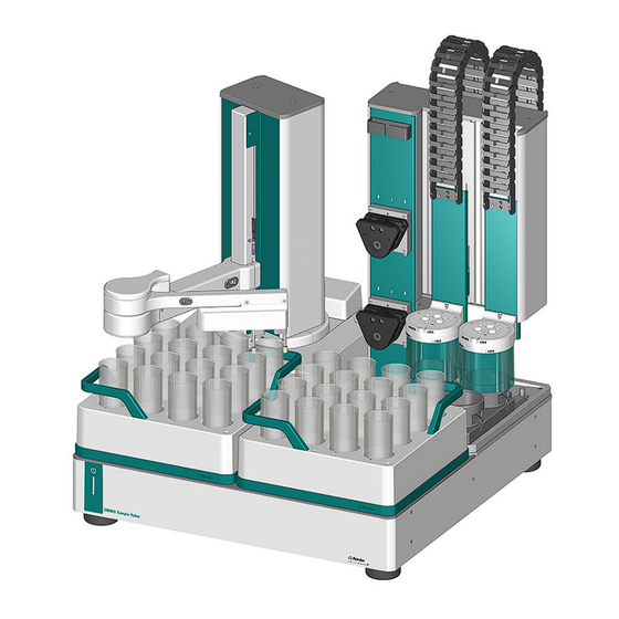
3 Functional description OMNIS Sample Robot WSM – Overview The OMNIS Sample Robot WSM is a modular system for automated sam- ple changes in titrations. The modular construction makes it possible to configure the system in accordance with the area of application. - Page 19 ■■■■■■■■■■■■■■■■■■■■■■ Functional description Figure 2 OMNIS Sample Robot M – WSM OMNIS Main Module M – WSM Workstation module Figure 3 OMNIS Sample Robot L – WSM OMNIS Main Module L – WSM Workstation module ■■■■■■■■...
-
Page 20: Omnis Main Module Wsm - Overview
3.1.1 OMNIS Main Module WSM – Overview The OMNIS Main Module WSM supplies all of the attached modules in the OMNIS sample robot system with electricity. The control hardware is inte- grated in the interior of the OMNIS Main Module WSM. -
Page 21: Robot Arm - Movement Capacity
■■■■■■■■■■■■■■■■■■■■■■ Functional description 3.1.2 Robot arm – Movement capacity Figure 5 Main lift Main lift Arm holder The main lift (5-1) can be rotated to the left and right. The arm holder (5-2) on the main lift moves the robot arm up and down. Figure 6 Robot arm Lift arm... -
Page 22: Workstation Module - Overview
OMNIS Sample Robot WSM – Overview ■■■■■■■■■■■■■■■■■■■■■■ 3.1.3 Workstation module – Overview Figure 7 Front – Workstation module Guide chain Titration head holder Safety shield Slide Collection tray Lift tower Peristaltic pumps Tubing organizer Slide The slide (7-4) positions the sample beaker under the titration head holder. - Page 23 (see figure 8, page 16) and numbered 3 and 4. 2 peristaltic pumps are assigned to each workstation in the OMNIS Sample Robot WSM: 1 rinsing pump and 1 aspiration pump. The upper peristaltic pump (numbered 1 or 3) is used for rinsing off the ■...
- Page 24 OMNIS Sample Robot WSM – Overview ■■■■■■■■■■■■■■■■■■■■■■ Figure 8 Rear – Workstation module Tubing organizer Type label Drain nozzle Tubing organizer Grounding socket Distributor The distributor is located at the rear (8-6). This is used to connect the rins- ing tubing and aspiration tubing.
- Page 25 The standard lid seals were designed for aqueous applications and Karl Fischer titrations. If more aggressive solvents such as chlorobenzene or glacial acetic acid are used, then Metrohm recommends using the sample beaker lids (Dis-Cover lids) without lid seals .
- Page 26 Available lid trays Article Designation number 6.02007.010 Lid tray for OMNIS Sample Robot S 6.02007.020 Lid trays for OMNIS Sample Robot M/L 6.05800.070 Lid tray upgrade for OMNIS Sample Robot S to M/L Option for working with a homogenizer (Polytron PT 1300 A homogenizer (Polytron PT 1300 D) can be inserted in the titration head for homogenization of the sample.
-
Page 27: Omnis Sample Rack - Overview
OMNIS sample rack to be trans- ported by hand so that it can be set down on or removed from the rack holder of the rack base. Several empty OMNIS sample racks can be stacked on top of one another on the transport handles. -
Page 28: Indicators And Controls
(1 s) Switching on the device A beep sounds as soon as the LED flashes yellow (instrument can be reserved by an OMNIS system) press briefly (2 s) Shut down the instrument Beep after 2 s press and hold... -
Page 29: System - Signals
■■■■■■■■■■■■■■■■■■■■■■ Functional description System – Signals System components with status indicators show their operating status with colors and/or flashing patterns. The meaning of the colors and flash- ing patterns is explained in the following table. Visual signal Meaning LED lights up yellow. System start or initialization LED flashes yellow (slowly). -
Page 30: Connectors
Figure 13 Connections on the rear Ethernet network connection or LAN MDL connectors connector MDL = Metrohm Device Link LAN = Local Area Network. Connection socket for connecting cables between OMNIS products Connection socket for a connecting cable to the local network... -
Page 31: Delivery And Packaging
■■■■■■■■■■■■■■■■■■■■■■ Delivery and packaging 4 Delivery and packaging Delivery Inspect the delivery immediately upon receipt: Check the delivery against the delivery note to ensure completeness. ■ Check the product for damage. ■ If the delivery is incomplete or damaged, contact your regional Met- ■... -
Page 32: Installation
Lift the Sample robot on all 4 sides or transport it on a continuous ■ plate to avoid sagging. Check the positioning accuracy of the sample robot after placing the ■ sample robot down. If inaccuracies occur, contact the regional Metrohm service representa- ■ tive for a readjustment. ■■■■■■■■... -
Page 33: Mounting The Safety Shield
Use the product only with the coverings mounted. ■ If coverings are damaged or missing, then disconnect the product ■ from the energy supply and contact a regional Metrohm service representative. Always have maintenance work and repairs on electrical compo- ■... -
Page 34: Connecting The Workstation Module
Connecting the workstation module ■■■■■■■■■■■■■■■■■■■■■■ 2 Fastening the safety shield Figure 15 Fastening the safety shield Rotate the safety shield in the direction of the arrow until the ■ marking points to "LOCK". Connecting the workstation module Mounting the WSM connector plate Prerequisite: The sample robot is switched off ■... -
Page 35: Connecting The Tubing To The Distributor Of The Workstation Module
■■■■■■■■■■■■■■■■■■■■■■ Installation 2 Positioning and fastening the WSM connector plate Figure 17 Positioning and fastening the WSM connector plate Position the WSM connector plate above the two workstation ■ modules. Attach the WSM connector plate to the two workstation modules ■... - Page 36 Connecting the tubing to the distributor of the workstation module ■■■■■■■■■■■■■■■■■■■■■■ Distributor Rinsing pump outlet tubing Aspiration pump inlet tubing Connecting the tubing to the distributor Prerequisite: The sample robot is switched off ■ 1 Connecting the rinsing tubing Manually tighten or plug in the three rinsing tubings (18-1) in the bores of the distributor (18-3).
-
Page 37: Mounting The Drainage Conduit
■■■■■■■■■■■■■■■■■■■■■■ Installation Mounting the drainage conduit The execution and mounting position of the drainage conduit differs, depending on the version of the OMNIS Sample Robot: OMNIS Sample Robot M – WSM OMNIS Sample Robot ■ L – WSM, the drainage conduit is mounted below the workstation (see "Preparing and mounting the drainage conduit –... - Page 38 Mounting the drainage conduit ■■■■■■■■■■■■■■■■■■■■■■ Screws (supplied) Connection bracket Tubing to waste canister Tubing, 160 mm Y tubing connector (6.01808.010) Tubing, 35 mm Tubing, 270 mm Preparing and mounting the drainage conduit – M and L Required accessories: 1 tubing (6.01803.000) for connecting to the tubing adapter and the ■...
- Page 39 ■■■■■■■■■■■■■■■■■■■■■■ Installation Figure 20 Mounting the drainage conduit The drainage conduit can be mounted in 2 different directions to adjust the orientation of the drainage to the local installa- tion. Check if the drainage conduit is correctly oriented. ■ If necessary, mount the drainage conduit the other way round ■...
- Page 40 Ensure that the tubing points as straight as possible into the waste canister. Preparing and mounting the drainage tubing – OMNIS Sample Robot S – WSM Required accessories: 1 tubing (6.01803.000) for connecting to the tubing adapter and the ■...
- Page 41 ■■■■■■■■■■■■■■■■■■■■■■ Installation 2 Cutting to length and fastening the tubing Figure 23 Cutting to length and mounting the tubing Cut the tubing (6.01803.000) to length. The tubing should be ■ long enough to connect the drainage conduit with the waste can- ister.
-
Page 42: Connecting The Inlet Tubing And The Outlet Tubing
Connecting the inlet tubing and the outlet tubing ■■■■■■■■■■■■■■■■■■■■■■ Connecting the inlet tubing and the outlet tubing Figure 24 Connecting the inlet tubing and the outlet tubing Inlet tubing Outlet tubing Connecting element Luer tool Peristaltic pump Connecting the inlet tubing and the outlet tubing of the peristaltic pump Prerequisite: The sample robot is switched off... -
Page 43: Plugging In The Power Cord
Protect live components (e.g. power supply unit, power cord, con- ■ nection sockets) against moisture. Always have maintenance work and repairs on electrical compo- ■ nents carried out by a regional Metrohm service representative. Required accessories: Power cord: ■ – Length: max. 2 m –... - Page 44 Plugging in the power cord ■■■■■■■■■■■■■■■■■■■■■■ Power plug: ■ – 6.2122.XX0 (according to customer requirement), min. 10 A Figure 25 Plugging in the power cord Plug the power cord into the product's power socket. Use only ■ permitted power cords. Connect the power cord to the energy supply.
-
Page 45: Operation
■■■■■■■■■■■■■■■■■■■■■■ Operation 6 Operation The product can be operated via the OMNIS Software. Further information on the OMNIS Software under OMNIS Help. Switching on and off NOTICE Data loss Disconnecting OMNIS instruments from the power grid (e.g. with a connector strip) may lead to irreversible data loss. If the instrument can no longer be used, contact your regional Metrohm service repre- sentative. -
Page 46: Attaching And Removing The Omnis Sample Rack
Because of the shape of the rack holder and the counterpart on the OMNIS sample rack, the OMNIS sample rack can be attached to the rack base in only one position. A brief signal will sound as soon as the OMNIS sample rack is seated correctly on the rack holder. ■■■■■■■■... - Page 47 ■■■■■■■■■■■■■■■■■■■■■■ Operation Removing the OMNIS sample rack Grip the OMNIS sample rack on both transport handles (11-3) ■ remove it upwards. A brief signal will sound as soon as the OMNIS sample rack has been removed. ■■■■■■■■...
-
Page 48: Maintenance
Metrohm recommends having the products maintained by the regional ■ Metrohm service representative as part of an annual service. Shorter maintenance intervals may be necessary if you frequently work with caustic and corrosive chemicals. - Page 49 ■■■■■■■■■■■■■■■■■■■■■■ Maintenance Sleeve Finger tips Consumable Kit OMNIS Gripper (6.05700.000) Retainer Dismantling finger tips and sleeves Prerequisite: The sample robot is switched off. ■ There is no beaker in the gripper. ■ If you are using a gripper with retainer (27-5), lift the retainer off the gripper beforehand.
- Page 50 Replacing the gripper finger tips ■■■■■■■■■■■■■■■■■■■■■■ 4 Make sure that the finger tip is firmly seated on the gripper finger and that it can still be rotated. 5 Place the retainer, if applicable, back onto the gripper with retainer. The gripper with retainer must always be operated with the retainer! This ensures that the beakers are always gripped correctly.
-
Page 51: Replacing The Beaker Adapter
■■■■■■■■■■■■■■■■■■■■■■ Maintenance 2 Use the other hand to pull the finger tip (28-3) horizontally and off the gripper finger (28-2) by applying gentle rotating movements. Assembling the finger tips Prerequisite: The sample robot is switched off. ■ The finger tips are disassembled. ■... - Page 52 Replacing the beaker adapter ■■■■■■■■■■■■■■■■■■■■■■ Beaker volume Beaker diameter Beaker height Article number 150 mL 62 mm 96 mm 6.01404.050 200 mL 70 mm 100 mm 6.01404.020 250 mL 64.7 mm 113 mm no adapter required Replacing the beaker adapter Prerequisite: The sample robot is switched off ■...
- Page 53 ■ of the slide. Make sure that the correct values for the beaker diameter and beaker height (see "Available beaker adapters and settings" table) are entered for the respective workstation module in the OMNIS Soft- ware. Instruments Proper- The value can be changed in the...
-
Page 54: Replacing The Titration Head
■■■■■■■■■■■■■■■■■■■■■■ When changing to another beaker size, make sure to also take the titration head into account. Metrohm recommends using the same titration head for the 150 mL beaker size as for the 200 mL beaker size (6.01403.060). 4 Fastening the ring... - Page 55 ■■■■■■■■■■■■■■■■■■■■■■ Maintenance Replacing the titration head Prerequisite: The sample robot is switched off. ■ All of the sensors in the titration head are dismounted. ■ The safety shield is dismounted. ■ 1 Removing the titration head Figure 35 Loosening the titration head Grip the titration head (34-1) with one hand and rotate it in the...
- Page 56 Replacing the titration head ■■■■■■■■■■■■■■■■■■■■■■ 2 Inserting the titration head Figure 37 Inserting the titration head Insert the titration head from the bottom into the titration head ■ holder. Figure 38 Fastening the titration head Rotate the titration head in the direction of the arrow until the ■...
-
Page 57: Replacing The Lid Seal
■■■■■■■■■■■■■■■■■■■■■■ Maintenance Beaker volume Stirring propel- Openings / designations Article number 120 mL 6.01900.030 3xSGJ14, 4x6.4mm 6.01403.030 120 mL 1xSGJ14, 2xM6, 1xM10, 6.01403.050 1x6.4mm 150 mL 6.01900.010 3xSGJ14, 4x6.4mm 6.01403.060 200 mL 6.01900.030 3xSGJ14, 4x6.4mm 6.01403.060 250 mL 6.01900.010 6xSGJ14, 3xSGJ9 6.01403.000 Replacing the lid seal Replace the lid seal of the KF Dis-Cover lid approx. -
Page 58: Checking The Pump Tubing
Checking the pump tubing ■■■■■■■■■■■■■■■■■■■■■■ 2 Mounting the lid seal Figure 40 Mounting the lid seal Check the lid seal for damage. Use only intact lid seals. ■ Press the lid seal over the lid bottom from below and press it into ■... -
Page 59: Replacing The Pump Tubing
■■■■■■■■■■■■■■■■■■■■■■ Maintenance The sample robot is disconnected from the energy supply. ■ 1 Removing the press clamp (see figure 43, page 52) 2 Checking the pump tubing Perform a visual inspection of the pump tubing. ■ Note any cracking or leaking liquid while doing so. If the pump tubing exhibits damage, then replace it without ■... - Page 60 Replacing the pump tubing ■■■■■■■■■■■■■■■■■■■■■■ Rotate the tubing counterclockwise using the Luer tool. ■ Remove the tubing upwards out of the peristaltic pump. ■ 2 Removing the press clamp Figure 43 Removing the press clamp Pull the press clamp on one side outwards by hand. ■...
- Page 61 ■■■■■■■■■■■■■■■■■■■■■■ Maintenance The pump tubing is positioned close to the inner rollers for optimum conveyance of the media. It is for that reason that a certain amount of force must be applied for disassembling the first connecting element. The pump tubing and its connecting elements are designed for this application of force.
- Page 62 Replacing the pump tubing ■■■■■■■■■■■■■■■■■■■■■■ Figure 46 Placing the pump tubing around rollers Place the pump tubing around the rollers. ■ Slide the second connecting element up on the other side until it ■ stops in the guide rail as well. The position of the pump tubing must be close and snug to the rollers for optimum conveyance of the media.
-
Page 63: Cleaning The Product Surface
■■■■■■■■■■■■■■■■■■■■■■ Maintenance Figure 48 Mounting the press clamp – Next side Plug the other side in as well with the lug in the guide rail and ■ push it in. Make sure that the press clamp is placed so that it is flush and ■... - Page 64 Protect live components (e.g. power supply unit, power cord, con- ■ nection sockets) against moisture. Always have maintenance work and repairs on electrical compo- ■ nents carried out by a regional Metrohm service representative. Prerequisite: The product is switched off and disconnected from the energy supply. ■ Required accessories: Cleaning cloth (soft, lint-free) ■...
-
Page 65: Troubleshooting
(e.g. initializing, moving to a defined position). See also System – Signals (chapter 3.3, page 21) OMNIS Sample Robot WSM – Troubleshooting CAUTION Jammed drive and components Risk of injury in the event of jammed, moving, and hot components. -
Page 66: Opening The Gripper Manually
Opening the gripper manually ■■■■■■■■■■■■■■■■■■■■■■ Opening the gripper manually Prerequisite: The instrument is at a standstill. ■ CAUTION Unsecured sample beakers If the gripper is opened, then unsecured sample beakers may fall down. Spilled chemicals may result in injuries. The product may be damaged by liquid seeping in. -
Page 67: Disposal
■■■■■■■■■■■■■■■■■■■■■■ Disposal 9 Disposal Properly dispose of chemicals and of the product to reduce negative effects on the environment and public health. Local authorities, waste dis- posal companies or dealers provide more detailed information on disposal. Observe the WEEE EU directive (WEEE = Waste Electrical and Electronic Equipment) for the proper disposal of waste electronic equipment within the European Union. -
Page 68: Technical Specifications
3,000 m. above sea level / min. 700 mbar Overvoltage category Pollution degree Calibration: Air (at 20 °C, 101.325 kPa) 10.2 Energy supply OMNIS Main Module WSM Nominal voltage range 100–240 V AC ±10% Nominal frequency range 50–60 Hz ±3% Power consumption max. -
Page 69: Dimensions
560 mm Width Height 750 mm Depth 560 mm Weight 36.0 kg OMNIS Main Module WSM Measurements OMNIS Main Module S – WSM Width 560 mm Height 600 mm Depth 560 mm Weight 23.1 kg OMNIS Main Module M – WSM... - Page 70 Dimensions ■■■■■■■■■■■■■■■■■■■■■■ Weight 32.2 kg OMNIS Main Module L – WSM Width 1,400 mm Height 600 mm Depth 560 mm Weight 34.5 kg Workstation module Measurements Width 280 mm Height 758 mm Depth 289 mm Weight 1T/0P 8.9 kg 1T/2P 10.1 kg...
-
Page 71: Housing
■■■■■■■■■■■■■■■■■■■■■■ Technical specifications 10.4 Housing OMNIS Main Module WSM Materials PBTP Poly(butylene tereph- thalate) Front and back panel AW-6060 Aluminum, coated Base AW-5754 Aluminum, not coated Enclosure PBTP Poly(butylene tereph- thalate) Polypropylene Front foils Poly(ethylene tereph- thalate), mat IP degree of protection... -
Page 72: Connectors
Connectors ■■■■■■■■■■■■■■■■■■■■■■ 10.5 Connectors OMNIS Main Module WSM Energy supply via power connection Socket IEC 60320, type C14, 10 A Power cord Length max. 2 m Number of conductors with protective ground Conductor cross-section min. 0.75 mm / 18 AWG... -
Page 73: Display Specifications
■■■■■■■■■■■■■■■■■■■■■■ Technical specifications 10.6 Display specifications Status display multi-colored 10.7 Peristaltic pumps – Specifications Workstation module 0, 2, 4 Peristaltic pump Quantity added 300 mL/min Aspiration volume 150 mL/min 10.8 Magnetic stirrer – Specifications Adjustment range for rotational +1 to +15 Rotation in counter- speed clockwise direction... - Page 74 Sample handling specifications ■■■■■■■■■■■■■■■■■■■■■■ 10.9 Sample handling specifications OMNIS Sample Robot WSM Robot arm Load 3.7 N typical Speed 15 mm/s - 75 mm/s Gripper type with beaker diameter Area 25.6 mm - 71.6 mm from Metrohm accesso- ries Rack positions Sample Robot S 1–2...
Need help?
Do you have a question about the OMNIS and is the answer not in the manual?
Questions and answers