
Subscribe to Our Youtube Channel
Related Manuals for HAKO Minuteman RoboScrub 20


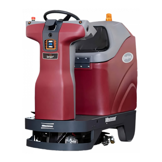
Summary of Contents for HAKO Minuteman RoboScrub 20
- Page 1 RoboScrub 20 Service Manual Minuteman International, Inc. A Member of the Hako Group...
-
Page 2: Table Of Contents
Table of Contents Technical Specifi cations ................4 Limited Warranty ..................6 Testing and Troubleshooting ..............8 3D Camera .................... 42 Modem ....................46 Steering ....................48 Enter Settings ..................52 Lower Lidar Removal ................78 Error Codes ................... 92 Testing Manual/Auto Switch .............. -
Page 3: Technical Specifi Cations
Technical Specifi cations RoboScrub Service Manual Page 4... - Page 4 RoboScrub Service Manual Page 5...
-
Page 5: Limited Warranty
Limited Warranty RoboScrub Service Manual Page 6... - Page 6 RoboScrub Service Manual Page 7...
-
Page 7: Testing And Troubleshooting
Testing and Troubleshooting Testing and Troubleshooting Drive System Disconnect Batteries RoboScrub Service Manual Page 8... - Page 8 Remove back panel RoboScrub Service Manual Page 9...
- Page 9 Secure panel for ease of access RoboScrub Service Manual Page 10...
- Page 10 Locate and disconnect P3 connector from controller RoboScrub Service Manual Page 11...
- Page 11 Place probes on pins 20 (BLK/PNK) and 10 (BLK/WHT). Set meter to OHMs. Depress Accelerator Pedal. Reading should be 0.3 (Static) to 1.7 (Full Throttle) RoboScrub Service Manual Page 12...
- Page 12 Plug P3 back into Controller. Place probes on Controller leads as shown. RoboScrub Service Manual Page 13...
- Page 13 1. Reconnect batteries. 2. Turn machine on. 3. Sit on seat to activate seat switch. 4. With meter in lap, select Forward on Right Touch Pad and depress Accelerator Pedal. At static (Stopped) voltage should be 0.0 VDC. As pedal is depressed the voltage should increase all the way up to 24 VDC. (Full Throttle) 5.
- Page 14 Testing Pedal Circuit Bypass Seat Switch Circuit RoboScrub Service Manual Page 15...
- Page 15 Bypass Seat Switch Circuit RoboScrub Service Manual Page 16...
- Page 16 Remove back access cover RoboScrub Service Manual Page 17...
- Page 17 Locate P3 connector on Kinetec Drive Controller and disconnect RoboScrub Service Manual Page 18...
- Page 18 Set meter to ohms. Place probes on PIN 20 (BLK/WHT WIRE) and PIN 10 (BLK/PINK WIRE) RoboScrub Service Manual Page 19...
- Page 19 Static Pedal(not pressed) should read 0.3 OHMS +/- 0.1 Fully activated pedal should read 1.7 OHMS +/- 0.1 *If reading not within above readings, replace* RoboScrub Service Manual Page 20...
- Page 20 THESE INSTRUCTIONS ARE A GUIDELINE FOR REPLACEMENT OF DRIVE WIRING PLATES FOR THE MR20 AUTONOMOUS MACHINE RoboScrub Service Manual Page 21...
- Page 21 REMOVE SCREW & WASHER FROM LARGE LOOSEN CHAIN TENSIONER SPROCKET TO GAIN CHAIN SLACK REMOVE MASTER LINK THEN REMOVE CHAN FROM SPROCKETS RoboScrub Service Manual Page 22...
- Page 22 LOOSEN BOTH SET SCREWS AND REMOVE SPROCKET REMOVE STEERING PIVOT FROM STEERING SPINDLE STOP AND KEY (NOT SHOWN) FROM STEERING SPINDLE RoboScrub Service Manual Page 23...
- Page 23 REMOVE STEERING SPINDLE/DRIVE MOTOR AND PLACE ON WORKBENCH RoboScrub Service Manual Page 24...
- Page 24 REMOVE OLD DRIVE WIRING PLATE AND REPLACE WITH NEW DRIVE WIRING PLATE RoboScrub Service Manual Page 25...
- Page 25 TIE WRAPS REINSTALL DRIVE MOTOR ORIENTED LIKE SHOWN. WRAP THE CABLE CONDUIT LOOSELY AROUND THE DRIVE MOTOR AND HOLD IN POSITION WITH TIE WRAPS INSTALL SUPPLEMENTAL DRIVE PLATE (SEE FOLLOWING PARTS DIAGRAM) RoboScrub Service Manual Page 26...
- Page 26 RoboScrub Service Manual Page 27...
- Page 27 ROTATE DRIVE MOTOR TO VERIFY CABLES ARTICULATE PROPERLY REASSEMBLE MACHINE IN REVERSE ORDER OF ASSEMBLY RoboScrub Service Manual Page 28...
- Page 28 Brake Release RoboScrub Service Manual Page 29...
- Page 29 Removing the MinuteMan Cowling, Wheel, E- MinuteMan RoboScrub 20 Stop, Key Switch, UI Screen and Control Console Removing the MinuteMan Cowling, Wheel, E-Stop, Key Switch, UI Screen and Control Console To remove the MinuteMan Cowling, remove the 5/32” hex screw on each side of the upper portion of the cowling, as well as the five 1/8”...
- Page 30 Removing the MinuteMan Cowling, Wheel, E- MinuteMan RoboScrub 20 Stop, Key Switch, UI Screen and Control Console The cowling can be lifted up and off the two hooks at the top of the unit. RoboScrub Service Manual Page 31...
- Page 31 Removing the MinuteMan Cowling, Wheel, E- MinuteMan RoboScrub 20 Stop, Key Switch, UI Screen and Control Console Use a ¾” socket to remove the locking nut and washer. Pull the wheel straight up to remove. There is a semi-circle key that is present. Be sure it does not fall out or get lost.
- Page 32 Removing the MinuteMan Cowling, Wheel, E- MinuteMan RoboScrub 20 Stop, Key Switch, UI Screen and Control Console Use a ¾” socket to remove the locking nut and washer. Pull the wheel straight up to remove. There is a semi-circle key that is present. Be sure it does not fall out or get lost.
- Page 33 Removing the MinuteMan Cowling, Wheel, E- MinuteMan RoboScrub 20 Stop, Key Switch, UI Screen and Control Console Use a 3/32” hex key to remove the two screws that secure the E-Stop. Slide over the metal lock to free the connector.
- Page 34 Removing the MinuteMan Cowling, Wheel, E- MinuteMan RoboScrub 20 Stop, Key Switch, UI Screen and Control Console Use a 3/32” hex key to remove the two screws that secure the Key Switch. Decouple the white connector to free the hardware.
- Page 35 Removing the MinuteMan Cowling, Wheel, E- MinuteMan RoboScrub 20 Stop, Key Switch, UI Screen and Control Console Use a 3/32” hex key to remove the four screws that secure the Control Console. Carefully unplug the two cables from the rear of the Control Console.
- Page 36 2D Camera D CAMERA If machine software does not boot up/freeze during start-up, the most likely cause is the right 2D camera is not working. This is the only camera that HAS TO BE WORKING for the software to boot up. RoboScrub Service Manual Page 37...
- Page 37 Disconnect the 2D Camera aff ected and check for 5VDC on pins 2 and 4. RoboScrub Service Manual Page 38...
- Page 38 If this is the right camera or front camera and voltage is present, please swap it with the left camera and test to ensure that the issue follows the camera. If the issue follows the camera it may need to be replaced. RoboScrub Service Manual Page 39...
- Page 39 If voltage is not present, test the following for continuity for the suspect camera. RoboScrub Service Manual Page 40...
- Page 40 If no continuity present, repalce UP TRUNK. RoboScrub Service Manual Page 41...
-
Page 41: 3D Camera
3D Camera 3D CAMERA If you receive a side IFM error, check to see if the camera has power. If the LED is blinking or lit the camera has power. In this case, try reseting the communication cable going to the camera on the UP Trunk as well as the UP Trunk connection on the BCM. - Page 42 If the LED is not blinking or lit, check voltage on the powet cable to confi rm ther is 24VDC. If there is power to camera may need to be replaced. RoboScrub Service Manual Page 43...
- Page 43 If you recdive a front IFM error, check to see if the camera has power. If the four LED’s on the front of the camera are blinking or lit, the camera has power. In this case, try resetting the communication cable going to the camera from the UP Trunk as well as the UP Trunk connection to the BCM.
- Page 44 If the four LED’s are not blinking or lit, check voltage on the power cable to confi rm there is 24VDC. If ther eis power the camera may need to be replaced. RoboScrub Service Manual Page 45...
-
Page 45: Modem
Modem MODEM From the modem, there are four connections which interface with the Modem: USB Power connector, micro USB Data connector and 2 antenna connectors: MIM01 and MIM02. RoboScrub Service Manual Page 46... - Page 46 Using a digital Multimeter, measure the voltage at the pins on the M12 female connector as shown below. (note the location of the M12 notch)(voltageshould be 5 VDC) If there is voltage measured across ALL three pins, contact tech support for further assistance. RoboScrub Service Manual Page 47...
-
Page 47: Steering
Steering Place steering wheel in zero position as shown below RoboScrub Service Manual Page 48... - Page 48 Verify that drive wheel is also in the zero position as shown below. RoboScrub Service Manual Page 49...
- Page 49 If Steering wheel and Drive wheel do not line up, remove front cowling and check for loose/missing Encoder set screws or slack/jumped gear in steering gear assembly. RoboScrub Service Manual Page 50...
- Page 50 Turn machine on when prompted enter Operator PIN 1337 RoboScrub Service Manual Page 51...
-
Page 51: Enter Settings
Enter Settings RoboScrub Service Manual Page 52... - Page 52 RoboScrub Service Manual Page 53...
- Page 53 Enter service PIN(if you do not have one contact Minuteman Tech Support RoboScrub Service Manual Page 54...
- Page 54 Enter Service Tools RoboScrub Service Manual Page 55...
- Page 55 Enter Steering RoboScrub Service Manual Page 56...
- Page 56 Enter Steering Assembly RoboScrub Service Manual Page 57...
- Page 57 Enter Sensor View RoboScrub Service Manual Page 58...
- Page 58 Move steering from left to right the return to zero position and recheck screen/encoder position. RoboScrub Service Manual Page 59...
- Page 59 Move steering fron left to right then return to the zero position and recheck screen / encoder position. RoboScrub Service Manual Page 60...
- Page 60 Move steering right until it stops. (Screen / encoder shoould line up with 90 degree mark) Do the same for the left. If off set return to zero and re-adjust. RoboScrub Service Manual Page 61...
- Page 61 Back out to Steering Assembly screen. Enter steering longevity. RoboScrub Service Manual Page 62...
- Page 62 Follow on-screen instructions RoboScrub Service Manual Page 63...
- Page 63 Follow on-screen instruction, press start. (Steering wheel will start moving left and right) After a minimim of 5 times in both directions, select cancel. RoboScrub Service Manual Page 64...
- Page 64 Back out to steering assembly screen and select run. RoboScrub Service Manual Page 65...
- Page 65 Follow on-screen instructions. RoboScrub Service Manual Page 66...
- Page 66 Continued RoboScrub Service Manual Page 67...
- Page 67 After Diagnostic run screen will show SUCCESS with a green check mark steps are complete. RoboScrub Service Manual Page 68...
- Page 68 Replacing the MinuteMan BCM MinuteMan RoboScrub 20 Replacing the MinuteMan BCM First, begin by disconnecting the battery connector at the rear of the machine. To remove the MinuteMan Cowling, remove the 5/32” hex screw on each side of the upper portion of the cowling, as well as the five 1/8”...
- Page 69 Replacing the MinuteMan BCM MinuteMan RoboScrub 20 The cowling can be lifted, up and off the two hooks at the top of the unit. RoboScrub Service Manual Page 70...
- Page 70 Replacing the MinuteMan BCM MinuteMan RoboScrub 20 Unscrew the four bundled black connectors that couple to the BCM. Decouple the fan connector. Cut the indicated zip ties and place the BCM to the side. Remove the six 3mm hex screws that secure the BCM.
- Page 71 Replacing the MinuteMan BCM MinuteMan RoboScrub 20 * Be sure to reconnect the green grounding cable (if present) when replacing the Brain Module. Follow the instructions in the reverse order to re-assemble. Power on the machine and make sure the robot can establish ROC connection.
- Page 72 Replacing the MinuteMan BCM MinuteMan RoboScrub 20 Site connectivity may be limited depending on building architecture or cellular signal infrastructure. Moving the scrubber to a different part of the property (or even outside the building) may improve connectivity. Train a short test route Print the home marker found on the following page.
- Page 73 Replacing the MinuteMan BCM MinuteMan RoboScrub 20 RoboScrub Service Manual Page 74...
- Page 74 Replacing the MinuteMan BCM MinuteMan RoboScrub 20 Enter the PIN code and select Teach Route. Teach a short route that starts and ends at the same home marker location. RoboScrub Service Manual Page 75...
- Page 75 Replacing the MinuteMan BCM MinuteMan RoboScrub 20 RoboScrub Service Manual Page 76...
- Page 76 Replacing the MinuteMan BCM MinuteMan RoboScrub 20 When replaying the short route, ensure that the robot follows the path without difficulty. At some point during the replay, step in the robots path and continue to block it until an assist is triggered.
-
Page 77: Lower Lidar Removal
Lower Lidar Removal Lower Lidar Removal RoboScrub Service Manual Page 78... - Page 78 Front Panel Removal RoboScrub Service Manual Page 79...
- Page 79 1. Remove these three screws. RoboScrub Service Manual Page 80...
- Page 80 2. Remove these two screws. Remove Upper Lidar cover plate. RoboScrub Service Manual Page 81...
- Page 81 3. Remove two nuts positioned inside frame underneath. There are two access holes to alow for removal. RoboScrub Service Manual Page 82...
- Page 82 RoboScrub Service Manual Page 83...
- Page 83 4. Remove screw on each side as shown in pictures below. RoboScrub Service Manual Page 84...
- Page 84 RoboScrub Service Manual Page 85...
- Page 85 Removal of lower jaw and Lidar. RoboScrub Service Manual Page 86...
- Page 86 1. Disconnect cables. RoboScrub Service Manual Page 87...
- Page 87 2. Remove these four screws. Then remove bracket. RoboScrub Service Manual Page 88...
- Page 88 KCCA0237 SCRUBBER CONTROLLER MOTOR MOTOR Ref_0V TRACTION+ TRACTION- BAT- BAT+ BRUSH+ BRUSH- VACUUM+ VACUUM- DGND +24V DIRTY WATER LEVEL SWITCH OEM DASHBOARD MODULE1 FRESH WATER LEVEL SWITCH MOTOR MOTOR MOTOR SEAT SWITCH UNLOAD LOAD TRACTION MOTOR BRUSH MOTOR VACUUM MOTOR BRUSH UNLOAD SWITCH BEACON DGND...
- Page 89 KCCA0237 SCRUBBER CONTROLLER SOCKET CONNECTION DETAILS FOR P1 MINUTEMAN SCRUBBER CONTROL PANEL TILLER INTERFACE TILLER INTERFACE BRAKE TILLER INTERFACE 1 2 3 4 5 6 7 1 2 3 4 5 6 7 8 9 10 1 2 3 4 BRAKE+ BRAKE- 11 12 13 14...
- Page 90 3. Remove these two screws. Now Lidar is ready to remove. RoboScrub Service Manual Page 91...
-
Page 91: Error Codes
Error Codes How to read Kinetek Error Codes Step one. Locate the rear panel and remove the 7 screws and remove the panel. Step Two. Locate the Nidec/ Kinetek controller. RoboScrub Service Manual Page 92... - Page 92 Step Three. Find the red light in the bottom right of the controller. Step Four. If the light is flashing the board has an error it will blink in a series of fast flashes and then slow flashes. Count the flashes and see the table below to get your hex code. See document Kinetec error codes.pdf to find what is wrong with your machine.
- Page 93 RoboScrub Service Manual Page 94...
- Page 94 RoboScrub Service Manual Page 95...
- Page 95 RoboScrub Service Manual Page 96...
- Page 96 RoboScrub Service Manual Page 97...
- Page 97 RoboScrub Service Manual Page 98...
- Page 98 RoboScrub Service Manual Page 99...
- Page 99 RoboScrub Service Manual Page 100...
- Page 100 RoboScrub Service Manual Page 101...
- Page 101 RoboScrub Service Manual Page 102...
- Page 102 RoboScrub Service Manual Page 103...
- Page 103 RoboScrub Service Manual Page 104...
- Page 104 RoboScrub Service Manual Page 105...
- Page 105 RoboScrub Service Manual Page 106...
- Page 106 RoboScrub Service Manual Page 107...
- Page 107 RoboScrub Service Manual Page 108...
- Page 108 RoboScrub Service Manual Page 109...
- Page 109 RoboScrub Service Manual Page 110...
- Page 110 RoboScrub Service Manual Page 111...
- Page 111 RoboScrub Service Manual Page 112...
- Page 112 RoboScrub Service Manual Page 113...
- Page 113 RoboScrub Service Manual Page 114...
- Page 114 RoboScrub Service Manual Page 115...
- Page 115 RoboScrub Service Manual Page 116...
- Page 116 RoboScrub Service Manual Page 117...
- Page 117 RoboScrub Service Manual Page 118...
- Page 118 RoboScrub Service Manual Page 119...
- Page 119 RoboScrub Service Manual Page 120...
- Page 120 RoboScrub Service Manual Page 121...
- Page 121 RoboScrub Service Manual Page 122...
- Page 122 RoboScrub Service Manual Page 123...
-
Page 123: Testing Manual/Auto Switch
Testing Manual/Auto Switch Set Meter to DC voltage Place Black Probe on Main Battery Negative RoboScrub Service Manual Page 124... - Page 124 Where Used: On all automatic scrubbers and battery powered burnishers and vacuums. Purpose: A diode is a one-way electrical check valve that prevents electrical current from flowing in one direction. This allows us to protect a circuit and electrical components from electrical spikes. A diode also allows us to prevent back feeding of current in a shared circuit.
- Page 125 Set Switch in Auto Position (11 o’clock) RoboScrub Service Manual Page 126...
- Page 126 RoboScrub Service Manual Page 127...
- Page 127 Place Switch in Manual Position (2 o’clock) RoboScrub Service Manual Page 128...
- Page 128 RoboScrub Service Manual Page 129...
- Page 129 RoboScrub Service Manual Page 130...
- Page 130 RoboScrub Service Manual Page 131...
- Page 131 RoboScrub Service Manual Page 132...
- Page 132 RoboScrub Service Manual Page 133...
- Page 133 RoboScrub Service Manual Page 134...
- Page 134 Failure to install Ferrite can cause lines on the display screen. Installation in Ferrite P/N 275-00156-01 Ferrite Core, Hinged, 348ohm, 10mm ID Install 1 ferrite approximately 1.5" from the connector on the LCD Install 1 ferrite approximately 1.0" from the first ferrite Place zip ties next to the ferrites as shown.
- Page 135 E-Stop circuit BCM side troubleshooting Turn the key to ON. Locate Pins 59 and 52 on the down trunk. Check for connectivity from the Master Contactor/E-Stop, Trunk side (Red) to Pin 59 on Down Trunk. (Figure A) Check for connectivity from the Master Contactor/E-Stop, Trunk side (Black) to Pin 52 on the Down Trunk.
- Page 136 Figure A. Figure B. RoboScrub Service Manual Page 137...
- Page 137 Figure C. Figure D. RoboScrub Service Manual Page 138...
- Page 138 RoboScrub Service Manual Page 139...
- Page 139 RoboScrub Service Manual Page 140...
- Page 140 RoboScrub Service Manual Page 141...
- Page 141 RoboScrub Service Manual Page 142...
- Page 142 RoboScrub Service Manual Page 143...
- Page 143 RoboScrub Service Manual Page 144...
- Page 144 RoboScrub Service Manual Page 145...
- Page 145 RoboScrub Service Manual Page 146...
- Page 146 RoboScrub Service Manual Page 147...
-
Page 147: Hard Reset Process
Hard Reset Process H H ard Reset Process The following steps are to be done once Modem and Right 2D Camera have been confirmed working properly and Brain Program still will not load. RoboScrub Service Manual Page 148... - Page 148 Turn key to off position, disconnect batteries. RoboScrub Service Manual Page 149...
- Page 149 -Wait between 5-10 minutes to allow capacitors in BCM (Brain Unit) to bleed stored power off. -Reconnect batteries, turn key switch to on position. -Allow machine to stay turned on for a minimum of 15 minutes, if after 20 minutes program does not load, repeat the above steps. -A minimum of 5 of these hard restarts needs to be completed before contacting Brain or Minuteman Technical Support.
- Page 150 “Excellence Meets Clean” Minuteman is a Full Line Manufacturer of Sweepers and Scrubbers, for Industrial Facilities. 14N845 U.S. Route 20, Pingree Grove, IL 60140 USA Phone (800) 323-9420 - www.minutemanintl.com A Member of the Hako Group...
Need help?
Do you have a question about the Minuteman RoboScrub 20 and is the answer not in the manual?
Questions and answers