Table of Contents
Advertisement
Quick Links
UM12041
FRDM-MCXN236 Board User Manual
Rev. 2 — 15 May 2024
Document information
Information
Keywords
Abstract
Content
FRDM-MCXN236, UM12041, MCXN236
The NXP FRDM-MCXN236 board is a low-cost design and evaluation board based on MCXN236
device. This document describes the hardware for the FRDM-MCXN236 board.
User manual
Advertisement
Table of Contents

Subscribe to Our Youtube Channel
Related Manuals for NXP Semiconductors FRDM-MCXN236


Summary of Contents for NXP Semiconductors FRDM-MCXN236
- Page 1 Rev. 2 — 15 May 2024 User manual Document information Information Content Keywords FRDM-MCXN236, UM12041, MCXN236 Abstract The NXP FRDM-MCXN236 board is a low-cost design and evaluation board based on MCXN236 device. This document describes the hardware for the FRDM-MCXN236 board.
-
Page 2: Frdm-Mcxn236 Overview
FRDM-MCXN236 Board User Manual 1 FRDM-MCXN236 overview The NXP FRDM-MCXN236 board is a low-cost design and evaluation board based on the MCXN236 device. The MCXN236 device integrates a 32-bit Arm Cortex-M33 microcontroller for Industrial and Consumer IoT Applications. NXP supports the MCXN236 device with tools and software that include hardware evaluation boards, software development IDE, example applications, and drivers. - Page 3 UM12041 NXP Semiconductors FRDM-MCXN236 Board User Manual Table 1. FRDM-MCXN236 features ...continued Board feature Target MCU features used Description Power supply • P5V0 input power supply selected from one of the following power sources: – High-speed USB2.0 Type-C connector J11 – 5 V regulator populated at 3-pin header J19 –...
-
Page 4: Board Kit Contents
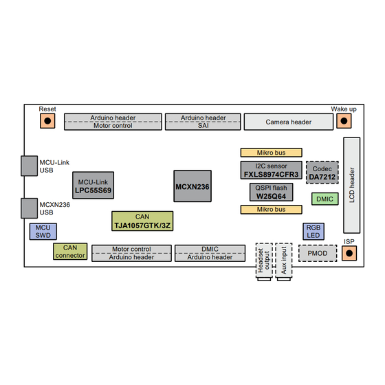
MCU-Link LPC55S69 Figure 2. FRDM-MCXN236 top view Figure 3 shows the top-side view of the FRDM-MCXN236 board, with connectors and push buttons highlighted. UM12041 All information provided in this document is subject to legal disclaimers. © 2024 NXP B.V. All rights reserved. - Page 5 UM12041 NXP Semiconductors FRDM-MCXN236 Board User Manual Figure 3. FRDM-MCXN236 connectors and push buttons (top-side view) Figure 4 shows the jumpers and LEDs on the FRDM-MCXN236 board. JP3 (DNP) JP4 (DNP) JP2 (DNP) JP1 (DNP) JP7 JP6 D6 D7 D8 Figure 4. FRDM-MCXN236 jumpers and LEDs UM12041 All information provided in this document is subject to legal disclaimers.
-
Page 6: Connectors
FRDM-MCXN236 Board User Manual Figure 5 shows the bottom view of the FRDM-MCXN236 board. Figure 5. FRDM-MCXN236 bottom view 1.5 Connectors Table 2 describes the FRDM-MCXN236 connectors. The connectors are shown in Figure Table 2. FRDM-MCXN236 connectors Part Connector type Description Reference section... -
Page 7: Jumpers
• Shorted (default setting): MCU-Link SWD clock is schematic enabled. 1.7 Push buttons Push buttons are populated on the FRDM-MCXN236 board for human machine interaction (HMI). Table 4 describes the FRDM-MCXN236 push buttons. The push buttons are shown in Figure UM12041 All information provided in this document is subject to legal disclaimers. -
Page 8: Leds
MCU-Link-specific LEDs, which are described in Section 3.10. The LEDs are shown in Figure Note: The FRDM-MCXN236 board also has three status indicator LEDs for MCU-Link. For details, see Section 3.10. UM12041 All information provided in this document is subject to legal disclaimers. -
Page 9: Frdm-Mcxn236 Functional Description
Reference Manual. 2.1 Power supplies The FRDM-MCXN236 board is powered with a P5V0 (5 V) power supply. The power source of P5V0 is SYS_5V0, which is powered using one of the following source options: • P5V_USB_HS supply from high-speed (HS) USB2.0 Type-C connector (J11) •... - Page 10 1 µF UM1550S-18 0 Ω AGND MCU_ANALOG_POW AGND Figure 8. FRDM-MCXN236 system power circuit diagram 5 V power sources and selection Table 6 describes the 5 V input power sources and their output power supplies. Table 6. 5 V power sources Part identifier...
- Page 11 UM12041 NXP Semiconductors FRDM-MCXN236 Board User Manual Table 6. 5 V power sources ...continued Part identifier Device / power source Output power supply Description • TJA1057 CAN PHY (U11) and CAN 2x2-pin header (J13) • mikroBUS connector (J5) • HS USB connector power switch NX5P3090 UK (U4) The J3 pin 10 is the onboard 5 V output by default, and can also be used as an external 5 V input option.
-
Page 12: Power Supply Configuration
UM12041 NXP Semiconductors FRDM-MCXN236 Board User Manual Table 8. 1V8 power supply Part identifier Device / power source Output power supply Description UM1550S-18 (Union VDD_1V8 Power supply for the Audio codec (U6) Semiconductors) 2.1.1 Power supply configuration Once the main power configurations are set, the target MCU power configurations must be made. The MCU... -
Page 13: Dc-Dc Inductor
Choosing the right DC-DC inductor for your target board is important. When selecting a DC-DC inductor, refer to the specifications mentioned in the MCX N23x Product Family Data Sheet. 2.2 Clocks The FRDM-MCXN236 board provides crystal oscillators to provide accurate time bases for the device and different components on the board. Table 11 describes the clock sources available on the FRDM-MCXN236 board. -
Page 14: Usb Interface
2.3 USB interface The target MCU (MCXN236) features one high-speed USB module with device and host capabilities and a built- in transceiver. On the FRDM-MCXN236 board, the HS USB controller and PHY interface connected to the USB Type-C connector (J11). Figure 10 shows the high-speed USB circuit diagram. - Page 15 PORT=0: UFP mode – When floating (default setting): DRP mode On the FRDM-MCXN236 board, the MCU_USB1_DP and MCU_USB1_DM signals from the target MCU connect to the onboard USB connector (J11) directly through a common mode choke. The common mode choke is included for noise suppression on the DM / DP signals.
-
Page 16: Flexcan Interface
The target MCU (MCXN236) supports two CAN (w/ wo FD) controllers (CAN0 and CAN1). On FRDM-MCXN236, only the CAN1 controller is used. The CAN1 controller connects to a 4-pin CAN header through a CAN transceiver (TJA1057GTK/3Z). The CAN1_TXD and CAN1_RXD signals are through ports P4_16 and P4_15, respectively. -
Page 17: Accelerometer Sensor Interface
CAN1_L CAN transceiver low signal 2.5 Accelerometer sensor interface On the FRDM-MCXN236 board, an accelerometer sensor is used to sense motion, a feature required in the IoT application space. The main features of the Accelerometer sensor interface are as follows. -
Page 18: Flash Memory Interface
2.6 Flash memory interface On the FRDM-MCXN236 board, one serial flash memory is provided. The flash memory VCC pin is supplied by the VDD_BOARD rail. The QSPI data and clock signals for the flash memory interface are available on Port P3_[12:13] and P3_[20:23] pins. -
Page 19: Visible Light Sensor Interface
The MCXN236 device features two instances of the SAI module, SAI0 and SAI1. The FRDM-MCXN236 board features an audio codec DA7212 (DNP), which connects to the SAI1 module of the target MCU. By default, the SAI1 receive and transmit signals from the MCXN236 MCU connect to the onboard audio codec through Port P3 and P2 pins. -
Page 20: Arduino Compatible I/O Headers
54-00174 Headphone jack 2.9 Arduino compatible I/O headers The FRDM-MCXN236 board provides Arduino Uno compatible headers to support the Arduino and FRDM ecosystem shield modules. These headers are dual-row headers with the outer rows supporting the Arduino UM12041 All information provided in this document is subject to legal disclaimers. - Page 21 UM12041 NXP Semiconductors FRDM-MCXN236 Board User Manual compatible shields and the inner rows supporting the various FRDM shields. These headers are designed to support the following shields: • Sensor: FRDM-STBC-AGM01, FRDM-STBC-AGM04, FRDM-FXS-MULT2-B • NFC: OM5577, OM5578 • USB Type C: OM13790 (Host) •...
- Page 22 UM12041 NXP Semiconductors FRDM-MCXN236 Board User Manual Table 19. Arduino compatible header J1 pinout Device Function / Signal name Resistor setting Potential conflict number pin / GPIO P3_16 SAI1_TX_BCLK • Arduino connector J2 pin 10 (P3_16/PWM1_A2-ARD_D11 through SJ2 resistor pin 2-3 selection (DNP by default)) •...
- Page 23 UM12041 NXP Semiconductors FRDM-MCXN236 Board User Manual Table 19. Arduino compatible header J1 pinout ...continued Device Function / Signal name Resistor setting Potential conflict number pin / GPIO P2_9 SAI1_RXD0 P0_22 ARD_D7 • Arduino connector J2 pin 9 (P0_ 22/CMP1_IN2-MC_CUR_DCB) Table 20. Arduino compatible header J2 pinout...
- Page 24 UM12041 NXP Semiconductors FRDM-MCXN236 Board User Manual Table 20. Arduino compatible header J2 pinout ...continued Device Function / Signal name Resistor setting Potential conflict number pin / GPIO VDDA_MCU P0_24 GPIO • I2C sensor (U10) pin 6 (P0_24/ ACCL_INT2) • FlexIO header J8 pin 8 (P0_24/ FXIO_LCD_DC) •...
- Page 25 UM12041 NXP Semiconductors FRDM-MCXN236 Board User Manual Table 21. Arduino compatible header J3 pinout ...continued Device pin / Function / Signal name Resistor setting Potential conflict number GPIO P2_7 PWM1_B0 • Arduino connector J1 pin 12 (P2_7/PWM1_B0-ARD_D5) • QSPI Flash memory U12 (P3_...
-
Page 26: Flexio Header
ARD_A5 • Arduino header J1 pin 1 (P4_ 13/TRIG_IN8-MC_ENC_B) 2.10 FlexIO header On the FRDM-MCXN236 board, one 28-pin FlexIO header (J8) is provided to support the LCD display and camera applications. Table 23 describes the pinout of the FlexIO header. -
Page 27: Mikrobus Headers
UM12041 NXP Semiconductors FRDM-MCXN236 Board User Manual Table 23. FlexIO header J8 pinout ...continued GPIO Function / Signal name Description Potential conflict number P0_14 FXIO_D6 FXIO D6 P0_15 FXIO_D7 FXIO D7 P3_0 FXIO_D8 FXIO_D8 P3_1 FXIO_D9 FXIO_D9 P3_2 FXIO_D10 FXIO_D10 P2_3... -
Page 28: Camera Header
The FRDM-MCXN236 provides a header for the camera connection. This is to demonstrate the camera interface features of the MCXN236 device. Note: The FRDM-MCXN236 board is tested with the OV7670 camera. Only pin 7- pin 22 are necessary for the OV7670 camera. - Page 29 UM12041 NXP Semiconductors FRDM-MCXN236 Board User Manual Table 26. Camera header connections GPIO Function Resistor setting Potential conflict number P1_15 SmartDMA_PIO11 P1_14 SmartDMA_PIO10 P1_17 SmartDMA_PIO13 • Arduino header J2 pin 20 (P1_ 17/FC5_I2C_SCL-ARD_D19) • mikroBUS header J6 pin 3 (P1_ P1_16...
-
Page 30: Board Operating Conditions
GPIO 2.13 Board operating conditions The operating temperature range for the FRDM-MCXN236 board is -40 ℃ to +105 ℃. The MCXN23x device supports up to 125 ℃ junction temperature. See MCX N23x Product Family Data Sheet for more details on device operating conditions. -
Page 31: Supported Debug Scenarios
J-Link firmware does not support this feature. 3.3 Supported debug scenarios In the FRDM-MCXN236 board, the MCU-Link debug probe target can be either the MCXN236 MCU or an external target compliant with MCU-Link. The board also allows to use an external debugger for debugging the MCXN236 MCU, in place of the MCU-Link debug probe. -
Page 32: Updating Mcu-Link Firmware Using The Firmware Utility
UM12041 NXP Semiconductors FRDM-MCXN236 Board User Manual with support for many NXP debug probes. You are recommended to use the LinkServer installer unless you are using MCUXpresso IDE version 11.6.1 or earlier. For details on this utility, refer https://nxp.com/linkserver. Note: If the firmware version of the onboard MCU-Link probe is 3.122 or later, LinkServer version 1.4.85 or later provides the support of automatic firmware update. -
Page 33: Using Mcu-Link With Development Tools
CMSIS-DAP probes or J-Link probes (depending on the firmware image you are using.) 3.7 MCU-Link USB connector The FRDM-MCXN236 board has a USB 2.0 Type-C connector J10. This USB connector is used to create MCU-Link high-speed USB connection with the host computer. The MCU-Link receives power when the USB connector J10 is plugged into a USB host. -
Page 34: Connecting To A Target Through A Usb-To-Spi Or Usb-To-I2C Bridge
NXP for Windows/Linux/MacOS systems. For more details on the libusbsio library, see https://www.nxp.com/libusbsio. In the FRDM-MCXN236 board, MCU-Link connects to the P1_[3:0] pins of the target MCU using the FC3 SPI interface connection through zero-ohm resistors. By default, these resistors are populated and enable the communication between MCU-Link and the target MCU through the USB-to-SPI bridge. -
Page 35: Board Errata
FRDM-MCXN236 board. Some of the documents listed below may be available only under a non-disclosure agreement (NDA). To request access to these documents, contact your local field applications engineer (FAE) or sales representative. -
Page 36: Revision History
UM12041 NXP Semiconductors FRDM-MCXN236 Board User Manual Table 32. Acronyms ...continued Term Description Pulse width modulation QSPI Quadruple serial peripheral interface Real-time clock Serial peripheral interface Serial wire debug Serial wire debug trace output UART Universal asynchronous receiver/transmitter Universal serial bus... -
Page 37: Legal Information
NXP Semiconductors. In the event that customer uses the product for design-in and use in In no event shall NXP Semiconductors be liable for any indirect, incidental, automotive applications to automotive specifications and standards, punitive, special or consequential damages (including - without limitation - customer (a) shall use the product without NXP Semiconductors’... - Page 38 UM12041 NXP Semiconductors FRDM-MCXN236 Board User Manual AMBA, Arm, Arm7, Arm7TDMI, Arm9, Arm11, Artisan, big.LITTLE, Bluetooth — the Bluetooth wordmark and logos are registered trademarks Cordio, CoreLink, CoreSight, Cortex, DesignStart, DynamIQ, Jazelle, owned by Bluetooth SIG, Inc. and any use of such marks by NXP Keil, Mali, Mbed, Mbed Enabled, NEON, POP, RealView, SecurCore, Semiconductors is under license.
-
Page 39: Table Of Contents
Board kit contents ..........4 Board pictures ........... 4 Connectors ............6 Jumpers ............. 7 Push buttons ............7 LEDs ..............8 FRDM-MCXN236 functional description ..9 Power supplies ..........9 2.1.1 Power supply configuration ......12 2.1.2 DC-DC inductor ..........13 Clocks .............. 13 USB interface ..........
Need help?
Do you have a question about the FRDM-MCXN236 and is the answer not in the manual?
Questions and answers