Advertisement
Quick Links
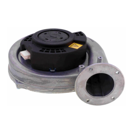
Challenger Blower
Replacement Kit
Kit Part Numbers:
• CCRKIT32: Challenger Blower Kit
Kit Includes:
1. Blower
2. Blower Outlet Gasket
3. (2) M5 Flange Nuts
4. Gas Pipe O-ring
5. Venturi Clip
Recommended Tools:
• Phillips screwdriver
• 8 mm socket and/or 8 mm wrench
• Adjustable wrench
• Pliers
• Flat putty knife
• Combustion Analyzer
WARNING
!
Indicates a potentially hazardous situation which,
if ignored, can result in substantial property dam-
age, serious injury, or death .
WARNING
!
For your safety, turn off electrical power supply at
service panel before proceeding to avoid possible
electrical shock hazard. Failure to do so can cause
severe personal injury or death.
WARNING
!
For your safety, the boiler may be extremely hot.
Ensure the boiler has properly cooled prior to ser-
vicing. Failure to do so can cause severe personal
injury.
NOTICE
Indicates special instructions on installation, operation
or maintenance, which are important to equipment
but not related to personal injury hazards.
WARNING
!
Failure to follow instructions below can result in
severe personal injury or damage if ignored.
•
Instructions are for a qualified installer/ ser-
vice technician only.
•
Read all instructions before proceeding.
•
Follow instructions in proper order.
1
Advertisement

Related Manuals for TriangleTube CCRKIT32


Summary of Contents for TriangleTube CCRKIT32
- Page 1 Challenger Blower Replacement Kit Kit Part Numbers: • CCRKIT32: Challenger Blower Kit Kit Includes: 1. Blower 2. Blower Outlet Gasket 3. (2) M5 Flange Nuts 4. Gas Pipe O-ring 5. Venturi Clip Recommended Tools: • Phillips screwdriver • 8 mm socket and/or 8 mm wrench •...
- Page 2 Challenger Blower Replacement Kit 1. Removal of Blower 1. Turn off power to the unit at the main service switch. 2. Close the external gas shut off valve to the appli- ance. 3. Remove the front panel by flipping down the dis- play cover and loosening the (2) Phillips head screws at the control panel as per Fig.
- Page 3 Challenger Blower Replacement Kit 2. Installation of Blower NOTICE 1. Prior to reassembling the gas pipe and venturi into Do not discard the blower orifice as it will be reused. the new blower, replace the gas pipe o-ring at the end of the gas pipe.
- Page 4 Challenger Blower Replacement Kit 6. With the gas orifice in place, reconnect the gas pipe display shows “h” or twice until the operating dis- brass nut to the gas valve. See Fig. 2. play shows “H” for high fire. 7. If previously removed, reinstall the vent pipe. Perform the following procedure to manually place the burner into low fire.
Need help?
Do you have a question about the CCRKIT32 and is the answer not in the manual?
Questions and answers