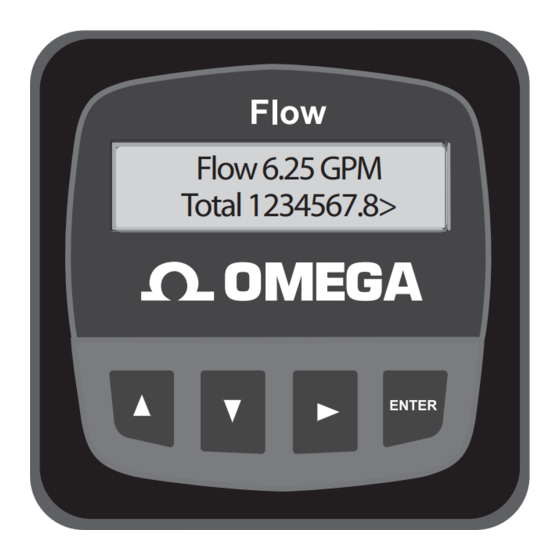
Summary of Contents for Omega FP90 Series
- Page 1 User’ s Gui d e Flow 6.25 GPM Total 1234567.8> Shop online at www.omega.com e-mail: info@omega.com ISO9002 ISO9001 CERTIFIED CERTIFIED CORPORATE QUALITY CORPORATE QUALITY STAMFORD, CT MANCHESTER, UK FP90 SERIES Flow Transmitters...
- Page 2 Toll Free in United Kingdom: 0800-488-48 e-mail: sales@omega.co.uk It is the policy of OMEGA to comply with all worldwide safety and EMC/EMI regulations that apply. OMEGA is constantly pursuing certifi cation of its products to the European New Approach Directives.
-
Page 3: Installation
4. Menu Functions Installation FP90 series transmitters are available in two styles: panel mount and ¿ eld mount. The panel mount is supplied with the necessary hardware to install the transmitter. This manual includes complete panel mounting instructions. Field mounting requires one of two separate mounting kits. The FP90IM integral kit joins the sensor and instrument together into a single package. -
Page 4: Electrical Connections
Snsr 2 V+ FP-5300 (BLACK) FP-8501A FP-6000 Snsr 1 Gnd (SHIELD) FP-2541 FP-8500 Snsr 1 IN FMG-3000 Series Magmeter (RED) FP-8501 FMG-550 Series magmeter Snsr 1 V+ (BLACK) Any Open Collector pulse input page 2 OMEGA FP90 Series Flow Transmitter Instructions... - Page 5 AUX Power + AUX Power + * See AUX POWER Note Power Supply 12-24 VDC Auxiliary Power note: AUXILIARY power is used only if the flow sensor requires more than 1.5 mA current. OMEGA FP90 Series Flow Transmitter Instructions page 3...
- Page 6 AUX Power - AUX Power + AUX Power + Power * See AUX POWER Note Supply 12-24 VDC Auxiliary Power note: • AUXILIARY Power is required for all systems where relays are used. page 4 OMEGA FP90 Series Flow Transmitter Instructions...
- Page 7 AUX Power + AUX Power + P ower – S upply 12–24 V DC Auxiliary Power Note: Auxiliary power is necessary for flow sensors that require more than 1.5 mA of current. OMEGA FP90 Series Flow Transmitter Instructions page 5...
-
Page 8: View Menus
All of the displays below are temporary. After ten minutes the display will return to the permanent display. Perm: 12345678 Monitor the Permanent Totalizer value. Gallons Loop Output: Monitor the 4-20 mA Loop output. 12.00 mA Last CAL: Monitor date for scheduled maintenance or date of last calibration. 6-16-09 page 6 OMEGA FP90 Series Flow Transmitter Instructions... - Page 9 Monitor the 4-20 mA Loop 1 output. 12.00 mA Loop 2 Output: Monitor the 4-20 mA Loop 2 output. 12.00 mA Last CAL Monitor date for scheduled maintenance or date of last calibration. 6-16-09 OMEGA FP90 Series Flow Transmitter Instructions page 7...
- Page 10 Press the UP and DOWN keys simultaneously while Output Setpnt: Saving any element is À ashing. This will recall the last saved value of the item being edited and return you Output Setpnt: to Step 3. 19.00 GPM > page 8 OMEGA FP90 Series Flow Transmitter Instructions...
- Page 11 The FP90 allows any value from ÷1 to ÷254. Divide by 1 > Use this “note pad” to record important dates, such as annual recerti¿ cation or scheduled maintenance. Last CAL: 6-16-09 OMEGA FP90 Series Flow Transmitter Instructions page 9...
- Page 12 Press UP and DOWN keys to manually order any output current value from 3.6 mA to Test Loop: 21.00 mA to test the output loop. > Press UP and DOWN keys to manually toggle the Open Collector output state. Test Output: > page 10 OMEGA FP90 Series Flow Transmitter Instructions...
- Page 13 999.9 seconds. 0.1 Seconds > Last CAL: Use this “note pad” to record important dates, such as annual recerti¿ cation or scheduled maintenance. 6-16-09 All Relay settings repeat for Relay 2. OMEGA FP90 Series Flow Transmitter Instructions page 11...
- Page 14 Press UP and DOWN keys to manually order any output current value from 3.6 mA to Test Loop: 21.00 mA to test the output loop. > Press UP and DOWN keys to manually toggle the state of relay 1. Test Relay 1: Repeat for relay 2. > page 12 OMEGA FP90 Series Flow Transmitter Instructions...
- Page 15 Divide by 1 > Last Cal Use this “notepad” to record important dates, such as annual recerti¿ cation or scheduled maintenance. 6-16-09 > All functions labeled "1" will repeat for channel 2. OMEGA FP90 Series Flow Transmitter Instructions page 13...
- Page 16 21.00 mA to test current loop output #1. > Press UP or DOWN keys to manually toggle the state of open collector output #1. Test Output 1: > All functions labeled "1" will repeat for channel 2. page 14 OMEGA FP90 Series Flow Transmitter Instructions...
- Page 17 “Value must be more than 0” K-factors cannot be set to 0. • Enter K-factor between 0.0001 to 99999 Relay or open Collector output Hysteresis value too large • Reset the hysteresis value is always activated OMEGA FP90 Series Flow Transmitter Instructions page 15...
- Page 18 Notes: page 16 OMEGA FP90 Series Flow Transmitter Instructions...
- Page 19 CONDITIONS: Equipment sold by OMEGA is not intended to be used, nor shall it be used: (1) as a “Basic Component” under 10 CFR 21 (NRC), used in or with any nuclear installation or activity; or (2) in medical applications or used on humans.
- Page 20 Where Do I Find Everything I Need for Process Measurement and Control? OMEGA…Of Course! Shop online at www.omega.com TEMPERATURE • Thermocouple, RTD & Thermistor Probes, Connectors, Panels & Assemblies • Wire: Thermocouple, RTD & Thermistor • Calibrators & Ice Point References •...


Need help?
Do you have a question about the FP90 Series and is the answer not in the manual?
Questions and answers