Sign In
Upload
Download
Table of Contents
Contents
Add to my manuals
Delete from my manuals
Share
URL of this page:
HTML Link:
Bookmark this page
Add
Manual will be automatically added to "My Manuals"
Print this page
×
Bookmark added
×
Added to my manuals
Manuals
Brands
oxycom Manuals
Fan
IntrCooll Std.
Manual
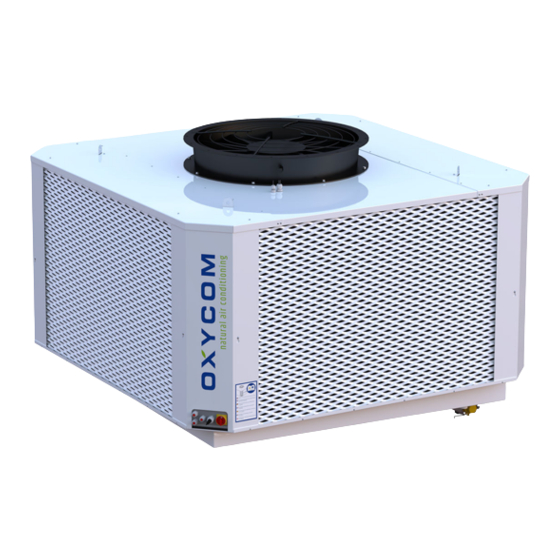
oxycom IntrCooll Std. Manual
Direct / indirect evaporative cooler
Hide thumbs
1
2
3
4
5
6
7
8
9
10
11
12
13
14
15
16
17
18
19
20
21
22
23
24
25
26
27
28
29
30
31
32
33
34
35
36
37
38
39
40
41
42
43
44
45
46
47
48
49
50
51
52
53
54
55
56
57
58
59
60
61
62
63
64
65
66
67
68
page
of
68
Go
/
68
Contents
Table of Contents
Bookmarks
Table of Contents
Table of Contents
Preface
Warranty
Product Liability
Compliance
Contact Data
About this Manual
Scope of this Manual
Audience
Typographical Conventions
Availability
Related Documents
General (Safety)
Safety
Handling and Storage
Arrival of the Package
Preparations
Handling and Storage
Transport
Prepare the Location
Location Requirements
Support Frame (Not Provided)
Ducting
Natural Ventilator
Flashing Kit Intrcooll® (Optional)
Ducting
Opening and Curb
Roof Beam Supports
Roof Transit for Ducting
Roof Transits for Cabling / Plumbing
Supply Air Ducting
Exhaust Air
Water Requirements
Drain Connection Requirements
Overflow Connection Requirements
Water Connections
Electrical Requirements
Communication Requirements
Preparations
Install the Intrcooll
Step 1. Positioning and Leveling
Step 2. Duct Connection to the Intrcooll
Step 3. Drain Valve Installation
Step 4. Flow Regulator Cap
Step 5. Making Connections
Step 6. Check Installation and Settings
Step 7. Finish the Installation
Install the Intrcooll®
How to Operate the Intrcooll
Operation Procedures
System Status and Settings
Update Firmware
Appendices
Advertisement
Quick Links
1
Communication Requirements
2
Step 6. Check Installation and Settings
3
How to Operate the Intrcooll
4
Operation Procedures
5
Appendices
Download this manual
IntrCooll Std. / Plus
Direct / Indirect evaporative cooler
Version: Version 1.3
Date: 14/12/2021
Manual
Installation
Table of
Contents
Previous
Page
Next
Page
1
2
3
4
5
Advertisement
Chapters
Table of Contents
3
Install the Intrcooll®
49
Table of Contents
Need help?
Do you have a question about the IntrCooll Std. and is the answer not in the manual?
Ask a question
Questions and answers
Related Manuals for oxycom IntrCooll Std.
Fan oxycom IntrCooll Plus Manual
Direct / indirect evaporative cooler (68 pages)
This manual is also suitable for:
Intrcooll plus
3800oxystd
380oxyplus
Table of Contents
Save PDF
Print
Rename the bookmark
Delete bookmark?
Delete from my manuals?
Login
Sign In
OR
Sign in with Facebook
Sign in with Google
Upload manual
Upload from disk
Upload from URL


Need help?
Do you have a question about the IntrCooll Std. and is the answer not in the manual?
Questions and answers