Table of Contents
Advertisement
Quick Links
Advertisement
Table of Contents

Summary of Contents for advidia M-400-P
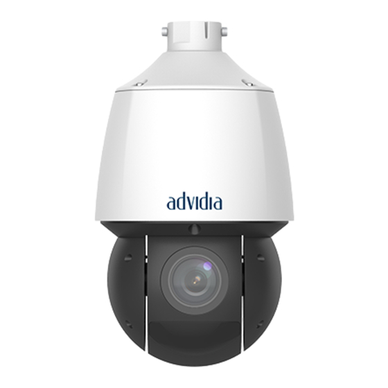
- Page 1 M-400-P Outdoor Network PTZ Dome Cameras Quick Guide V1.00...
-
Page 2: Table Of Contents
Contents Waterproof Requirements·································································································· 1 1 Packing List ······················································································································ 3 2 Safety and Compliance information ················································································ 3 2.1 Installation ··········································································································· 3 2.2 Maintenance········································································································ 3 2.3 Laser Safety (if applicable) ··················································································· 3 3 Appearance ····················································································································· 4 3.1 Dimensions ·········································································································· 4 3.2 Cable Connection ································································································· 6 4 Installation ·······················································································································... -
Page 3: Waterproof Requirements
Waterproof Requirements Please waterproof cables in accordance with the following instructions. User shall assume all responsibility for device damage caused by water due to improper waterproof measures. NOTE! Before you start, connect all the needed cables and cut off the copper wires for ... - Page 4 CAUTION! The cable connector must not be exposed and must be kept away from water. Restore and fasten the device after dismounting. Place the power adapter in a power distribution box. ...
-
Page 5: Packing List
Packing List Contact your local dealer if the package is damaged or incomplete. The components may vary with device model. Name Unit Camera Power adapter User manual Cable unit Cable unit sun shield ESD-preventive glove Bracket adapter ring Waterproof components Remarks: * means optional and supplied with certain models only. -
Page 6: Appearance
Never view lasers without protective eyewear. Some lasers emit infrared or ultraviolet, which are invisible to human eyes. Keep flammable or explosive objects away from laser beam. Some lasers may ignite combustible materials and thus cause fire. Never direct laser at a person. -
Page 7: Installation
ALARM GND Ground for Alarm (Black Cable) ALM OUT+ Alarm Output (Positive) (Orange/White Cable) ALM OUT- Alarm Output (Negative) (Orange Cable) RS485 D+ Serial port. (Positive) Connect external devices for communication, for example, to control third-party devices. (Yellow/Black Cable) RS485 D- Serial port. -
Page 8: Process Map
Process Map Installation Preparation Insert Micro SD card? Insert Micro SD card Mount SFP optical module? Mount SFP optical module Meet requirements? Install camera Check installation Preparation Installation position The bearing capacity of installation position shall meet requirements. Reinforce the installation position if necessary. Lightning protection and grounding requirements Select proper lightning protection devices for the power supply, audio and video cables, and RS485 cables. -
Page 9: Wall Mount
Remove the 4 screws on the back cover. Insert the micro SD card into the slot [For Model: M-400-P, SD card slot is positioned at slot 2 (Ref. below picture)]. Check that the sealing ring is in position. Put the back cover back in place, and turn the screws until they are fully tightened. -
Page 10: Startup
5. Secure the dome with two M5 screws. 6. Connect the cables and attach the bracket to the wall with flat washers, spring washers and nuts. screw Caution: Tighten the M5 screws to the extent that they make contact with the metal tube. - Page 11 If you are using Windows 7, you also need to save the setup.exe to your computer first, and then right-click the file and select Run as administrator. No live video after my first login? Answer: Please turn off the firewall on your computer and then log in again. How to restore factory default settings? Answer: Perform the following operations in 10 minutes after the camera is powered on: (1) Remove the back cover...
-
Page 12: Disclaimer And Safety Warnings
Disclaimer and Safety Warnings Copyright Statement No part of this manual may be copied, reproduced, translated or distributed in any form by any means without prior content in writing from our company (referred to as us hereafter). The product described in this manual may contain proprietary software owned by our company and its possible licensors. Unless permitted, no one is allowed to copy, distribute, modify, abstract, decompile, disassemble, decrypt, reverse engineer, rent, transfer, or sublicense the software in any form by any means. - Page 13 Add appropriate email address information in each user configuration. The address is used when you click “Forgot password”. Keep firmware up to date: It is recommended that your device is always upgraded to the latest version for the latest functions and better security.
- Page 14 © i-PRO Co., Ltd. All Rights Reserved. i-PRO, Viewnetcam.com, advidia, VideoInsight, CloUDE, and Unified Digital Evidence are registered trademarks or trademarks of i-PRO Co., Ltd. or i-PRO Americas Inc. in various jurisdictions. All other trademarks are the property of their respective owners.


Need help?
Do you have a question about the M-400-P and is the answer not in the manual?
Questions and answers