
Related Manuals for Emerson Rosemount Ultrasonic 3810 Series


Summary of Contents for Emerson Rosemount Ultrasonic 3810 Series
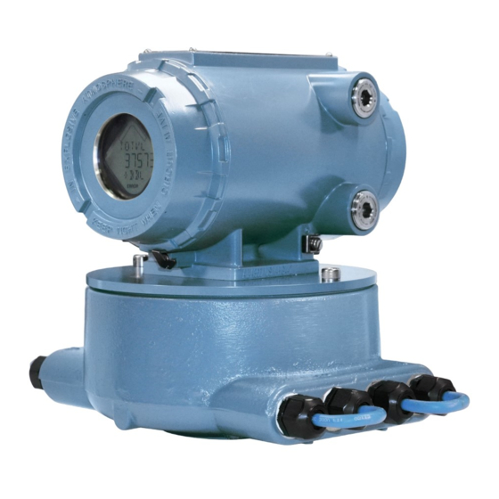
- Page 1 Upgrade kit instructions 00825-0200-3810, Rev AA June 2022 ™ Rosemount Ultrasonic 3810 Series Electronics...
-
Page 2: Table Of Contents
Upgrade kit instructions June 2022 Signal words and symbols Pay special attention to the following signal words, safety alert symbols, and statements: Safety alert symbol This is a safety alert symbol. It is used to alert you to potential physical injury hazards. Obey all safety messages that follow this symbol to avoid possible injury or death. -
Page 3: Plan
June 2022 Upgrade kit instructions Plan Introduction 1.1.1 General Welcome to the Rosemount 3810 Series Ultrasonic Instruction Manual. This manual has been designed to provide you with a step-by-step set of instructions for a Rosemount Liquid Ultrasonic meter with 3800 Series electronics to the new 3810 Series electronics. - Page 4 3810 Series electronics. Always ™ use the latest version of MeterLink . Upgrades to the latest version are available at: Emerson.com/Rosemount 3810 Series Electronics Upgrade kit instructions...
- Page 5 June 2022 Upgrade kit instructions Before removing the 3800 Series Electronics 1.3.1 Procedure before removing the 3800 Series Electronics Procedure 1. Before removing power from the meter being software to connect to the meter. ™ 2. Use the screen in MeterLink Edit/Compare Configuration to read the configuration from the meter and save it to a file on your computer.
- Page 6 Upgrade kit instructions June 2022 Figure 1-2: Accessing Modbus ID for Ports A and B 4. Based on the information contained in the connection properties window, enter the values for the following parameters in the Summary table of communications/output settings Appendix Port A and B: Modbus ID = _____(enter Comms Address).
- Page 7 June 2022 Upgrade kit instructions Figure 1-3: Remove End Caps from the Upper Electronics Enclosure Figure 1-4: 3800 Series Electronics Assembly board layout 8. Remove the 3800 Series electronics CPU board, the HART Option Board, and the Field Termination Board from the enclosure. Fill out Summary table of communications/output settings Appendix based on the Field Connection Board wire terminations and/or...
- Page 8 Upgrade kit instructions June 2022 Figure 1-5: 3800 Series CPU Board Showing Switch Settings Figure 1-6: 3800 Series CPU Board with I.S. Barrier Board Piggy- Backed on CPU Board 3810 Series Electronics Upgrade kit instructions...
- Page 9 June 2022 Upgrade kit instructions Removing 3800 Series Electronics 1.4.1 Procedure to remove the 3800 Series Electronics Procedure 1. Having obtained all the information related to the set-up of the 3800 Series electronics configuration and communications, all the components related to the electronics can now be physically removed from the meter.
- Page 10 Upgrade kit instructions June 2022 Figure 1-8: Remove Bolts from Base Enclosure Cover 5. Remove the upper electronics housing from the base enclosure. a) Remove the Acquisition cable, which comes down from the upper electronics to the Acquisition module in the base enclosure.
- Page 11 June 2022 Upgrade kit instructions Figure 1-9: Remove the Acquisition Cable 6. Remove all the screws that hold the transducer wires in the terminal blocks that attach the transducers to the Acquisition module. a) Remove the screws from the ends of the two connectors. b) Disconnect the connectors and remove each of the transducer wires from the connector.
- Page 12 Upgrade kit instructions June 2022 Figure 1-10: Remove Old RTV 10. Remove the base enclosure from the meter body. 11. If RTV silicone adhesive/sealant was used to seal the base enclosure to the meter body, remove the adhesive/sealant so the 3810 base enclosure will have a clean mounting surface.
-
Page 13: Install
June 2022 Upgrade kit instructions Install Installing the 3810 Series Electronics 2.1.1 Procedure to install the 3810 Series Electronics Procedure 1. Remove the 3810 Upgrade components from the packaging. a) Use the 6 mm Allen wrench to remove the two screws from the base enclosure cover. - Page 14 Upgrade kit instructions June 2022 must be oriented outward (towards the sides of the meter body, perpendicular to meter axis). Figure 2-2: Base Enclosure Orientation 6. Use the four ¼-in. bolts with stainless steel washers and nylon shoulder washers to secure the base enclosure to the meter body. a) Use a nut driver to tighten the bolts to a torque of 55 to 65 inch-lbs.
- Page 15 June 2022 Upgrade kit instructions Figure 2-4: Apply RTV Sealant Around Bolts 8. Insert the Acquisition board in the base enclosure and secure it with the two screws as shown for now. Figure 2-5: Acquisition Module Attachment Screws Upgrade kit instructions...
- Page 16 Upgrade kit instructions June 2022 Figure 2-6: Acquisition Module Wiring 9. Route the transducer cables through the cable glands with the correct label number (i.e. A1) which matches the label on the transducer cable. Figure 2-7: Base Enclosure Cable Glands Installation 10.
- Page 17 June 2022 Upgrade kit instructions Figure 2-8: Transducer Cable Cut Instructions 12. Insert tubing over wires, inner insulation and under shield approximately 1.5-in. of shield should overlap. 13. Insert and secure transducer cables through cable glands verify Line Mark is as referenced in Figure 2-7.
- Page 18 Upgrade kit instructions June 2022 Figure 2-10: Install Cable and Secure Wires 17. Use the cable ties to dress the transducer cables. They should be dressed in groups of two: A1 and C1, D1 and B1, A2 and C2, D2 and B2.
- Page 19 June 2022 Upgrade kit instructions Figure 2-11: Re-oriented and Secured Transducer Cables 18. Reconnect the acquisition cable connector to the acquisition module and secure the cable connector by tightening the two screws. 19. Install the cable clamp on the Acquisition cable with the screw, lock washer, flat washer to secure the cable to the final mounting hole of the Acquisition module..
- Page 20 Upgrade kit instructions June 2022 Figure 2-12: Installing the Acquisition Cable and Module A. Acquisition cable connector B. Acquisition cable C. Cable clamp and screw 20. Wrap the excess cable around the Acquisition Module and place the electronics housing into position on the base enclosure. 21.
- Page 21 June 2022 Upgrade kit instructions Figure 2-13: Bolt the Upper Enclosure to Base Enclosure 24. Remove the end cap next to the conduit entries from the upper enclosure. Figure 2-14 shows the layout of the 3810 electronics. Upgrade kit instructions...
- Page 22 Upgrade kit instructions June 2022 Figure 2-14: 3810 Series Electronics Layout A. End cap B. CPU module C. Optional I/O module D. 3810 Series Transmitter electronics enclosure E. I. S. Barrier module F. Power supply G. Backplane H. Optional local display module I.
- Page 23 June 2022 Upgrade kit instructions L. Cable glands M. U.L. warning tag - Base enclosure N. M20 plug O. Gasket The following table shows the default communications and output settings for the 3810 electronics and configuration. Table 2-1: 3810 Series Default Communications and Output Settings Communication Default setting...
- Page 24 Upgrade kit instructions June 2022 25. Check the CPU module switches on the to ensure they are set properly. Figure 2-15: CPU Switch Settings A. WRITE PROT. switch B. DHCP switch C. Port A (override) The DHCP switch enables or disables the DHCP server for Ethernet communication.
- Page 25 June 2022 Upgrade kit instructions Figure 2-16: Install Wiring Terminal Block Connectors to the CPU Module All of the terminations in the 3810 Series electronics are removable terminal blocks. Removing the terminal blocks from the modules before terminating wires to them makes wiring easier. 3810 Communication and Output settings of this document also includes...
- Page 26 Upgrade kit instructions June 2022 Figure 2-17: Transmitter Electronics Enclosure Ground Wire 28. Attach flex conduit to the conduit ports on the transmitter electronics enclosure. Before applying power to the meter, ensure the atmosphere is proven safe using an intrinsically safe gas detector. WARNING EXPLOSION HAZARD Do not apply power to the meter with the end caps removed unless...
-
Page 27: Operate
June 2022 Upgrade kit instructions Operate Configure the 3810 Series Electronics 1. Check all settings and wiring carefully. 2. Set up the Meter Directory, and start initial communication with the 3810 Series electronics. The basic instructions for setting up the directory and initializing communications are contained in the following text. - Page 28 Upgrade kit instructions June 2022 a) Click the Edit Meter Directory button. b) Click the Add button (below the Meter Directory file operations field). MeterLink inserts the New Meter record in the last field in the Meter Directory table. 6. Create a new meter directory record with the following parameters: a) Enter a name for the meter.
- Page 29 June 2022 Upgrade kit instructions Figure 3-1: CPU RS-232 serial connection Table 3-1: CPU RS-232/RS-485 wire colors Wire colors White C O M Black ™ 3. Start MeterLink on the PC and create a new Meter Directory record with the following parameters: Upgrade kit instructions...
- Page 30 Upgrade kit instructions June 2022 a) Enter a name. b) Select Meter Type as Gas or Liquid as appropriate. c) Check the Direct box and uncheck the Modem and Ethernet boxes. d) Set the Direct connection properties for Baud Rate of 19200 and Comms Address (Modbus ID) of 32.
- Page 31 June 2022 Upgrade kit instructions Follow the instructions in LINK HERE to write the converted configuration file to the meter. Meter Communications Settings Procedure 1. Use the menu path to Meter|Communications Settings access the Communications dialog. This dialog displays the communications parameters for the 3810 Series electronics and is used to adjust the Baud Rate and Comms Address (i.e.
- Page 32 Upgrade kit instructions June 2022 Figure 3-3: Change driver selection for RS-485 half duplex or full duplex communication 3.1.3 Write the converted configuration file to the meter Important If the Mark III electronics contained keys, the user needs to ensure the same keys are enabled in the 3410 electronics prior to writing the convereted configuration.
- Page 33 June 2022 Upgrade kit instructions 2. Click Open and the dialog Open Configuration File displays. Figure 3-4: Edit/Compare Configuration Dialog a) Select the final 3800 Series configuration file created in Step 2 Procedure before removing the 3800 Series Electronics this document (i.e., “Meter Name, 3800 Series Final Config, 3-4-2005 10-15-02 AM.cfg”).
- Page 34 Upgrade kit instructions June 2022 Figure 3-6: Edit/Compare Configuration Dialog with Active Convert Button If the meter supports HART, check the 2nd variable parameter setting using the Field Setup Wizard| dialog. A reminder dialog prompts you Current Outputs to set this parameter. Figure 3-7: HART Parameter Settings For Liquid ultrasonic meters, the HART Secondary Variable option is:...
- Page 35 June 2022 Upgrade kit instructions Figure 3-8: Converted Configuration with Highlighted Changes d) Click Write Checked to write the converted configuration to ™ the meter (see Figure 3-8). If an error occurs, MeterLink will display a message indicating the nature of the problem. Manually edit the parameter(s) with errors to successfully complete the download.
- Page 36 Upgrade kit instructions June 2022 Figure 3-9: Meter Monitor Dialog 3.1.4 Configure the meter using the Field Setup Wizard Configuring the meter using the Field Setup Wizard Procedure 1. Use the menu path to access the Meter|Field Setup Wizard Field Setup Wizard Startup dialog. a) Verify that all settings (options) are correct (e.g., temperature, pressure, meter connections and meter outputs).
- Page 37 June 2022 Upgrade kit instructions Figure 3-10: Field Setup Wizard Startup Dialog 2. Setup the Frequency and Digital Output Sources parameters from the Field Setup Wizard Frequency/Digital Outputs Sources Page. Figure 3-11: Field Setup Wizard Frequency and Digital Output Sources Page Upgrade kit instructions...
- Page 38 Upgrade kit instructions June 2022 The meter has user-configurable selections for either a frequency output or digital status (FODO). Use the pull-down menus to edit these parameters. (3) Frequency/Digital Outputs: • FODO1 (four possible output configurations) • FODO2(eight possible output configurations) •...
- Page 39 June 2022 Upgrade kit instructions • 1000 Hz • 5000Hz 3. If changes were made in the Field Setup Wizard, choose to save the ™ configuration when MeterLink prompts you after the changes are written to the meter. Click Finish in the Field Setup Wizard dialog to write any changes to the meter.
-
Page 40: Mark Iii Wiring I/O And Switch Settings
Upgrade kit instructions June 2022 Mark III Wiring I/O and switch settings Use the wiring I/O and switch settings in this appendix to configure the 3810 Series electronics parameters. Figure A-1: Mark III Field Connection Board Switches and Connectors 3810 Series Electronics Upgrade kit instructions... - Page 41 June 2022 Upgrade kit instructions Figure A-2: Mark III CPU Boards Switches Note The switch positions shown in the sketches of the switch banks are the factory default positions. 3800 Series RS-232 Full Duplex Figure A-3: Port A Settings Upgrade kit instructions...
- Page 42 Upgrade kit instructions June 2022 Figure A-4: Port B Settings 3800 Series RS-485 Half Duplex Figure A-5: Port A Settings (Factory Default Switch Settings for Port A) Figure A-6: Port B Settings 3810 Series Electronics Upgrade kit instructions...
- Page 43 June 2022 Upgrade kit instructions 3800 Series Discrete output switch settings Figure A-7: Group 1 Frequency and Digital Outputs Figure A-8: Group 2 Frequency and Digital Outputs Upgrade kit instructions...
- Page 44 Upgrade kit instructions June 2022 Figure A-9: Series 100 Option Board (If Installed) 3800 Series RS-232 Full Duplex Figure A-10: Port C Settings 3800 Series RS-485 Half Duplex Figure A-11: Port C Settings 3810 Series Electronics Upgrade kit instructions...
- Page 45 June 2022 Upgrade kit instructions 3800 Series Series 100 option board (if installed) Figure A-12: Analog Output 1 Figure A-13: Analog Input 1 (Temperature) Figure A-14: Analog Input 2 (Pressure) Upgrade kit instructions...
- Page 46 Upgrade kit instructions June 2022 Figure A-15: Series 100 Plus HART Option Board (If Installed) 3800 Series RS-232 Full Duplex Figure A-16: Port C Settings 3800 Series RS-485 Half Duplex Figure A-17: Port C Settings 3810 Series Electronics Upgrade kit instructions...
- Page 47 June 2022 Upgrade kit instructions 3800 Series Series 100 plus HART option board (if installed) Figure A-18: Analog Output 1 Figure A-19: Analog Output 2 (HART capable) Figure A-20: Analog Input 1 (Temperature) Figure A-21: Analog Input 2 (Pressure) Upgrade kit instructions...
-
Page 48: Summary Table Of Communications/Output Settings
Upgrade kit instructions June 2022 Summary table of communications/output settings Based on switch position on the 3800 CPU board and Option board if installed, indicate the appropriate configuration for each communication/ output parameters on the 3800 electronics. Use these parameters to configure the 3810 Series electronics. - Page 49 June 2022 Upgrade kit instructions Table B-1: Communications/Output Settings Summary Table (continued) Output (Check electronics switch settings and circle appropriate box for type each output) Frequen TTL (if S8-4 is set Open Collector (if used (if to TTL) S8-4 is set to OC) output J5-1 not used)
- Page 50 Upgrade kit instructions June 2022 Table B-2: Communications/Output Settings Summary Table Results (continued) Output type Enter communications and output settings Serial port B Serial port C Digital output 1A Digital output 1B Frequency output 1A Digital output 2A Digital output 2B Frequency output 1B Frequency output 2A Frequency output 2B...
- Page 51 June 2022 Upgrade kit instructions Upgrade kit instructions...
-
Page 52: 3810 Communication And Output Settings
Upgrade kit instructions June 2022 3810 Communication and Output settings 3810 Wiring and I/O Refer to the 3810 Series Ultrasonic Liquid Flow Meter Installation Manual for more wiring details. Figure C-1: CPU Module Labeling and LED Indicators Table C-1: CPU Module Labeling and LED Functions CPU Module label or LED Function Switch position indicator... - Page 53 June 2022 Upgrade kit instructions Table C-1: CPU Module Labeling and LED Functions (continued) DHCP Dynamic Host Protocol Switch position Server - enables you to • ON - the meter is communicate with a enabled to act as a ™ Rosemount Ultrasonic DHCP server for a...
- Page 54 Upgrade kit instructions June 2022 Table C-1: CPU Module Labeling and LED Functions (continued) MEAS System color indicates LED status metrology mode • Red flashing LED Acquisition mode • Solid red the Acquisition Module is Measurement mode not communicating with the CPU Module •...
- Page 55 June 2022 Upgrade kit instructions NOTICE RESTRICTED ETHERNET AND SERIAL CONNECTIVITY USAGE Failure to restrict Ethernet and communication access to the 3810 Series Liquid Ultrasonic Flow Meter can result in, among other things, unauthorized access, system corruption, and/or data loss. User is responsible for ensuring that physical access and Ethernet or electronic access to the 3810 Series Liquid Ultrasonic Flow Meter is appropriately controlled and any necessary security precautions are...
- Page 56 Upgrade kit instructions June 2022 A DIN 41612 48-pin connector is the interface from the CPU Module to the Backplane (male end located on the back of the Backplane Board). Input and output connections The Rosemount 3810 Series Ultrasonic Flow Meter provides the Analog inputs for pressure and temperature, Analog output 2 and frequency and digital outputs on the CPU Module lower terminal block.
- Page 57 June 2022 Upgrade kit instructions Figure C-2: CPU Module Lower Terminal Block I/O Connections A. Frequency/Digital output 2 (FODO 2) B. Frequency/Digital output 2 (FODO 2) Gnd C. Frequency/Digital output 2 (FODO 2) Gnd D. Frequency/Digital output 3 (FODO 3) E.
- Page 58 Upgrade kit instructions June 2022 Figure C-3: Frequency/Digital Output Output for FODO1 and Digital Output1 (Group 1 on the CPU Module upper terminal block) share a common ground and have 50V isolation. FODO2 and FODO3 (Group 2 on the CPU Module lower terminal block) share a common ground and have 50V isolation.
- Page 59 June 2022 Upgrade kit instructions Figure C-4: CPU Module - Frequency/Digital Outputs Common Ground - Type 2 A. FODO1 and Digital input1 - shared common ground (Group1) B. FODO2 and FODO3 - shared common ground (Group2) Upgrade kit instructions...
- Page 60 Upgrade kit instructions June 2022 Figure C-5: CPU Module - Frequency/Digital Outputs Common Ground - Type 4 A. FODO1 and DI1/FODO6 - shared common ground - Type 4 CPU Module (Group 1) B. FODO2, FODO3, FODO4 and FODO5 - shared common ground - Type 4 CPU Module (Group 2) Serial communications ™...
- Page 61 June 2022 Upgrade kit instructions Port A supports a special override mode which forces the port to use known communication values (19200 baud, address 32, RS-232). Note that the protocol is auto-detected. This mode is expected to be used during meter commissioning (to establish initial communication) and in the event that the user cannot communicate with the meter (possibly due to an inadvertent communication configuration change).
- Page 62 Upgrade kit instructions June 2022 Table C-3: Serial Port Parameters (continued) Port/communication Description Common features Ethernet Preferred port for Modbus TCP/IP, Modbus diagnostic communication via MeterLink 10 Mbps/100 Mbps RS-485 2-wire connections use TX+ and TX - on the CPU Module Denotes auto-detected protocols Denotes auto-detected protocols Denotes auto-detected protocols...
- Page 63 June 2022 Upgrade kit instructions Analog output settings The Rosemount 3810 Series Ultrasonic Flow Meter provides two 4-20 mA analog output signals that are software configurable for either sink or source current. Refer to the System Wiring Diagram in Appendix ®...
- Page 64 Upgrade kit instructions June 2022 Figure C-7: CPU Module Power Source Connections A. 24V Loop power B. Power in connector (main power source) C. 2 Amp fuse (used for main power input) 3810 Series Electronics Upgrade kit instructions...
- Page 65 June 2022 Upgrade kit instructions Upgrade kit instructions...
-
Page 66: 3810 Series Engineering Drawings
Upgrade kit instructions June 2022 3810 Series engineering drawings DMC-004936 3810 Series Ultrasonic Meter System Wiring Diagram 3810 Series Electronics Upgrade kit instructions... - Page 67 June 2022 Upgrade kit instructions Upgrade kit instructions...
- Page 68 Upgrade kit instructions June 2022 3810 Series Electronics Upgrade kit instructions...
- Page 69 June 2022 Upgrade kit instructions Upgrade kit instructions...
- Page 70 Upgrade kit instructions June 2022 3810 Series Electronics Upgrade kit instructions...
- Page 71 June 2022 Upgrade kit instructions Upgrade kit instructions...
- Page 72 For more information: Emerson.com © 2022 Emerson. All rights reserved. Emerson Terms and Conditions of Sale are available upon request. The Emerson logo is a trademark and service mark of Emerson Electric Co. Rosemount is a mark of one of the Emerson family of companies.
Need help?
Do you have a question about the Rosemount Ultrasonic 3810 Series and is the answer not in the manual?
Questions and answers