
Related Manuals for Berthold DUO XPERT LB 470RID


Summary of Contents for Berthold DUO XPERT LB 470RID
- Page 1 Evaluation unit LB 470RID Level Operating Manual 56925-1BA2 Rev. No.: 02, 05/2021 Embedded software version as of vers. 1.5.2 (CPU) and 1.5.2 (MU)
- Page 3 BERTHOLD TECHNOLOGIES GmbH & Co. KG Calmbacher Str. 22 75323 Bad Wildbad, Germany www.berthold.com Telephone +49 7081 177-0 Fax +49 7081 177-100 industry@berthold.com...
-
Page 4: Table Of Contents
Table of Contents LB 470RID Level Operating Manual About this Operating Manual ................7 Applicable Documents ....................7 Some Prior Remarks...................... 7 Storage Place ........................ 7 Target Group ........................ 7 Validity of the Operating Manual ................8 Structure of the Operating Manual ................8 Copyright ........................ - Page 5 LB 470RID Level Table of Contents Electrical connection in the 19″ subrack with clamp block ........53 5.5.1 Master/Slave Plug ....................... 55 Switching Current Output ..................56 Operation of the Software ................57 System Start ........................ 57 EVU Standard Display ....................58 Navigation ........................
- Page 6 Table of Contents LB 470RID Level Appendix......................195 12.1 Setup Protocol ......................195 Technical Information Information on 2-Wire Technology ..............1 1.1. Measurement Arangements with Rod Detector ............2 1.2. Measurement Arrangements with Point Detector ............ 2 Evaluation Unit ....................3 2.1.
-
Page 7: About This Operating Manual
56925BA26 Some Prior Remarks The product is handed over to you by the manufacturer BERTHOLD TECHNOLOGIES GmbH & Co. KG (designated as Berthold in the following) in a complete and func- tionally reliable condition. This operating manual illustrates how to: •... -
Page 8: Validity Of The Operating Manual
LB 470RID Level Validity of the Operating Manual The operating manual is valid from the delivery of the Berthold product to the user until its disposal. Version and release date of this operating manual can be found in the bottom of each page. Modification services are not performed by the man- ufacturer Berthold. -
Page 9: Warning Notes
LB 470RID Level 1 About this Operating Manual Warning Notes Warning notes are designed as follows: Signal Word Source and consequence Explanation, if required Prevention In case of emergency • Warning symbols: (warning triangle) draws attention to the hazard. •... -
Page 10: Symbols Used On The Device
1 About this Operating Manual LB 470RID Level 1.9.2 Symbols Used on the Device Read the operating manual Please observe the instructions in this operating manual. Electrostatic discharge Please note the handling instructions. Electrostatically endangered compo- nents. Please observe the instructions in this operating manual. Protective earth connection At this position, connect the protective earth conductor (PE). -
Page 11: Conformity
Berthold, complies with relevant EU directives stated in the original declaration of conformity. This statement shall become void in the case of changes not authorized by Berthold or improper use. For the original declaration of conformity, please refer to Declaration of Conform- ity in the document “Technical Information”... - Page 12 1 About this Operating Manual LB 470RID Level 56925-1BA2 Rev.02, 05/2021...
-
Page 13: Safety
EVU! • Observing the given safety instructions! • Carrying out the prescribed maintenance measures or having them carried out for you! • Only use accessories and spare parts from Berthold. 56925-1BA2 Rev.02, 05/2021... -
Page 14: Qualification Of The Personnel
• Operation without the safety precautions provided by the manufacturer. • Manipulation or avoidance of existing safety equipment. Berthold shall only accept liability for / guarantee the correspondence of the device to its publicized specifications. If the product is used in a way which is not described in the present operating manual, the device's protection is compromised and the warranty claim becomes invalid. -
Page 15: Operator's Obligations
Authorized Persons Authorized persons are those who are either designated for the corresponding task due to legal regulations or those who have been authorized by Berthold for par- ticular tasks. When dealing with radioactive materials, a radiation safety officer must also be consulted. - Page 16 2 Safety LB 470RID Level 56925-1BA2 Rev.02, 05/2021...
-
Page 17: System Description
LB 470RID Level 3 System Description System Description Overview The level measuring device LB 470RID is an industrial measuring system for the contactless and continuous determination of the level of a product in a container. The LB 470RID measuring system extends the functionality of the radiometric level measurement of the LB 470 by the function of Radiation Interference Discrimina- tion (RID). -
Page 18: Measuring Principle
3 System Description LB 470RID Level Measuring Principle Gamma radiation is used to penetrate a medium in a container. The attenuation of the radiation is analyzed to measure the level in the container. The evaluation DuoXpert LB 470RID (master EVU) is used for the evaluation, trans- mission and visualization of measured values which it receives from the connected detectors. -
Page 19: Scintillation Detectors
LB 470RID Level 3 System Description measurements. This system distinguishes between the energies of the wanted and unwanted radioactive isotopes and suppresses the effects of the unwanted radia- tion. This represents a huge advantage in situations where frequent weld testing is performed. -
Page 20: Interference Radiation And Pulse Height Analysis
3 System Description LB 470RID Level 3.3.2 Interference Radiation and Pulse Height Analysis Ionizing radiation registered by the detector which does not come from the meas- uring source is called interference radiation. In the testing of welds and other material testing, radioactive sources of very high activity (up to 100 Ci) are used. These applications almost always use low energy radiation sources for example, Ir- 192 or Se-75. -
Page 21: Secondary Channel
LB 470RID Level 3 System Description 3.3.3 Secondary Channel As is shown in illustration 3, a second channel (SC) with a different threshold set- ting is provided (threshold 2). Only pulses which cross the threshold 2 voltage (height) level are processed in channel SC, the secondary channel. The number of pulses coming from the interference radiation source which fulfil this criterion is small and can be neglected in most cases. -
Page 22: Automatic Calibration Improvement
3 System Description LB 470RID Level 3.3.5 Automatic Calibration Improvement For an optimum recognition of interference radiation and reliable switching from Measuring to Secondary Channel, the level must be measured exactly equally in both channels under normal operating conditions without interference radiation, i.e. -
Page 23: Restrictions And Limits Of Interference Radiation Suppression
LB 470RID Level 3 System Description 3.3.6 Restrictions and Limits of Interference Radiation Sup- pression To be able to use the total functionality of the LB 470RID and to avoid incorrect settings, understanding of the restrictions and limits of the interference radiation suppression system is required. -
Page 24: System Components
3 System Description LB 470RID Level System Components Master-EVU with wide range supply (100-240 V AC, 50/60 Hz) Alternatively: Master-EVU with 24 V supply (18-32 V DC) Slave module with wide range power supply (optional) Alternatively: Slave module with 24 V supply (optional) Clamp block for electrical connections (optional) only for installation in subrack / switchboard) Master/Slave plug... -
Page 25: Software
LB 470RID Level 3 System Description 3.4.1 Software The EVU is delivered with pre-installed software. The revision status (version) of the software can be seen on the screen display when starting up the EVU or in the menu "Device information" (Ch. 7.1.2). This operating manual describes the software version 1.5.2 (Control Unit / CU) and 1.5.2 (Measurement Unit / MU). -
Page 26: Front/Rear View Master Evu
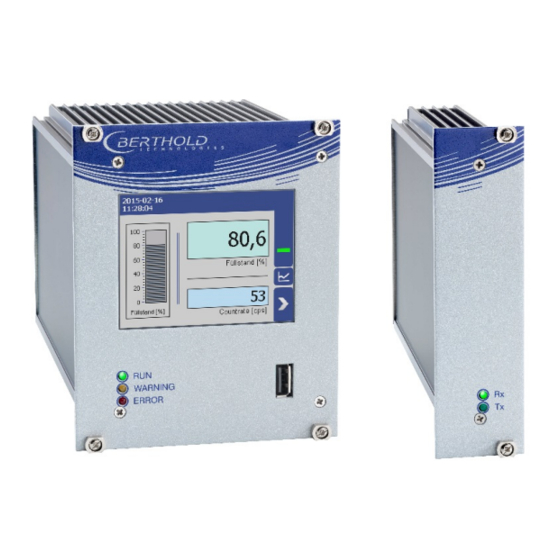
3 System Description LB 470RID Level 3.4.2 Front/rear View Master EVU Front View Master EVU The following control elements are found on the front of the master EVU: • LEDs for status display of individual operating states • 3.5“ Touch display •... - Page 27 LB 470RID Level 3 System Description Status displays of the master EVU The LEDs (Fig. 4, items 2-4) below the touch display show the current operating status of the master EVU. Display LED Description This LED lights up green if the device is in operation and fault-free.
- Page 28 3 System Description LB 470RID Level Rear view master EVU The following connections are located on the back of the EVU: • Master/slave connector, 4-pin • RJ45 socket for Ethernet • 32-pin plug connector Master/slave 4-pin connector RJ45 socket for Ethernet 32-pin plug connector Fig.
-
Page 29: Front/Rear View Slave Module
LB 470RID Level 3 System Description 3.4.3 Front/rear View Slave Module The LEDs Rx and Tx are found on the front of the slave module. • The LED Rx flashes green when data is received. • The LED Tx flashes green when data is sent. •... -
Page 30: Measurement Arrangements
3 System Description LB 470RID Level Measurement Arrangements The detector and/or the source are rod-shaped for a radiometric level measure- ment, so as to form a triangular or rectangular useful beam field. The change of the measurement signal for different level results from the different sized covering of the radiation field. - Page 31 LB 470RID Level 3 System Description Point source / shield Mounting base with source min / max level Radiation field Rod detector 1 + 2 Rod detector 1 + 2 (side view) Measurement line (1st detector - master EVU) Measurement line (2nd detector - slave module) Connection master EVU - slave module Master EVU Slave module...
- Page 32 3 System Description LB 470RID Level Mounting base Rod source / shield Mounting base with source Min/max level Radiation field Upper marking groove Rod detector Lower marking groove Fig. 10 Schema rod source - rod detector Mounting base Rod source / shield Mounting base with source Min/max level Radiation field...
-
Page 33: Storage
LB 470RID Level 3 System Description Min / max level Point source in the dip tube Shield Radiation beam Detector Fig. 12 Schema point source - point detector (absorption level measurement) The detector and the source are usually formed as points in an absorption level measurement. - Page 34 3 System Description LB 470RID Level 56925-1BA2 Rev.02, 05/2021...
-
Page 35: Installation
The applicable national regulations of the country of use have to be observed! Repair and maintenance on the devices may only be performed by experts (see chapter 2.3). In case of doubt, the complete device must be returned to Berthold for repair. -
Page 36: Mounting The Wall Housing
4 Installation LB 470RID Level Mounting the Wall Housing Observe the permitted ambient conditions (refer to document "Technical Infor- mation" in the appendix). NOTICE It is recommended that the wall housing be protected from direct sun- light in order to maintain maximum ambient temperature (refer to “Technical Information”). -
Page 37: Installation In The Wall Housing
LB 470RID Level 4 Installation Installation in the Wall Housing The wall housing may be equipped differently, depending on requirements (refer to document “Technical Information”). To do this, a corresponding terminal panel is located in the wall housing. NOTICE The master EVUs / slave modules must be secured against pulling out by fix- ... - Page 38 4 Installation LB 470RID Level Installation of the modules (master-master) Master-slave connector Socket board Guide rails Fixing screws Fig. 15 Installation of the modules (master-master) Set modules into the guide rails and push it gently until the plug connector of the module (Fig. 15, item 2) is inserted into the socket board. Tighten all fixing screws (Fig.
-
Page 39: Installation In The 19" Subrack
LB 470RID Level 4 Installation Installation in the 19" Subrack The 19" subrack can be equipped differently, depending on requirements (see doc- ument “Technical Information”). The rear clamp blocks (Fig. 16, item 3) or terminal panels (Fig. 17, item 4) are used for the electrical connection. NOTICE The 19"... -
Page 40: Installation With Clamp Blocks
4 Installation LB 470RID Level 4.6.1 Installation with Clamp Blocks j DANGER Danger to life from electric shock! Installation/maintenance may only be carried out if the device has been de- energized. Test of absence of harmful voltages when the front side is open. ... -
Page 41: Installed With Terminal Panels
LB 470RID Level 4 Installation 4.6.2 Installed with Terminal Panels j DANGER Danger to life from electric shock! Installation/maintenance may only be carried out if the device has been de- energized. Test of absence of harmful voltages when the front side is open. ... - Page 42 4 Installation LB 470RID Level 56925-1BA2 Rev.02, 05/2021...
-
Page 43: Electric Installation
LB 470RID Level 5 Electric Installation Electric Installation General Instructions j DANGER Danger to life from electric shock! The installation may only be carried out by a qualified electrician. Please adhere to the relevant safety regulations. Open the housing only in a dry environment and for installation, mainte- ... -
Page 44: Circuit Breaker
(there and back) of 40 ohms. For standard cables from Berthold (Mat. No. 32024), this results in a cable length of 1000m, from the evaluation unit to the detector. -
Page 45: Cable Glands And Blanking Elements
Cable bushings and blanking elements must comply with the applicable IP pro- tection class and with the requirements for the operational environment. We recommend ordering missing cable glands, blanking elements or adapters from Berthold. 56925-1BA2 Rev.02, 05/2021... -
Page 46: Protective Earth And Equipotential Bonding
5 Electric Installation LB 470RID Level 5.1.4 Protective Earth and Equipotential Bonding The protective earth conductor has to be connected to the terminals marked with "PE". The housing must be connected to local equipotential bonding. 5.1.5 EIA-485 (RS-485) Network For integration of EVU units into an EIA-485 (RS-485) network, all participants must be connected one after the other in the configuration Master-Master. -
Page 47: Exchange Lb 44X To Lb 47X
LB 470RID Level 5 Electric Installation Exchange LB 44x to LB 47x NOTICE If you install a DuoSeries LB 47x transmitter, in order to replace a LB 44x, it is necessary to consider an incompatibility in the connecting terminals. In the most unfavorable case a short circuit in the connected terminals ... -
Page 48: Electric Connection In The Wall Housing
5 Electric Installation LB 470RID Level Electric Connection in the Wall Housing j DANGER Danger to life from electric shock! The installation may only be carried out by a qualified electrician. Please adhere to the relevant safety regulations. Installation/maintenance may only be carried out if the device has been de- ... - Page 49 LB 470RID Level 5 Electric Installation Run the cables through the cable glands (Fig. 19, item 6) through the open- ings of the wall housing and through the counternut cable glands (Fig. 19, item 7). Screw the cable glands (Fig. 19, item 6) with the counternut cable glands (Fig.
-
Page 50: Electrical Connection In A 19" Subrack With Terminal Board
5 Electric Installation LB 470RID Level Electrical Connection in a 19" subrack with Terminal Board j DANGER Danger to life from electric shock! The installation may only be carried out by a qualified electrician. Please adhere to the relevant safety regulations. ... - Page 51 LB 470RID Level 5 Electric Installation Opening terminal connection Voltage output Stripped wire Marking supply voltage Connection detector RJ45 connector (network) Supply voltage PE connection Fig. 20 Electrical connection in the 19" subrack NOTICE Apply the voltage of the specified and marked (Fig. 20, item 6) range only! Note the specification relating to Cables, Protective earth, equipotential ...
- Page 52 5 Electric Installation LB 470RID Level NOTICE Note the specification relating to Protective earth and equipotential bonding in chapter 5.1.4. The connection was made correctly. 56925-1BA2 Rev.02, 05/2021...
-
Page 53: Electrical Connection In The 19" Subrack With Clamp Block
LB 470RID Level 5 Electric Installation Electrical connection in the 19″ subrack with clamp block j DANGER Danger to life from electric shock! The installation may only be carried out by a qualified electrician. Please adhere to the relevant safety regulations. ... - Page 54 5 Electric Installation LB 470RID Level Terminal screw (M2.5) RJ45 connector (network) Opening terminal connection PE connection 4-pin master/slave plug (only master EVU) ter- minals 41-44 Fig. 21 Electrical connection in the 19″ component rack (Ex.: 4x Master) Unused slots must be closed with blinds. Connect the lines to the clamp blocks according to assignment (see 2.5 As- signment Terminal Block Master EVU or 2.6 Assignment Terminal Block Slave in “Technical Information”).
-
Page 55: Master/Slave Plug
LB 470RID Level 5 Electric Installation 5.5.1 Master/Slave Plug The master/slave plug is used by applications with terminal blocks. Further infor- mation on the connection can be found in chapters 2.5 Assignment Terminal Block Master EVU and 2.7Assignment Terminals Master/Slave Plug under “Technical In- formation”. -
Page 56: Switching Current Output
5 Electric Installation LB 470RID Level Switching Current Output Switching between "SOURCE" (active) and "SINK" (passive) is possible using the slide switch on the I/O board. Factory setting EVU is delivered in "SOURCE" mode. Please note that the polarity at the current output must be inverted as soon as the current output is switched at the switch. -
Page 57: Operation Of The Software
LB 470RID Level 6 Operation of the Software Operation of the Software System Start Fig. 24 Start screens with display of the software version System start with invalid application software A different menu structure is present in this mode. Fig. 25 Start screen (Invalid application software) IMPORTANT The communication between the sensor and EVU is limited to 1200 baud. -
Page 58: Evu Standard Display
6 Operation of the Software LB 470RID Level EVU Standard Display IMPORTANT Changing the language of the user interface is changed in menu Device Setup | Setup | System | Interfaces | Languages. Description of the measuring point Button “Diagram” Date and Time State information Level scale... -
Page 59: Navigation
LB 470RID Level 6 Operation of the Software Navigation Home (standard display) Diagram display Data One menu level back One menu level forward Fig. 27 Icons for navigation 56925-1BA2 Rev.02, 05/2021... -
Page 60: Diagram Display
6 Operation of the Software LB 470RID Level 6.3.1 Diagram Display Clicking the diagram symbol (Fig. 26, item 5) changes the view to the diagram dis- play. The arrow keys (Fig. 28, item 1) are used to switch between the diagrams Level –... -
Page 61: Event Reports
LB 470RID Level 6 Operation of the Software 6.3.3 Event Reports Events are displayed in the standard display and in the submenus and windows as a symbol. All events are displayed on the main screen. A specific “D” (for detector) indicates that a detector has an event, the prefix “M”... -
Page 62: Input Field
6 Operation of the Software LB 470RID Level IMPORTANT If you click the button <Close>, the event message is closed, the icon continues to be displayed. Input Field NOTICE The input field appears by clicking on the blue display panels. Input line Input key Shift key for numbers... -
Page 63: Main Menu Device Setup
LB 470RID Level 7 Main Menu Device Setup Main Menu Device Setup Main Menu - Device Setup Identfification Chap. 7.1 Location Device Information Access Chap. 7.2 Setup Chap. 7.3 Calibration System Sensors Measurement Signal-Condition Detector Calibration Settings Date / Time Damping Configuration Calibrate... -
Page 64: Menu Identification
7 Main Menu Device Setup LB 470RID Level Fig. 32 Menu “Main Menu”, "Device Setup" Menu Identification Device Setup | Identification You can make the following settings and read information in the Identification menu: • Display and change the location name •... -
Page 65: Location
LB 470RID Level 7 Main Menu Device Setup 7.1.1 Location Device Setup | Identification | Location The location of the evaluation unit is displayed (Fig. 34, item 1) in the “Location” menu. The name can only be edited (7.2 Menu Access) in the access level "Stand- ard". -
Page 66: Device Information
7 Main Menu Device Setup LB 470RID Level 7.1.2 Device Information Device Setup | Identification | Device Information Information about hardware and software of the evaluation unit are displayed in the submenu "Device Information". CU update (Control Unit) Device Information MU update (Measurement Unit) Selection window update file Software versions... -
Page 67: Perform Software Update
The secured settings should then be imported after the successful software update. The current software versions can be downloaded from the Berthold website (www.berthold.com). Perform CU Update Save the current update file of the CU software on a USB storage device. - Page 68 EVU. The device restarts and the new MU software has been installed. NOTICE Berthold recommends calibrating the current outputs whenever a module has been installed/replaced or if a software update has been carried out. 56925-1BA2 Rev.02, 05/2021...
-
Page 69: Access
LB 470RID Level 7 Main Menu Device Setup Access Device Setup | Access You can set the user rights via the user levels and assign passwords in the window “Access”. After assigning a password the device is protected against unauthorized manipulation of the parameters. - Page 70 7 Main Menu Device Setup LB 470RID Level User Level Admin This access level is only intended for the system man- agement by Berthold. Automatic logout Activating the selection box (Fig. 39 item 1) auto- matically resets the access level Standard to “Basic”...
- Page 71 LB 470RID Level 7 Main Menu Device Setup Assign / change password To set or change a password, select "Standard" (Fig. 42, item 4) and click on <Change password> (Fig. 42, item 2) to open the input field. Input field Button <OK>...
-
Page 72: Menu Setup
7 Main Menu Device Setup LB 470RID Level Menu Setup Device Setup | Setup Fig. 38 Menu "Setup" 7.3.1 System (Date / Time, Interfaces, Units, Network, Reset, Repair Det. Software) Device Setup | Setup | System Fig. 39 Submenu "System" 56925-1BA2 Rev.02, 05/2021... - Page 73 LB 470RID Level 7 Main Menu Device Setup Set Date and Time Device Setup | Setup | System | Date / Time IMPORTANT The date and time must always be set correctly so that all records (log files) have the correct metadata. The correct date is also indispensable for the decay com- pensation.
- Page 74 7 Main Menu Device Setup LB 470RID Level Interfaces Device setup | Setup | System | interfaces You can adjust the following settings in the submenu “Interfaces” (Fig. 41): • Local Display o Brightness / Touch o Input / Output •...
- Page 75 LB 470RID Level 7 Main Menu Device Setup Brightness / Timeout Device Setup | Setup | System | interfaces | Local Display | Brightness / Timeout “Timeout” refers to the period of time during which the display is not operated. The value “Time out display brightness”...
- Page 76 7 Main Menu Device Setup LB 470RID Level Input / Touch Device Setup | Setup | System | Interfaces | Local Display | Input / Touch | Calibrate Touchscreen The mouse pointer automatically becomes visible when a mouse is inserted into the USB port.
- Page 77 LB 470RID Level 7 Main Menu Device Setup Confirm the calibration by clicking on the white screen to go back to "In- put/Touch" Execute a restart of the EVU after prompting. The touch display is calibrated. Language Device Setup | Setup | System | interfaces | Language Selection arrow Information window Fig.
- Page 78 7 Main Menu Device Setup LB 470RID Level CE Remote Control Device Setup | Setup | System | interfaces | Local Display | Remote Control By activating (Fig. 47, item 1) the CE Remote Control, the unit can be operated via the network connection.
- Page 79 LB 470RID Level 7 Main Menu Device Setup Units Device Setup | Setup | System | Units Clicking on the individual selection arrow lists the available units for the measuring value. The selected unit is shown in the standard display and used in the calibration settings.
- Page 80 7 Main Menu Device Setup LB 470RID Level Network Device Setup | Setup | System | Network In the Network settings window, you can make changes to the network settings. The information can only be edited in the access level "Standard" (see chap. 7.2 Menu Access).
- Page 81 LB 470RID Level 7 Main Menu Device Setup Remote Control Software If the EVU is connected to a network at the RJ45 socket (Fig. 5, item 2), the EVU can be operated via a computer. The software can be loaded onto a USB storage device (see chapter “CE Remote Control”).
- Page 82 7 Main Menu Device Setup LB 470RID Level Reset Device (Evaluation Unit) Device Setup | Setup | System | Reset Device The evaluation unit can be restarted and reset to factory settings in the window “Reset device”. Button Reboot Button Factory settings Window “Warning: Reboot”...
- Page 83 Corresponding information is displayed to the user in this menu. The current software versions for the detectors can be downloaded from the Berthold website (www.berthold.com). 56925-1BA2 Rev.02, 05/2021...
-
Page 84: Sensors
7 Main Menu Device Setup LB 470RID Level 7.3.2 Sensors Device Setup | Setup | Sensors You can perform the following settings and read information in the submenu “Sensors”: • Detector configuration (Fig. 53, item 1) o Add / Remove detectors o Settings of the detectors •... - Page 85 LB 470RID Level 7 Main Menu Device Setup Detector Configuration Device Setup | Setup | Sensors | Detector Configuration In the window “Detector Configuration” the detectors for the measuring system are added and configured. Only configured detectors are listed and shown in the menu (Fig.
- Page 86 7 Main Menu Device Setup LB 470RID Level Detector Settings The settings of a configured detector are edited by selecting and clicking on <Edit> (Fig. 54, item 3). IMPORTANT For systems with a single detector, window A is displayed. For cascaded systems, window B is displayed.
- Page 87 LB 470RID Level 7 Main Menu Device Setup Configure a cascaded system Note the arrangement of the system components during configuration (see chap- ter 3.2 Measuring Principle). Selection box “Cascaded measurement” Button <Search> Button < + > Window “Search for Detectors” Button <Edit>...
- Page 88 7 Main Menu Device Setup LB 470RID Level Detector Settings Device Setup | Setup | Sensors | [NAME DETECTOR] You can adjust the following settings and read information in the submenu of the respective detector: • Overview of count rate, HV value and temperature •...
- Page 89 LB 470RID Level 7 Main Menu Device Setup Detector Settings: Overview Device Setup | Setup | Sensors | [NAME DETECTOR] | Overview All important parameters and measured values of the detector are clearly displayed in the window “Overview”. Status information of the detector Device ID Live rate [cps] HV mode...
- Page 90 “Plateau” (Fig. 59) leads to the plateau measuring and the display of plateau val- ues. Please contact your responsible service or sales partner, or Berthold directly, so that they can get a qualified assessment to the measured plateau. Fig. 59 Menu "Plateau"...
- Page 91 Plateau Settings Device Setup | Setup | Sensors | [NAME DETECTOR] | Plateau | Plateau Settings The values in the window “Plateau settings” are pre-set by Berthold on delivery and can be used in most situations. Input field HV start value in volts...
- Page 92 7 Main Menu Device Setup LB 470RID Level Perform Plateau Measurement Device Setup | Setup | Sensors | [NAME DETECTOR] | Plateau | Plateau Measurement IMPORTANT The environmental conditions and the dose rate must be constant during the plateau recording. Observe the operating manual of the detector.
- Page 93 LB 470RID Level 7 Main Menu Device Setup The recorded values are read and entered into the table (Fig. 62), the plateau curve (Fig. 63) is drawn and stored automatically. Plateau Table Device Setup | Setup | Sensors | [NAME DETECTOR] | Plateau | Plateau Table The data from each measurement point are listed in the plateau table.
- Page 94 7 Main Menu Device Setup LB 470RID Level Plateau Curve Device Setup | Setup | Sensors | [NAME DETECTOR] | Plateau | Plateau Curve The mapped characteristic curve (Fig. 63, item 2) of the last complete plateau meas- urement is displayed in the window “Plateau Curve”. Date and Time of measurement recording Characteristic curve Fig.
- Page 95 LB 470RID Level 7 Main Menu Device Setup Detector Settings: Temperature Device Setup | Setup | Sensors | [NAME DETECTOR] | Temperature The current temperature and the extreme values of the detector is displayed in the window “Temperature". Current temperature of the detector [°C] Maximum measured temperature [°C] Minimum measured temperature [°C] Fig.
- Page 96 7 Main Menu Device Setup LB 470RID Level Detector Settings: High Voltage | Detector Type Device Setup | Setup | Sensors | [NAME DETECTOR] | High Voltage | Detector Type Internal device parameters are adjusted to suit the size of the used scintillator by setting the detector code.
- Page 97 LB 470RID Level 7 Main Menu Device Setup NOTICE Default HV is preset by Berthold. A subsequent change is not usually necessary. The default value HV = 0 may only be set for testing purposes. An incorrect setting may cause malfunction.
- Page 98 7 Main Menu Device Setup LB 470RID Level Detector Settings: Detector Service Device Setup | Setup | Sensors | [NAME DETECTOR] | Detector Service You can adjust the following settings and read information in the submenu “Ser- vice": • Device Information •...
- Page 99 An update of the firmware of the detector may take 1 hour and may only be per- formed by qualified specialists. Tipp The current software versions can be downloaded from the Berthold website (www.berthold.com). IMPORTANT In order for the system to detect the update file it must not be located in an in- dex in the USB storage device.
- Page 100 7 Main Menu Device Setup LB 470RID Level NOTICE Berthold recommends a test or a calibrating the current outputs whenever if a software update has been carried out. Detector Settings: Service | Event Log Device Setup | Setup | Sensors | [NAME DETECTOR] | Detector Service | Event Log The last 25 events of the detector are displayed in the window "Event Log".
- Page 101 LB 470RID Level 7 Main Menu Device Setup Detector Settings: Detector Service | Event Overview Device Setup | Setup | Sensors | [NAME DETECTOR] | Detector Service | Event Over- view All events that can be logged are chronologically presented in tabular form in the window “Event overview”.
- Page 102 7 Main Menu Device Setup LB 470RID Level Detector settings: Detector Service | Reset Detector Device Setup | Setup | Sensors | [NAME DETECTOR] | Detector Service | Reset Detec- In the window “Reset Detector”, the detector can be restarted and be reset to the factory settings.
-
Page 103: Calibration
This may possibly lead to loss of production or to damage in the system. We encourage you to have the calibration and commissioning performed by Berthold service. IMPORTANT The RID function must be activated in the menu Device Setup | Setup | Signal ... - Page 104 7 Main Menu Device Setup LB 470RID Level Basic Setup Device Setup | Setup | Calibration | Basic Setup Checkbox “Inverted Curve” Calibration “1 Point Exp.” Selection calibration Type Calibration “2 Point Exp.” Calibration “Linear” Fig. 74 Basic Setup Calibration Method The method by which the measuring system must be calibrated depends on the respective measuring arrangement.
- Page 105 LB 470RID Level 7 Main Menu Device Setup Calibration Settings: Background Device Setup | Setup | Calibration | Calibration Settings The background count rate (Fig. 76, item 1) is the natural background radiation seen by the detector and must be measured at least for rod detectors. This count rate is compensated for by the system.
- Page 106 7 Main Menu Device Setup LB 470RID Level Input field Background [cps]; Meas. Channel Count rate RID Input field Background (RID); Second channel Input field “read in time” Button <Ok> Button <Start> Input field count rate Button <Cancel> Fig. 76 Calibration Parameters: Background Determine Background Device Setup | Setup | Calibration | Calibration Settings...
- Page 107 LB 470RID Level 7 Main Menu Device Setup Calibration Settings: Nuclide Device Setup | Setup | Calibration | Calibration Settings The isotope used can be selected in the “Nuclide” tab. The half-life of the isotope is shown on the display field (Fig. 77, item 1). NOTICE The sources for level measurement and the sources of the GPC measurement must contain the same Nuclide.
- Page 108 7 Main Menu Device Setup LB 470RID Level Calibration Settings: PV Range Device Setup | Setup | Calibration | Calibration Settings Input field “PV lower range value” [%] Input field “PV upper range value” [%] Fig. 79 Calibration Parameters (PV Range) PV Range Value Lower limit of the measuring range.
- Page 109 LB 470RID Level 7 Main Menu Device Setup Calibration Settings: Table (linear calibration type) Device Setup | Setup | Calibration | Calibration Settings Column count rate [%] Count of the calibration points Column count rate [cps] Read-In-Time [s] Column count rate [rid] Count rate RID [cps] Button <Edit>...
- Page 110 7 Main Menu Device Setup LB 470RID Level Calibration Settings: Table (2 Point Exp. calibration type) Device Setup | Setup | Calibration | Calibration Settings Column count rate [%] Count of the calibration points Column count rate [cps] Read-In-Time [s] Column count rate [rid] Count rate RID [cps] Button...
- Page 111 LB 470RID Level 7 Main Menu Device Setup Calibration Settings: Table (1 Point Exp. calibration type) Device Setup | Setup | Calibration | Calibration Settings The absorption coefficient, the measuring path and the product density must be known. The second calibration point is thereby calculated. Column count rate [%] Read-In-Time [s] Column count rate [cps]...
- Page 112 7 Main Menu Device Setup LB 470RID Level Enter the absorption coefficient of the product. Enter it with a negative pre- fix. Unless it is one of the very rare applications with an inverted characteristic. 10. Enter the product density. 11.
- Page 113 LB 470RID Level 7 Main Menu Device Setup Calibrate Device Setup | Setup | Calibration Data that are necessary for a complete measurement are found in the calibration parameter set. All the data of the calibration parameter set are transferred to the measurement parameter set when the button “Calibrate”...
- Page 114 7 Main Menu Device Setup LB 470RID Level Recall Device Setup | Setup | Calibration | Recall Button <Recall> Window “Recall measurement to parameter set” Fig. 85 Recall Recall to calibration set Click on the button <Recall> if you want to copy the measurement set into the calibration set.
- Page 115 LB 470RID Level 7 Main Menu Device Setup Adjust: Standard Adjust Device Setup | Setup | Calibration | Adjust Use the functionality after source exchange or after entering a theoretical, normal- ized multi-point calibration (e.g. a Radical calculation) to adjust the table in the measuring set.
- Page 116 7 Main Menu Device Setup LB 470RID Level the duration of measurement in seconds. The higher you set the measure- ment time, the more accurate the result. Click <Ok> to accept the value. Click on the button <Perform adjust now> (Fig.
- Page 117 LB 470RID Level 7 Main Menu Device Setup Adjust: Low Level Adjust Device Setup | Setup | Calibration | Adjust After calibration, a level adjustment can be performed. A level adjustment must be performed if the level shown is not the actual level. The lower adjustment can only be performed at a level <...
- Page 118 7 Main Menu Device Setup LB 470RID Level A new window opens. Click on the button <Start> (Fig. 89, item The measurement starts. Click < Ok > to accept the values. The level has been adjusted to the process value (see standard display). ...
- Page 119 LB 470RID Level 7 Main Menu Device Setup Adjust: High Level Adjust Device Setup | Setup | Calibration | Adjust The upper adjustment can only be performed at a level > 50%. The count rate at 0% will be kept fixed, while all other points of the curve will be adjusted according to the adjusted count rate at the entered level value.
- Page 120 7 Main Menu Device Setup LB 470RID Level The measurement starts. Click <Ok> to accept the values. The level has been adjusted to the process value (see standard display). IMPORTANT When executing an adjust, the measurement parameter set was overwritten. If the system should be recalibrated, a recall of the measurement parameter set to the calibration parameter must be performed.
- Page 121 Slave module Fig. 92 GPC example measurement arrangement NOTICE This functionality presupposes comprehensive knowledge and should only be acti- vated by a Berthold service technician or a specially trained and instructed person. GPC = Gas Property Compensation 56925-1BA2 Rev.02, 05/2021...
- Page 122 • GPC settings • Reset GPC NOTICE An additional compatible Berthold probe for measuring the gas density is abso- lutely necessary for the gas properties compensation. The probe is connected to the level measurement via the slave interface. Fig. 93 Submenu „GPC“...
- Page 123 LB 470RID Level 7 Main Menu Device Setup GPC Calibration Device Setup | Setup | Calibration | GPC | GPC Calibration The "GPC calibration" is used to adapt the measuring sensitivity of the gas density detector to that of the level detector. The check box “GPC enabled”...
- Page 124 7 Main Menu Device Setup LB 470RID Level GPC Calibration: Reference Rate The reference count rate of the connected density measurement must be recorded at the same pressure at which the level calibration table was recorded. Therefore, it is recommended to read in the reference count rate immediately after recording the empty level count rate.
- Page 125 LB 470RID Level 7 Main Menu Device Setup GPC Calibration: Background The background count rate (Fig. 94, item 3) indicates the natural background radi- ation of the gas density detector if no radiation source is installed. This count rate is compensated by the system. Input field count rate [cps] Input field read-in time [s] Button...
- Page 126 7 Main Menu Device Setup LB 470RID Level GPC calibration: Factor M To calculate the correct factor M, click on the input field for the factor M. In this table the first calibration point can be inserted directly from the available data with the button <Add Reference>...
- Page 127 LB 470RID Level 7 Main Menu Device Setup Calculate Factor M After all values have been entered or calculated in the GPC calibration window, the GPC function can be activated with the "GPC activated" check box (Fig. 94, item 1). The “Factor M”...
- Page 128 7 Main Menu Device Setup LB 470RID Level GPC Nuclide Settings Device Setup | Setup | Calibration | GPC | GPC Nuclide Settings Under "GPC Settings" the isotope of the source for gas density measurement can be selected (Fig. 98, item 1). The half-life time of the isotope is shown in the display field (Fig.
-
Page 129: Measurement
LB 470RID Level 7 Main Menu Device Setup 7.3.4 Measurement Device Setup | Setup | Measurement The window “Measurement” is used for an overview of the measurement param- eters and calibration settings used. Measurement: Parameter The parameters used for the current measurement are displayed in the “Parame- ters”... - Page 130 7 Main Menu Device Setup LB 470RID Level Measurement: Table The measurement points used for the current measurement are displayed in the “Table” tab. PV measurement point in percent [%] RID count rate [cps] Count rate [cps] Date of last change of the measurement parameter set Number of measuring points Fig.
-
Page 131: Signal Condition
LB 470RID Level 7 Main Menu Device Setup 7.3.5 Signal Condition Device Setup | Setup | Signal Condition You can perform the following settings and read information in the “Signal Con- dition” submenu: • Damping (time constant) • PV range •... - Page 132 7 Main Menu Device Setup LB 470RID Level Confirm the value with the Enter key. The time constant has been changed. Signal Condition: PV Range Device Setup | Setup | Signal Condition | PV Range The lower and upper limit of the process range of the active measuring parameter set can be set in the tab “PV Range”...
- Page 133 LB 470RID Level 7 Main Menu Device Setup Signal Condition: Rapid Switch Device Setup | Setup | Signal Condition | Rapid Switch IMPORTANT The use of the function "Rapid Switch" is recommended only for special appli- cations where the output signal has to adapt rapidly to the new value, e.g. in case of measurements on small tanks and if sudden level changes occur.
- Page 134 7 Main Menu Device Setup LB 470RID Level Signal processing: XIP (Radiation Interference) Device Setup | Setup | Signal Condition | XIP This function allows you to take interference (XIP) into consideration. Measure- ment jumps that influence the process can arise through interference. Only rapid increases are considered.
- Page 135 LB 470RID Level 7 Main Menu Device Setup Detecting Interference Radiation XIP Pipe Welding seam tests with X-rays Radiation interference Distance up to 200 m Level Measurement Fig. 108 Interference radiation during a weld inspection Detecting Interference Radiation The high Gamma sensitivity of scintillation detectors may cause a false reading. To detect interfering radiation, a double plausibility check can be enabled.
- Page 136 7 Main Menu Device Setup LB 470RID Level Further information on scenario A A relative limit value is monitored, i.e. the alarm threshold is reached when exceed- ing a maximum dose rate (calibration value at empty vessel) at the detector. False alarms due to operative factors are not possible.
- Page 137 LB 470RID Level 7 Main Menu Device Setup Interference Radiation Detection Flow Chart If radiation interference is detected, following will happen: − Measured value and current output are Interference "held". radiation detected − Error relay indicates alarm. The measurement is "held" up to the end of the defined waiting time.
- Page 138 <Reset RID Table> Fig. 109 Signal Condition (RID) NOTICE The following parameters should be changed only by Berthold employees, or in consultation with Berthold. Explanation "Weight" The RID table consists of 100 points. Through these points, a characteristic curve is formed from the function between the secondary channel and the measurement channel.
- Page 139 LB 470RID Level 7 Main Menu Device Setup PV Threshold External radiation is detected if the measured value in the secondary channel deviates from the measurement channel by the value of PV Thresh- old. The larger the value, the more unclear the external radiation is detected.
- Page 140 7 Main Menu Device Setup LB 470RID Level Recommended Parameters Default Settings (slow) recommended settings Recommended settings for level applications in for limit switches and for which the measuring level measurements range is passed through where an almost constant level is used during opera- frequently and widely.
- Page 141 LB 470RID Level 7 Main Menu Device Setup Signal Processing: Source Replacement Device Setup | Setup | Signal Condition | Source Replacement Notification for a source replacement can be activated in this window. The mainte- nance message “Replace source” when this date is reached. NOTICE For radiation protection reasons, a source replacement is recommended after 15 years.
-
Page 142: Inputs
7 Main Menu Device Setup LB 470RID Level 7.3.6 Inputs Device Setup | Setup | Inputs The two digital inputs (DI) can be set, as well as displaying the DI status, in the submenu Inputs. Fig. 111 Menu "Inputs“; Submenu "Digital inputs (DI)“ 56925-1BA2 Rev.02, 05/2021... - Page 143 LB 470RID Level 7 Main Menu Device Setup Digital inputs (DI) Assignment Device Setup | Setup | Inputs | Digital Inputs | Assignment The menu Assignment determines which function is executed when the digital in- put is switched. In the "ACTIVE" state, the selected function is executed. The active state is initiated by closing the digital input.
- Page 144 7 Main Menu Device Setup LB 470RID Level DI State Device Setup | Setup | Inputs | Digital Inputs | DI State The states of the two digital inputs are displayed in the window “DI State”. DI Input 1 state (ACTIVE / PASSIVE) DI Input 2 state (ACTIVE / PASSIVE) Fig.
-
Page 145: Outputs
LB 470RID Level 7 Main Menu Device Setup 7.3.7 Outputs Device Setup | Setup | Outputs You can make the following settings and read information in the submenu “Out- puts”: • Analog Output Mapping (AO) o Function o AO monitoring o Failure mode o Current limits o Calibrate... - Page 146 7 Main Menu Device Setup LB 470RID Level Analog Output: AO Mapping Device Setup | Setup | Outputs | Analog Output (AO) | AO Mapping A function can be assigned to an analogue output in the window “AO Mapping”. The current output signal is between 4 mA and 20 mA. The corresponding values (e.g.
- Page 147 LB 470RID Level 7 Main Menu Device Setup Analog Output: AO Monitoring Device Setup | Setup | Output | Analog Output (AO) | AO Monitoring If “AO Monitoring” is activated (Fig. 116, item 1), the current output will be mon- itored.
- Page 148 7 Main Menu Device Setup LB 470RID Level Analog Output: AO Failure Mode Device Setup | Setup | Output | Analog Output (AO) | AO Failure Mode The alarm function is set when an error is detected at the current output in the window “AO Failure Mode”.
- Page 149 LB 470RID Level 7 Main Menu Device Setup Analogue Output: AO Limits Device Setup | Setup | Output | Analog Output (AO) | AO Limits By clicking on the input fields (Fig. 118, item 1, item 2), the values [mA] for the lower and upper current limit can be set.
- Page 150 For calibration of the current output, an ammeter (not included in the scope of delivery) is required, which is connected to the current output. Berthold recommends calibrating the current outputs whenever a module has been installed/replaced or if a software update has been carried out.
- Page 151 LB 470RID Level 7 Main Menu Device Setup Perform calibration j DANGER Danger to life from electric shock! The calibration may only be carried out by a qualified electrician. Observe the relevant safety regulations. Only open the device when free of voltage. ...
- Page 152 7 Main Menu Device Setup LB 470RID Level Digital Outputs (DO) Device Setup | Setup | Output | Digital Outputs (DO) The signals of the digital outputs are switched via potential-free relay contacts. The contacts are controlled “fail safe”, i.e., in the event of an alarm, the current at the relay coil drops and the NO contact (normally open) is opened.
- Page 153 LB 470RID Level 7 Main Menu Device Setup For example, Simulation, plate space meas- urement, and detector update. System State: Warning The relay alarms when the event message “Warning” is displayed. (Warning includes “Out of specification”, “function check” and “maintenance required”). Interference Radiation Alarm According to intensity of the interference radiation at the detector, one of three operating states of the measuring equipment is recognized...
-
Page 154: Alarms
7 Main Menu Device Setup LB 470RID Level 7.3.8 Alarms Device Setup | Setup | Alarms You can make the following settings and read information in the submenu "Alarms": Fig. 121 Menu "Alarms" PV Alarm Behavior Device Setup | Setup | Alarms | PV Alarm Behavior The behavior in case of alarm (NE107 Status) for the process value can be set in the window “PV Alarm Behavior”. - Page 155 LB 470RID Level 7 Main Menu Device Setup PV Alarm Settings Device Setup | Setup | Alarms | PV Alarm Settings You can set the values for the level alarms (max. and min.) and the hysteresis of these in the window “PV Alarm Settings”. When exceeding or falling below the switching point, an event message appears in the status display.
- Page 156 7 Main Menu Device Setup LB 470RID Level Det.-Temp. Alarm Behavior Device Setup | Setup | Alarms | Det.-Temp. Alarm Behavior The behavior in case of alarm (NE107 status) can be set for the detector tempera- ture in the window “Det.-Temp. Alarm Behavior“. Selection arrow NE107 Status Selection “No Status”...
- Page 157 LB 470RID Level 7 Main Menu Device Setup Detector Temperature Alarm Settings Device Setup | Setup | Alarms | Det.-Temp. Alarm Settings The values for the detector temperature (max. and min.) can be set in the window “PV Det.-Temp. Alarm Settings”. When there is exceeding or falling below the switching point, an event message appears in the status display.
-
Page 158: Simulation
7 Main Menu Device Setup LB 470RID Level 7.3.9 Simulation Device Setup | Setup | Simulation A check for the following functions can be performed in the submenu “Simula- tion”. Fig. 126 Menu "Simulation" NOTICE When starting a simulation, the measurement is stopped and a status message appears. - Page 159 LB 470RID Level 7 Main Menu Device Setup Simulation Analog Output Device Setup | Setup | Simulation | Analog Output Input field “Nominal” Display field “Actual” [mA] Button <Disable Test Mode> Fig. 127 Simulation Analog Output Click on the input field (Fig. 127, item 1) and enter the target value for the simulation.
- Page 160 7 Main Menu Device Setup LB 470RID Level Simulation Digital Output Device Setup | Setup | Simulation | Digital Output ERROR (DO-1) ALARM (DO-2) ALARM (DO-3) Button <Disable Test Mode> Dropdown field Fig. 128 Simulation Digital Outputs Click on the dropdown field (Fig. 128, item 5) and select "FAILURE" or “ALARM”...
- Page 161 LB 470RID Level 7 Main Menu Device Setup Simulation Count Rate Device Setup | Setup | Simulation | Count Rate Input field Dampened count rate Display field process value “PV” Button <Disable Test Mode> Fig. 129 Simulation Count Rate Click on the input field (Fig. 129, item 1) and enter count rate for the simula- tion.
- Page 162 7 Main Menu Device Setup LB 470RID Level Simulation Level Device Setup | Setup | Simulation | Level Input field level Button <End test mode> Fig. 130 Simulation Level Click on the input field (Fig. 130, item 1) and enter a value for the simulation. Confirm with the Enter key.
-
Page 163: Menu Backup/Restore
LB 470RID Level 7 Main Menu Device Setup Menu Backup/Restore Device Setup | Backup/Restore You can make a backup copy of the configuration data, and perform a recovery in the submenu Backup/Restore. Fig. 131 Menu "Backup/Restore" 7.4.1 Backup Device Setup | Backup/Restore | Backup Button <Backup>... - Page 164 7 Main Menu Device Setup LB 470RID Level The window ”Enter description” appears. The message ”Error free” (Fig. 132, item 3) appears in the field “Backup data” for error-free backup files. Click the button <Edit>, enter a description, and confirm with the Enter key. Click on the button <Save>.
-
Page 165: Restore
LB 470RID Level 7 Main Menu Device Setup 7.4.2 Restore Device Setup | Backup/Restore | Restore Button < “previous” Number of recovery files on the USB storage device Button > ”next” Button <Restore> Recording date of the backup file Time of backup file recording Information about the backup data (error / error free) Confirmation window Fig. -
Page 166: Main Menu Diagnostics
8 Main Menu Diagnostics LB 470RID Level Main Menu Diagnostics Main Menu | Diagnostics Change Log Data Log Network Data Log Export Service Data Transmitter Transmitter Temperature Events Transmitter Event Log Transm. Event Overview Fig. 134 Menu "Diagnostics" Transmitter Temperature Diagnostics | Transmitter Temperature Temperature values from the evaluation unit (processor) are displayed in the menu item “Transmitter Temperature”. -
Page 167: Events
LB 470RID Level 8 Main Menu Diagnostics Events Diagnostics | Transm. Events Fig. 136 Menu "Transm. Events" Information Events of the respective detector can be seen at Device Setup | Setup | Sensors | [NAME OF DETECTOR] | Detector Service. 8.2.1 Transmitter Event Log Diagnostics | Transmitter Events | Transmitter Event Log... - Page 168 8 Main Menu Diagnostics LB 470RID Level Display Event Description Button <?> Button <Clear event log> Highlighted event Event no. Event title Event description Button <Close> Fig. 138 Display an Event Log Information Click on a line in the list (Fig. 138, item 3). Click on <?>...
-
Page 169: Transm. Event Overview
LB 470RID Level 8 Main Menu Diagnostics 8.2.2 Transm. Event Overview Diagnostics | Transm. Events | Transm. Event Overview All events that can be logged are chronologically presented in tabular form in the window “Event overview”. Activate the check box “Non-zero Counter only 0” (Fig. 139, item 5) in order to display events that have occurred. -
Page 170: Change Log
8 Main Menu Diagnostics LB 470RID Level Change Log Diagnostics | Change Log You can track changes that were performed on the device in the window “Change Log”. Time of the change Short info of the change Old state New state Fig. -
Page 171: Data Log
LB 470RID Level 8 Main Menu Diagnostics Data Log Diagnostics | Data Log You can set the log interval as well as delete and export the log data in the sub- menu “Data log”. IMPORTANT The data cannot be viewed on the EVU Display or via Ethernet. The data must be exported to a USB storage device to view it on a PC. - Page 172 8 Main Menu Diagnostics LB 470RID Level Export log data Click on the button <Stop> (Fig. 141, item 2) to stop the data log process. Connect a USB storage device to the device (Fig. 3, item 5). Click on the button <Export>...
-
Page 173: Network Data Log
LB 470RID Level 8 Main Menu Diagnostics Network Data Log Diagnostics | Network Data Log In the window “Network data log”, the transmission of log data via the ethernet network can be started. With a log program, the data can be displayed on the PC. IMPORTANT The PC and the LB 47x have to be in the same IP subnet. -
Page 174: Export Service Data
8 Main Menu Diagnostics LB 470RID Level Export Service Data Diagnostics | Export Service Data Button <Export service data> Process window Confirmation message Fig. 144 Export Service Data Connect a USB storage device to the device (Fig. 3, item 5). The USB storage device is recognized by the system after a few seconds and the button <Export service data>... -
Page 175: Troubleshooting
LB 470RID Level 9 Troubleshooting Troubleshooting Error Search Problem Cause Measure Check power supply and Master unit: Screen black; LEDs fuses EVU does not work are not illuminated Check cabling, contact Slave module: Slave module not clamped sockets LEDs are not illuminated properly Check the functioning of... - Page 176 9 Troubleshooting LB 470RID Level Error Search (continued) Detector is not detected (soft- Check ID of the detector Incorrect ID in the configura- ware) (see type plate on the de- tion tector) Touch panel does not respond Error in operating system Restart EVU ...
-
Page 177: Error Codes Of The Evaluation Unit
LB 470RID Level 9 Troubleshooting Error Codes of the Evaluation Unit In the following tables you can find the EVU and detector error codes which give you exact information on how to fix them. The error codes of the detectors can be found in the operating instructions of the respective detectors. -
Page 178: System
Check, if mas- sive electromagnetic interferences have caused this event. Watchdog malfunction. Contact M105 WD Failure Berthold service, if this event occurs re- peatedly. Watchdog is inactive. Activate Watch- M106 WD Off Malfunction of the real-time clock. - Page 179 LB 470RID Level 9 Troubleshooting Failure of the external real time clock. M115 Extern RTC malfunction Contact Berthold service, if this event occurs repeatedly. The date could not be verified at M116 Corrupt Date startup. Check date and time and set if necessary.
-
Page 180: Application
Device not calibrated. Measurement M301 Default parameter set with default parameters. Calibrate de- vice Decay compensation failed. Contact Berthold service, if this event occurs re- M302 Decay compensation peatedly. Detector temperature at / below lower M303 Det Temp LL failure limit. - Page 181 LB 470RID Level 9 Troubleshooting Internal software failure. Restart the de- M399 Internal program err vice. Contact Berthold service, if this event occurs repeatedly. 56925-1BA2 Rev.02, 05/2021...
-
Page 182: Rid
9 Troubleshooting LB 470RID Level 9.2.3 56925-1BA2 Rev.02, 05/2021... - Page 183 LB 470RID Level 9 Troubleshooting If interference radiation is detected, then there are cases in which only a message (a code) is displayed. There are other cases where multiple messages (multiple codes) occur in combination. The previous list describes both cases. Because the errors overlap, only one error becomes visible.
-
Page 184: Detector
Lost connection to at least one detector. Check detector settings and connections. It is recommend to have the device M501 Detector not found checked by Berthold Service, even if it seems to work normally. Temporarily lost connection to at least one detector. Check detector settings M502 Detector comm. -
Page 185: Process Connection
NAMUR107 Help Text Deviation of analog output value from feeback value is too high. Calibrate ana- M701 Current output log output. Contact Berthold service, if this event occurs repeatedly. Current output loop open. Check cable M702 Current loop open connection. -
Page 186: Maintenance And Repair
Repair and servicing on the EVU may only be carried out by experts (see chapter 2.3). In case of doubt, the complete EVU is to be sent to Berthold. NOTICE Repair on electronic circuits on the circuit boards of a field device may only be carried out in the manufacturer's factory. -
Page 187: Replacing Of Fuses
LB 470RID Level 10 Maintenance and Repair 10.1 Replacing of Fuses j DANGER Danger to life from electric shock! Replacing of fuses may only be carried out by a qualified electrician. Please adhere to the relevant safety regulations. Installation/maintenance may only be carried out if the device has been ... - Page 188 10 Maintenance and Repair LB 470RID Level Replacing Fuse in the Master Module Fixing screws Fuse 250V 1A T (5x20 mm) Screws Base Housing Fuse 250V TR5 T80mA (Ø 8,5 mm) Covering fuse Fig. 145 Replacing fuses master EVU De-energize the device. Loosen the four fixing screws (Fig.
- Page 189 LB 470RID Level 10 Maintenance and Repair Replacing Fuse in the Slave Module Fixing screws Screws Housing Base Fuse Covering fuse Fig. 146 Exchange fuses slave EVU De-energize the device. Loosen the four fixing screws (Fig. 146, item 1) and remove the slave module from the wall housing or subrack.
-
Page 190: Cleaning
10 Maintenance and Repair LB 470RID Level 10.2 Cleaning The display is designed for maintenance-free operation. Make sure you keep the touch screen and keyboard membrane clean. Use a cleaning cloth dampened with a cleaning agent to clean the equipment. Only use water with a little liquid soap or a screen cleaning foam. -
Page 191: Data Backup
LB 470RID Level 10 Maintenance and Repair 10.3 Data Backup Activate the data log (see chapter 8.4) or the network data log (see chapter 8.5) so that all data are recorded. Perform a log data and service data backup at regular intervals. -
Page 192: Decommissioning
11 Decommissioning LB 470RID Level Decommissioning j DANGER Danger to life from electric shock! Decommissioning may only be carried out by qualified electricians. Please adhere to the relevant safety regulations. Decommissioning may only be carried out if the device has been de-ener- ... -
Page 193: Decommissioning 19" Subrack
LB 470RID Level 11 Decommissioning Loosen the lock (Fig. 149, item 2) using the supplied square key and pull the subrack out. The subrack can be folded down by the folding mechanism. Fold the subrack downward cautiously. Remove the network plug (Fig. 149, item 3). Remove all lines from the terminal board (Fig. -
Page 194: Disposal Of Measurement System
11 Decommissioning LB 470RID Level 11.3 Disposal of Measurement System j CAUTION Toxic! The product contains electronic components containing toxic substances that are harmful to health. Disposal is to be carried out in accordance with the disposal regulations via a disposal expert. - Page 195 LB 470RID Level 12 Appendix Appendix 12.1 Setup Protocol General data Date Measuring point Source No. Number of detectors LB 4700 LB 44xx LB 54xx Activity Isotope Cs-137 Co-60 Container Product Cascaded measurement Device configuration Model Installation variant Wall housing Subrack Anschluss Platine...
- Page 196 12 Appendix LB 470RID Level Setup Protocol (Continued) Parameters Password Language CE Remote Control enabled Network DHCP active IP Address Subnet Gateway DNS-Server MAC Address Calibration Linear Exponential inverted Curve Characteristic enabled Cs-137 Co-60 Damping time constant Process Value Range min.
- Page 197 LB 470RID Level 12 Appendix Parameters Digital Out- Function DO-2 Function DO-3 puts none none Low level alarm Low level alarm High level alarm High level alarm Det. temperature alarm Det. temperature alarm XIP alarm XIP alarm RID alarm RID alarm Source Replacement Alarm Source replacement alarm Measurement stopped...
- Page 198 Modifications due to technical advancement reserved. © BERTHOLD TECHNOLOGIES GmbH & Co. KG Language: English Printed in Germany 05/2021 Rev. No.: 02 BERTHOLD TECHNOLOGIES GmbH & Co. KG Calmbacher Str. 22 75323 Bad Wildbad Germany www.Berthold.com Mat No. 56925-1BA2...
- Page 199 Unité d'évaluation Détecteurs LB 47x LB 4700 Informations sur la sécurité 56925BA59 Rev. No.: 04, 09/2019...
- Page 200 1 A propos de ce manuel d’utilisation Informations sur la sécurité A propos de ce manuel d’utilisation Avertissement Les avertissements sont identifiés comme suit : Signalement Source et conséquence Explication si requise Prévention En cas de danger • Symboles d’alerte : (triangle d’alerte) attire l’attention sur le risque.
- Page 201 Informations sur la sécurité 1 A propos de ce manuel d’utilisation RECOMMANDATION Si cette information n’est pas appliquée, un dysfonctionnement et/ou un dégât matériel peuvent apparaître. IMPORTANT Les sections identifiées avec ce symbole signalent des informations importantes du produit ou de son fonctionnement. Fournit des conseils sur l’application ou d’autres informations utiles.
- Page 202 Informations sur la sécurité Conformité La société Berthold déclare par la présente, sous son entière responsabilité, que la conception de ce produit mis sur le marché par Berthold est conforme aux directives EU indiquées dans la déclaration de conformité originale.
- Page 203 • Effectuer les opérations de maintenance prescrites ou les faire réaliser pour vous ! • Utiliser uniquement les accessoires et pièces de rechange Berthold. Utilisation inappropriée à éviter: • Ne pas suivre les instructions de sécurité et les instructions pour l’utilisation, la maintenance et la mise au déchet indiquées dans le...
- Page 204 2 Sécurité Informations sur la sécurité Berthold assume la responsabilité de la garantie seulement dans le cadre de ses spécifications publiées. Si le produit est utilisé dans des conditions autres que celles décrites dans le présent manuel, la sécurité du produit est compromise et la garantie devient nulle.
- Page 205 Informations sur la sécurité 2 Sécurité Les obligations de l'opérateur L’opérateur de ces appareils doit régulièrement former son personnel sur les sujets suivants : • Connaissance et utilisation du manuel d’utilisation et des clauses légales. • Utilisation prévue de l’appareil. •...
- Page 206 Sous réserve de modifications dans le cadre du progrès technique. © BERTHOLD TECHNOLOGIES GmbH & Co. KG langue: Français Imprimé en Allemagne 09/2019 Rev.-Nr.: 04 BERTHOLD TECHNOLOGIES GmbH & Co. KG Calmbacher Str. 22 75323 Bad Wildbad Germany www.Berthold.com Id.-Nr. 56925BA59...
- Page 207 Level Füllstand Technical Information Technische Information 56925TI1L Rev. No.: 04, 05/2021...
- Page 208 Technical Information LB 470RID Level Technische Information LB 470RID Füllstand 1. Information on 2-Wire Technology The DuoSeries/DuoXPERT measuring system consists of a scintillation detector and a sophis- ticated evaluation unit (DuoXPERT) for display and operation. The evaluation unit is a state-of-the-art control unit with robust 3.5” TFT touch panel, pow- erful Dual Core CPU and diverse operator interfaces.
- Page 209 LB 470RID Level Technical Information LB 470RID Füllstand Technische Information 1.1. Measurement Arrangements with Rod Detector Messanordnungen mit Stabdetektor 1.1. TI-Abb. 1 Beispielhafte Messanordnungen mit Stabdetektor Exemplary measurement arrangements with rod detector 1.2. Measurement Arrangements with Point Detector Messanordnungen mit Punktdetektor 1.2.
- Page 210 Technical Information LB 470RID Level Technische Information LB 470RID Füllstand 2. Evaluation Unit The modules can be installed either in wall housings or 19" subracks. It can be equipped differently, depending on requirements. The rear clamp blocks or terminal panels are used for the electrical connection.
- Page 211 LB 470RID Level Technical Information LB 470RID Füllstand Technische Information 2.1. Installation Variants Wall Housing Installationsvarianten Wandgehäuse 2.1. TI-Abb. 3 Installation variants wall housing Installationsvarianten Wandgehäuse Item Compontens Connection Pos. Komponenten Anschluss 2 Master 1 Terminal panel master/master 1 Anschlussplatine Master/Master 1 Master, 3 Slaves 1 Terminal panel master/slave 1 Anschlussplatine Master/Slave...
- Page 212 Technical Information LB 470RID Level Technische Information LB 470RID Füllstand 2.2. Installation Variants 19” Subrack Einbauvarianten 19” Baugruppenträger 2.2. TI-Abb. 4 Installation variants 19” subrack Installationsvarianten 19” Baugruppenträger Item Compontens Connection Pos. Komponenten Anschluss 4 Master 2 Terminal panel master 2 Anschlussplatine Master 4 Master 4 Terminal blocks...
- Page 213 LB 470RID Level Technical Information LB 470RID Füllstand Technische Information 1 Master, 9 Slaves 10 Terminal blocks; master/slave plug 10 Klemmenblöcke; Master/Slave Stecker 11 Slaves 11 Terminal blocks 11 Klemmenblöcke Application example. The modules can be arranged arbitrarily with terminal blocks. Anwendungsbeispiele.
- Page 214 Technical Information LB 470RID Level Technische Information LB 470RID Füllstand 2.3. Connection Diagram Terminal Board Master/Master Anschlussplan Anschlussplatine Master/Master 2.3. TI-Abb. 5 Connection Diagram Terminal Board Master/Master Anschlussplan Anschlussplatine Master/Master IMPORTANT In a 19 "subrack for 4 masters (Mat. No. 59484), there is another one with Channel C / D next to the connector board for Channel A / B.
- Page 215 LB 470RID Level Technical Information LB 470RID Füllstand Technische Information WICHTIG In einem 19" Baugruppenträger für 4 Master (Mat. Nr. 59484), ist neben der oben gezeig- ten Anschlussplatine für Channel A/B, eine weitere mit Channel C/D enthalten. Die Klemmenbelegung von Channel C/D ist identisch mit der von Channel A/B. Detektoren vom Typ LB 44xx und LB 54xx können nur mit Master-Auswerteeinheiten be- trieben werden, welche bei kaskadierten Systemen als Slaves eingesetzt werden können.
- Page 216 Technical Information LB 470RID Level Technische Information LB 470RID Füllstand 2.4. Connection Diagram Terminal Board Master/Slave Anschlussplan Anschlussplatine Master/Slave 2.4. TI-Abb. 6 Connection Diagram Terminal Board Master/Slave Anschlussplan Anschlussplatine Master/Slave 56925TI1L Rev.04, 05/2021...
- Page 217 LB 470RID Level Technical Information LB 470RID Füllstand Technische Information Terminals terminal board master/slave Klemmen Anschlussplatine Master/Slave Connection Function Anschluss Funktion DETECTOR MASTER + Connection Detector LB 4700 Verbindung Detektor LB 4700 DETECTOR MASTER - DETECTOR SLAVE 1 + DETECTOR SLAVE 1 - DETECTOR SLAVE 2 + Connection Detector LB 4700 Verbindung Detektor LB 4700...
- Page 218 Technical Information LB 470RID Level Technische Information LB 470RID Füllstand 2.5. Assignment Terminal Block Master EVU Belegung Klemmenblock Master AWE 2.5. TI-Abb. 7 Assignment Terminal Block Master EVU Belegung Klemmenblock Master AWE 56925TI1L Rev.04, 05/2021...
- Page 219 LB 470RID Level Technical Information LB 470RID Füllstand Technische Information Terminal Block Master EVU Klemmenblock Master AWE Signal Signal DETECTOR GND C - 2 A - 2 DETECTOR + n.a. * C - 4 A - 4 n.a. * n.a. * C - 6 A - 6 n.a.
- Page 220 Technical Information LB 470RID Level Technische Information LB 470RID Füllstand 2.6. Assignment Terminal Block Slave Belegung Klemmenblock Slave 2.6. TI-Abb. 8 Assignment terminal block slave Belegung Klemmenblock Slave 56925TI1L Rev.04, 05/2021...
- Page 221 LB 470RID Level Technical Information LB 470RID Füllstand Technische Information Terminal Block Slave Klemmenblock Slave Signal Signal DETECTOR SLAVE GND C - 2 A - 2 DETECTOR SLAVE +15 V n.a** n.a** C - 4 A - 4 n.a** C - 6 A - 6 n.a** n.a**...
- Page 222 Technical Information LB 470RID Level Technische Information LB 470RID Füllstand 2.7. Assignment Terminals Master/Slave Plug Klemmenbelegung Master/Slave Stecker 2.7. TI-Abb. 9 Assignment Terminal Master/Slave Plug Klemmenbelegung Master/Slave Stecker Signal The master/slave plug is not used by applications with terminal panels. The master/slave plug is contained in the purchase order terminal block (Mat.
- Page 223 LB 470RID Level Technical Information LB 470RID Füllstand Technische Information 3. Wall Housing 3. Wandgehäuse TI-Abb. 10 Drawing wall housing Zeichnung Wandgehäuse Technical Data Technische Daten Max. assembly 2 Master with terminal board (master/master) 1 Master, 3 Slave with terminal board (master/slave) 2 Master with calmp blocks Max.
- Page 224 Technical Information LB 470RID Level Technische Information LB 470RID Füllstand 4. 19” Subrack 4. 19“ Baugruppenträger TI-Abb. 11 Drawing 19“ subrack Zeichnung 19“ Baugruppenträger Technical Data Technische Daten Standard units 3HE/84TE/5T Normeinheiten Max. Assembly 3 Master + 3 Slave / 2 Master + 6 Slave / 4 Master / 1 Master+ 9 Slave / 12 Slave Max.
- Page 225 LB 470RID Level Technical Information LB 470RID Füllstand Technische Information 5. Master EVU 5. Master AWE TI-Abb. 12 Drawing Master EVU Zeichnung Master AWE Technical Data Technische Daten Weight 1200 g Gewicht -20 °C … +50 °C not condensing. Avoid direct sunlight. Unob- Operational temperature structed air circulation must be provided to the sub-rack.
- Page 226 Technical Information LB 470RID Level Technische Information LB 470RID Füllstand General ambient conditions Overvoltage category: II Pollution Degree: 2 Altitude: up to 2000 m Rel. humidity: 93% or less Allgemeine Umgebungsbe- Überspannungskategorie: II dingungen Verschmutzungsgrad: 2 Höhenlage: bis zu 2000 m Rel.
- Page 227 LB 470RID Level Technical Information LB 470RID Füllstand Technische Information Interfaces Schnittstellen Current Output 4-20mA internally switched from power source to sink current (accord- ing to NAMUR recommendation NE 006 and NE 043). Dip switch source/sink on the electronic board of the LB 47x. Standard setting is source current.
- Page 228 Technical Information LB 470RID Level Technische Information LB 470RID Füllstand External supply Output voltage: 24 V DC Output current: max. 150 mA Externe Versorgung Ausgangsspannung: 24 V DC Ausgangsstrom: max. 150 mA RS485 For master/master communication, and testing and evaluation purposes. not isolated from main electronics and USB port electrically isolated from remaining I/Os (500 V) RS485...
- Page 229 LB 470RID Level Technical Information LB 470RID Füllstand Technische Information 6. Slave Module 6. Slave Modul TI-Abb. 13 Drawing Slave Module Zeichnung Slave Modul Mechanical Data Mechanische Daten Weight 600 g Gewicht Operational temperature -20 °C … +50 °C, not condensing. Avoid direct sunlight. Unobstructed air circulation must be provided to the sub- rack.
- Page 230 Technical Information LB 470RID Level Technische Information LB 470RID Füllstand General ambient conditions Overvoltage category: II Pollution Degree: 2 Altitude: up to 2000 m Rel. humidity: 93% or less Allgemeine Umgebungsbedin- Überspannungskategorie: II gungen Verschmutzungsgrad: 2 Höhenlage: bis zu 2000 m Rel.
- Page 231 LB 470RID Level Technical Information LB 470RID Füllstand Technische Information 7. Number Key LB 47x 7. Nummernschlüssel LB 47x TI-Abb. 14 Number key Nummernschlüssel Only available as Ex-i version Nur verfügbar als Ex-i Version Only available as a standard version Nur verfügbar als Standard-Version * Other Hardware * Andere Hardware...
- Page 232 Technical Information LB 470RID Level Technische Information LB 470RID Füllstand 8. Declaration of Conformity LB 47x 56925TI1L Rev.04, 05/2021...
- Page 233 LB 470RID Level Technical Information LB 470RID Füllstand Technische Information 8. Konformitätserklärung LB 47x 56925TI1L Rev.04, 05/2021...
- Page 234 Technical Information LB 470RID Level Technische Information LB 470RID Füllstand 9. NTRL Certification US/CAN wall-mounted hous- 9. NRTL Zertifikat US/CAN Wandgehäuse 56925TI1L Rev.04, 05/2021...
- Page 235 LB 470RID Level Technical Information LB 470RID Füllstand Technische Information 56925TI1L Rev.04, 05/2021...
- Page 236 Technical Information LB 470RID Level Technische Information LB 470RID Füllstand 56925TI1L Rev.04, 05/2021...
- Page 237 LB 470RID Level Technical Information LB 470RID Füllstand Technische Information 10. NTRL Certifikate US/CAN DuoXpert LB 47x 10. NTRL Zertifikat US/CAN DuoXpert LB 47x 56925TI1L Rev.04, 05/2021...
- Page 238 Technical Information LB 470RID Level Technische Information LB 470RID Füllstand 56925TI1L Rev.04, 05/2021...
- Page 239 LB 470RID Level Technical Information LB 470RID Füllstand Technische Information 11. Parts Overview 11. Übersicht Zubehör Mat. No. Description Mat.-Nr. Beschreibung LB 470-01-M-RID Level Transmitter with RID (Master, 24 VDC) 68640 LB 470-01-M-RID Füllstandsmessgerät mit RID (Master, 24 VDC) LB 470-02-M-RID Level Transmitter with RID (Master, 100...240 VAC) 68639 LB 470-02-M-RID Füllstandsmessgerät mit RID (Master, 100...240 VAC) LB 470-21-M-RID-0 Level Transmitter Ex-i with RID (Master, 24 VDC,...
- Page 240 Technical Information LB 470RID Level Technische Information LB 470RID Füllstand Wall-mounted Housing for 2x LB 47x Master (24 VDC) 63783 Wandgehäuse für 2x Master LB 47x (24 VDC) Wall-mounted Housing for 2x LB 47x Master (110...240 VAC) 63784 Wandgehäuse für 2x LB 47x Master (110...240 VAC) Wall-mounted Housing for 2x LB 47x Master (terminal blocks) 64402 Wandgehäuse für 2x LB 47x Master (Klemmblöcke)
Need help?
Do you have a question about the DUO XPERT LB 470RID and is the answer not in the manual?
Questions and answers